oil capacity MERCEDES-BENZ ML350 1997 Complete Owner's Manual
[x] Cancel search | Manufacturer: MERCEDES-BENZ, Model Year: 1997, Model line: ML350, Model: MERCEDES-BENZ ML350 1997Pages: 4133, PDF Size: 88.89 MB
Page 2562 of 4133
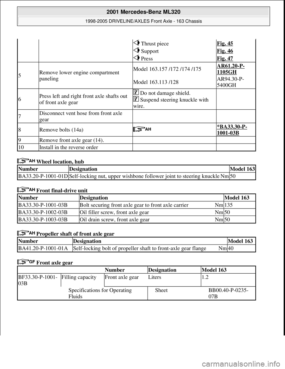
Wheel location, hub
Front final-drive unit
Propeller shaft of front axle gear
Front axle gear
Thrust pieceFig. 45
SupportFig. 46
PressFig. 47
5Remove lower engine compartment
panelingModel 163.157 /172 /174 /175AR61.20-P-
1105GH
Model 163.113 /128AR94.30-P-
5400GH
6Press left and right front axle shafts out
of front axle gear Do not damage shield.
Suspend steering knuckle with
wire.
7Disconnect vent hose from front axle
gear
8Remove bolts (14a) *BA33.30-P-
1001-03B
9Remove front axle gear (14).
10Install in the reverse order
NumberDesignationModel 163
BA33.20-P-1001-01DSelf-locking nut, upper wishbone follower joint to steering knuckleNm50
NumberDesignationModel 163
BA33.30-P-1001-03BBolt securing front axle gear to front axle carrierNm135
BA33.30-P-1002-03BOil filler screw, front axle gearNm50
BA33.30-P-1003-03BOil drain screw, front axle gearNm50
NumberDesignationModel 163
BA41.20-P-1001-01ASelf-locking bolt of propeller shaft to front-axle gear flangeNm40
Number Designation Model 163
BF33.30-P-1001-
03BFilling capacityFront axle gearLiters1.2
Specifications for Operating
FluidsSheetBB00.40-P-0235-
07B
2001 Mercedes-Benz ML320
1998-2005 DRIVELINE/AXLES Front Axle - 163 Chassis
me
Saturday, October 02, 2010 3:38:22 PMPage 43 © 2006 Mitchell Repair Information Company, LLC.
Page 2565 of 4133
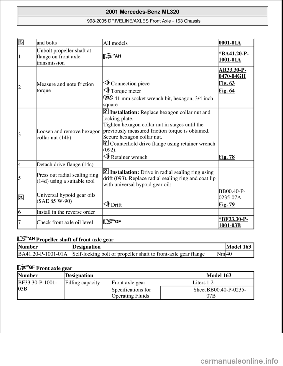
Propeller shaft of front axle gear
Front axle gear
and boltsAll models0001-01A
1
Unbolt propeller shaft at
flange on front axle
transmission
*BA41.20-P-
1001-01A
2Measure and note friction
torque
AR33.30-P-
0470-04GH
Connection pieceFig. 63
Torque meterFig. 64
41 mm socket wrench bit, hexagon, 3/4 inch
square
3Loosen and remove hexagon
collar nut (14b)
Installation: Replace hexagon collar nut and
locking plate.
Tighten hexagon collar nut in stages until the
previously measured friction torque is obtained.
Secure hexagon collar nut.
Counterhold drive flange using retainer wrench
(092).
Retainer wrenchFig. 78
4Detach drive flange (14c)
5Press out radial sealing ring
(14d) using a suitable tool Installation: Drive in radial sealing ring using
drift (093). Replace radial sealing ring and coat lip
with universal hypoid gear oil:
Universal hypoid gear oils
(SAE 85 W-90) BB00.40-P-
0235-07A
DriftFig. 79
6Install in the reverse order
7Check front axle oil level *BF33.30-P-
1001-03B
NumberDesignationModel 163
BA41.20-P-1001-01ASelf-locking bolt of propeller shaft to front-axle gear flangeNm40
NumberDesignationModel 163
BF33.30-P-1001-
03BFilling capacity Front axle gearLiters1.2
Specifications for
Operating FluidsSheetBB00.40-P-0235-
07B
2001 Mercedes-Benz ML320
1998-2005 DRIVELINE/AXLES Front Axle - 163 Chassis
me
Saturday, October 02, 2010 3:38:22 PMPage 46 © 2006 Mitchell Repair Information Company, LLC.
Page 2567 of 4133
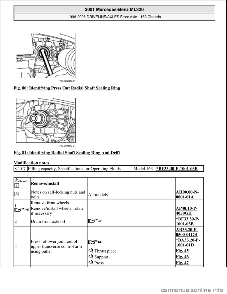
Fig. 80: Identifying Press Ou t Radial Shaft Sealing Ring
Fig. 81: Identifying Radial Sh aft Sealing Ring And Drift
Modification notes
8.1.07Filling capacity, Specificat ions for Operating FluidsModel 163*BF33.30-P-1001-03B
Remove/install
Notes on self-locking nuts and
boltsAll modelsAH00.00-N-
0001-01A
1
Remove front wheels
Remove/install wheels, rotate
if necessaryAP40.10-P-
4050GH
2Drain front axle oil *BF33.30-P-
1001-03B
3
Press follower joint out of
upper transverse control arm
using puller
AR33.20-P-
0500-01GH
*BA33.20-P-
1001-01D
Thrust pieceFig. 45
SupportFig. 46
PressFig. 47
2001 Mercedes-Benz ML320
1998-2005 DRIVELINE/AXLES Front Axle - 163 Chassis
me
Saturday, October 02, 2010 3:38:22 PMPage 48 © 2006 Mitchell Repair Information Company, LLC.
Page 2568 of 4133
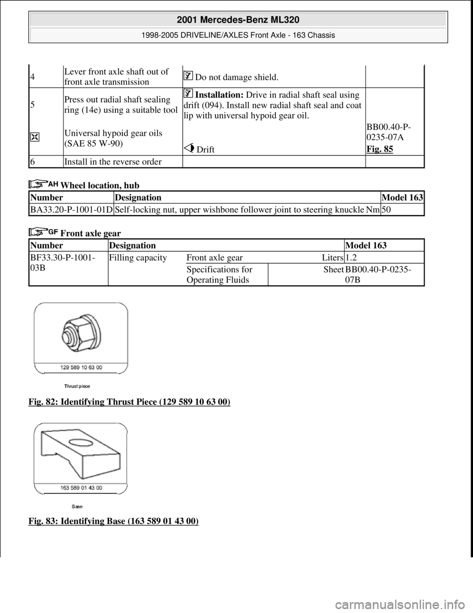
Wheel location, hub
Front axle gear
Fig. 82: Identifying Thrust Piece (129 589 10 63 00)
Fig. 83: Identifying Base (163 589 01 43 00)
4Lever front axle shaft out of
front axle transmission Do not damage shield.
5Press out radial shaft sealing
ring (14e) using a suitable tool Installation: Drive in radial shaft seal using
drift (094). Install new radial shaft seal and coat
lip with universal hypoid gear oil.
Universal hypoid gear oils
(SAE 85 W-90) BB00.40-P-
0235-07A
DriftFig. 85
6Install in the reverse order
NumberDesignationModel 163
BA33.20-P-1001-01DSelf-locking nut, upper wishbone foll ower joint to steering knuckleNm50
NumberDesignationModel 163
BF33.30-P-1001-
03BFilling capacityFront axle gearLiters1.2
Specifications for
Operating FluidsSheetBB00.40-P-0235-
07B
2001 Mercedes-Benz ML320
1998-2005 DRIVELINE/AXLES Front Axle - 163 Chassis
me
Saturday, October 02, 2010 3:38:22 PMPage 49 © 2006 Mitchell Repair Information Company, LLC.
Page 2597 of 4133

2
Remove covers at seat frame of 60% bench
seat
As of VIN A145273, X708319.
AR91.12-P-1100GH
Only remove the covers which are
identified in the document with A, D and E.
3
Fold 60% bench seat forward into footwell
As of VIN A145273, X708319. See
operator's manual.
4
Pull floor covering below rear seat mounting
bracket (1) of 60% seat forward
Ensure that the floor covering is not torn
when pulled forward.
As of VIN A145273, X708319.
5
Pull floor covering below front corner of trim
panel of C-pillar (2) forward
Ensure that the floor covering is not torn
when pulled forward.
As of VIN A145273, X708319.
6
Cut into floor covering directly behind seat
retaining cable (5)
Ensure that the wiring harness (4) is not
damaged when cutting into floor covering.
As of VIN A145273, X708319. broken line
marks cut-in.
7
Turn back floor covering to gain access to
cap (84)
Do not kink floor covering.
8
Remove cap (84)
Cap (84) is sealed in with body sealer.
Heat with hot air blower to make it easier to
remove.
Installation:
Replace cap and install with
new sealing compound.
9
Detach fuel feed line (90/12) and fuel return
line (90/11) and, if fitted, the fuel line at
connection (90/13)
Do not kink the fuel lines.
If no stationary heater is fitted to vehicle,
do not remove connection (90/13) otherwise
housing will be damaged.
*163589003700
10
Remove nut (89)
*163589010700
*BA47.20-P-1006-01B
11
Remove housing (3)
Fuel lever sensor and housing are a
single part and cannot be removed separately.
Installation:
Re-install nut (89) together
with seal (89/2).
Apply a thin film of oil to seal.
12
Install in the reverse order
Fuel pump
Number
Designation
Engine 612Engine 628
BA47.20-P-1006-01B
Union nut for fuel tank sensor on fuel
tank
Nm
6565
Fuel tank
Number
Designation
Models
163.113/
136/154/
172 up to
31.08.01
Model
163.113/
136/154/
172 as of
01.09.01
Model
163.157/
175
Model
163.128
BF47.10-P-1001-01A
Fuel tank capacity
Total capacity
Liter
728383
Reserve capacity
Liter
101212
Copyright DaimlerChrysler AG 28.05.2006 CD-Ausgabe G/10/04 . This WIS print-out will not be recorde
d by Modification services.
Page 2
Page 3212 of 4133
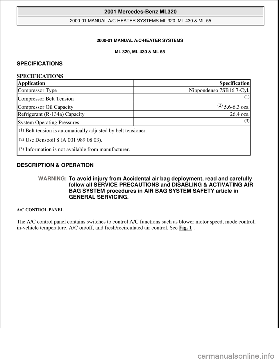
2000-01 MANUAL A/C-HEATER SYSTEMS
ML 320, ML 430 & ML 55
SPECIFICATIONS
SPECIFICATIONS
DESCRIPTION & OPERATION
A/C CONTROL PANEL
The A/C control panel contains switches to control A/C functions such as blower motor speed, mode control,
i
n-vehicle temperature, A/C on/off, and fresh/recirculated air control. See Fig. 1.
ApplicationSpecification
Compressor TypeNippondenso 7SB16 7-Cyl.
Compressor Belt Tension(1)
Compressor Oil Capacity(2) 5.6-6.3 ozs.
Refrigerant (R-134a) Capacity26.4 ozs.
System Operating Pressures(3)
(1)Belt tension is automatically adjusted by belt tensioner.
(2)Use Densooil 8 (A 001 989 08 03).
(3)Information is not available from manufacturer.
WARNING:To avoid injury from Accidental air bag deployment, read and carefully
follow all SERVICE PRECAUTIONS and DISABLING & ACTIVATING AIR
BAG SYSTEM procedures in AIR BAG SYSTEM SAFETY article in
GENERAL SERVICING.
2001 Mercedes-Benz ML320
2000-01 MANUAL A/C-HEATER SYSTEMS ML 320, ML 430 & ML 55
2001 Mercedes-Benz ML320
2000-01 MANUAL A/C-HEATER SYSTEMS ML 320, ML 430 & ML 55
me
Saturday, October 02, 2010 3:25:10 PMPage 1 © 2006 Mitchell Repair Information Company, LLC.
me
Saturday, October 02, 2010 3:25:13 PMPage 1 © 2006 Mitchell Repair Information Company, LLC.
Page 3445 of 4133

A/C compressor
A/C compressor
CORRECTING OIL LEVEL IN AIR CONDITIONING AFTER REPLACING PARTS - AR83.30-P-5252E
MODEL 163 with CODE (580) Air conditioning or Tempmatic for USA
A/C compressor 7SB16
MODEL 202 with CODE (580) Air conditioning or Tempmatic for USA with CODE (581a) Air
conditioning (Automatic) A/C compressor ND6CA17, A/C compressor 7SB16
MODEL 208 with CODE (580) Air conditioning or Tempmatic for USA with CODE (581a) Air
1If loss of refrigerant is <
400 g (no leakage
detectable) do not add
compressor oil ?
Carry out leak-tightness
test refer to SI83/85
2If loss of refrigerant is >
400 g (leakage detectable)
fill with new compressor
oil, also ? *BF83.55-P-1009-01A
Replace fluid reservoir
Models 202, 208, 210AR83.30-P-6520E
Model 163AR83.30-P-6520GH
Models 215, 220AR83.30-P-6520M
NumberDesignationA/C
compressor
7SB16 in
models 140,
170, 202, 208,
210A/C
compressor
ND6CA17 in
model 202A/C
compressor
7SB16
Refrigerant
R134a in
model 163
BF83.55-P-
1009-01AAdditional oil
capacity when
leakage
detectedCompressor oilcm3202020
Specifications
for service
productsSheetBB00.40-P-
0362-00ABB00.40-P-
0362-00ABB00.40-P-
0362-00A
NumberDesignationA/C compressor
7SE16 in model
215A/C compressor
7SE16 in model
220
BF83.55-P-
1009-01AAdditional oil
capacity when
leakage detectedCompressor oilcm32020
Specifications for
service productsSheetBB00.40-P-
0362-00ABB00.40-P-
0362-00A
2001 Mercedes-Benz ML320
1998-2005 HVAC Climate Control - 163 Chassis
me
Saturday, October 02, 2010 3:23:18 PMPage 201 © 2006 Mitchell Repair Information Company, LLC.
Page 3448 of 4133
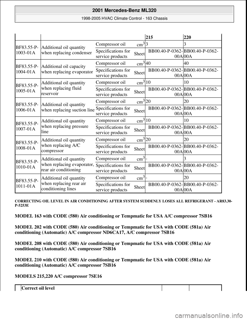
CORRECTING OIL LEVEL IN AIR CONDITIONING AFTER SYSTEM SUDDENLY LOSES ALL REFRIGERANT - AR83.30-
P-5253E
MODEL 163 with CODE (580) Air conditioning or Tempmatic for USA A/C compressor 7SB16
MODEL 202 with CODE (580) Air conditioning or Tempmatic for USA with CODE (581a) Air
conditioning (Automatic) A/C compressor ND6CA17, A/C compressor 7SB16
MODEL 208 with CODE (580) Air conditioning or Tempmatic for USA with CODE (581a) Air
conditioning (Automatic) A/C compressor 7SB16
MODEL 210 with CODE (580) Air conditioning or Tempmatic for USA with CODE (581a) Air
conditioning (Automatic) A/C compressor 7SB16
MODELS 215,220 A/C compressor 7SE16
215220
BF83.55-P-
1003-01AAdditional oil quantity
when replacing condenserCompressor oilcm333
Specifications for
service productsSheetBB00.40-P-0362-
00ABB00.40-P-0362-
00A
BF83.55-P-
1004-01AAdditional oil capacity
when replacing evaporatorCompressor oilcm34040
Specifications for
service productsSheetBB00.40-P-0362-
00ABB00.40-P-0362-
00A
BF83.55-P-
1005-01AAdditional oil quantity
when replacing fluid
reservoirCompressor oilcm31010
Specifications for
service productsSheetBB00.40-P-0362-
00ABB00.40-P-0362-
00A
BF83.55-P-
1006-01AAdditional oil quantity
when replacing suction lineCompressor oilcm32020
Specifications for
service productsSheetBB00.40-P-0362-
00ABB00.40-P-0362-
00A
BF83.55-P-
1007-01AAdditional oil quantity
when replacing pressure
lineCompressor oilcm31010
Specifications for
service productsSheetBB00.40-P-0362-
00ABB00.40-P-0362-
00A
BF83.55-P-
1008-01AAdditional oil quantity
when replacing A/C
compressorCompressor oilcm32020
Specifications for
service productsSheetBB00.40-P-0362-
00ABB00.40-P-0362-
00A
BF83.55-P-
1010-01AAdditional oil quantity
when replacing evaporator,
rear air conditioningCompressor oilcm3-3
Specifications for
service productsSheetBB00.40-P-0362-
00ABB00.40-P-0362-
00A
BF83.55-P-
1011-01AAdditional oil quantity
when replacing rear air
conditioning linesCompressor oilcm3-20
Specifications for
service productsSheetBB00.40-P-0362-
00ABB00.40-P-0362-
00A
Correct oil level
2001 Mercedes-Benz ML320
1998-2005 HVAC Climate Control - 163 Chassis
me
Saturday, October 02, 2010 3:23:18 PMPage 204 © 2006 Mitchell Repair Information Company, LLC.
Page 3449 of 4133
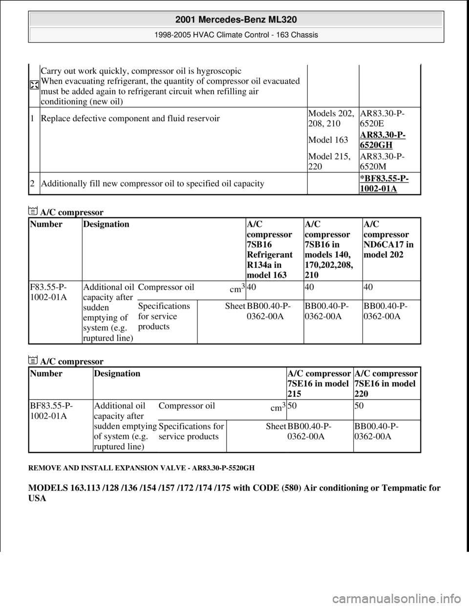
A/C compressor
A/C compressor
REMOVE AND INSTALL EXPANSION VALVE - AR83.30-P-5520GH
MODELS 163.113 /128 /136 /154 /157 /172 /174 /175 with CODE (580) Air conditioning or Tempmatic for
USA
Carry out work quickly, compressor oil is hygroscopic
When evacuating refrigerant, the quantity of compressor oil evacuated
must be added again to refrigerant circuit when refilling air
conditioning (new oil)
1Replace defective component and fluid reservoirModels 202,
208, 210AR83.30-P-
6520E
Model 163AR83.30-P-
6520GH
Model 215,
220AR83.30-P-
6520M
2Additionally fill new compressor oil to specified oil capacity *BF83.55-P-
1002-01A
NumberDesignationA/C
compressor
7SB16
Refrigerant
R134a in
model 163A/C
compressor
7SB16 in
models 140,
170,202,208,
210A/C
compressor
ND6CA17 in
model 202
F83.55-P-
1002-01AAdditional oil
capacity after
sudden
emptying of
system (e.g.
ruptured line)Compressor oilcm3404040
Specifications
for service
productsSheetBB00.40-P-
0362-00ABB00.40-P-
0362-00ABB00.40-P-
0362-00A
NumberDesignationA/C compressor
7SE16 in model
215A/C compressor
7SE16 in model
220
BF83.55-P-
1002-01AAdditional oil
capacity after
sudden emptying
of system (e.g.
ruptured line)Compressor oilcm35050
Specifications for
service productsSheetBB00.40-P-
0362-00ABB00.40-P-
0362-00A
2001 Mercedes-Benz ML320
1998-2005 HVAC Climate Control - 163 Chassis
me
Saturday, October 02, 2010 3:23:18 PMPage 205 © 2006 Mitchell Repair Information Company, LLC.
Page 3452 of 4133
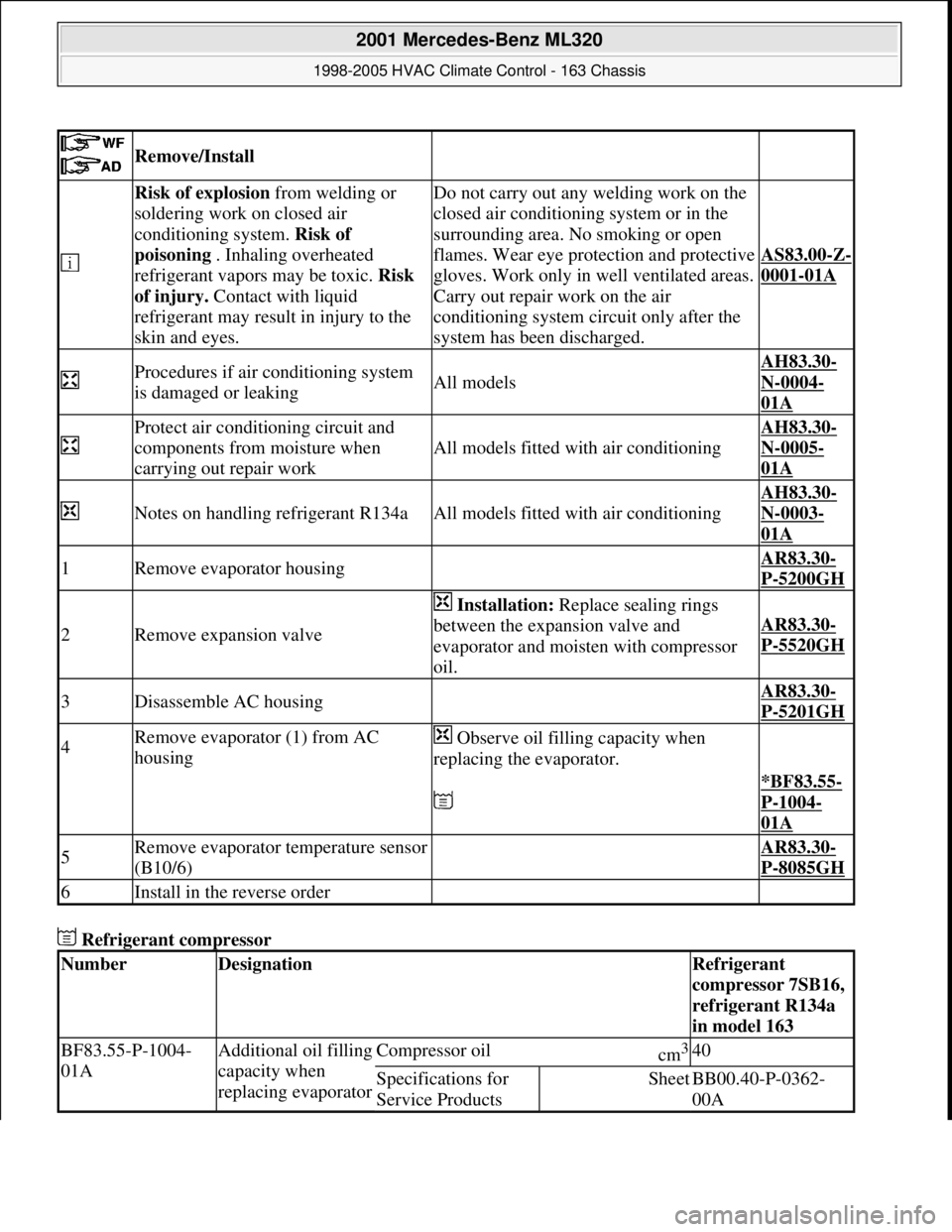
Refrigerant compressor
Remove/Install
Risk of explosion from welding or
soldering work on closed air
conditioning system. Risk of
poisoning . Inhaling overheated
refrigerant vapors may be toxic. Risk
of injury. Contact with liquid
refrigerant may result in injury to the
skin and eyes.Do not carry out any welding work on the
closed air conditioning system or in the
surrounding area. No smoking or open
flames. Wear eye protection and protective
gloves. Work only in well ventilated areas.
Carry out repair work on the air
conditioning system circuit only after the
system has been discharged.
AS83.00-Z-
0001-01A
Procedures if air conditioning system
is damaged or leakingAll models
AH83.30-
N-0004-
01A
Protect air conditioning circuit and
components from moisture when
carrying out repair work
All models fitted with air conditioning
AH83.30-
N-0005-
01A
Notes on handling refrigerant R134aAll models fitted with air conditioning
AH83.30-
N-0003-
01A
1Remove evaporator housing AR83.30-
P-5200GH
2Remove expansion valve
Installation: Replace sealing rings
between the expansion valve and
evaporator and moisten with compressor
oil.
AR83.30-
P-5520GH
3Disassemble AC housing AR83.30-
P-5201GH
4Remove evaporator (1) from AC
housing Observe oil filling capacity when
replacing the evaporator.
*BF83.55-
P-1004-
01A
5Remove evaporator temperature sensor
(B10/6) AR83.30-
P-8085GH
6Install in the reverse order
NumberDesignationRefrigerant
compressor 7SB16,
refrigerant R134a
in model 163
BF83.55-P-1004-
01AAdditional oil filling
capacity when
replacing evaporatorCompressor oilcm3 40
Specifications for
Service ProductsSheetBB00.40-P-0362-
00A
2001 Mercedes-Benz ML320
1998-2005 HVAC Climate Control - 163 Chassis
me
Saturday, October 02, 2010 3:23:18 PMPage 208 © 2006 Mitchell Repair Information Company, LLC.