coolant level MERCEDES-BENZ ML350 1997 Complete Service Manual
[x] Cancel search | Manufacturer: MERCEDES-BENZ, Model Year: 1997, Model line: ML350, Model: MERCEDES-BENZ ML350 1997Pages: 4133, PDF Size: 88.89 MB
Page 1132 of 4133

328 IndexK
Key
Global locking 89
Global unlocking 89
Loss of 90
Positions in steering lock 33
Remote control with folding key 88
Unlocking liftgate 89
Unlocking the driver’s door, fuel filler
flap 89
Key positions in steering lock 33
Key, Mechanical 261
Key, Remote control
Unlocking with 32
Kickdown 123, 313
L
Labels, identification 292
Lamp bulbs, exterior 266
Lamps, exterior
Front 266
Rear 267Lamps, indicator and warning
4-ETS 251, 252
ABS 242
Adjustable steering column 253
AIRBAG OFF 63, 243
BAS 78, 245, 246, 247
Battery indicator lamp 254
Brake pad wear 254
Brakes 244
CHECK ENGINE 248
Coolant 249
EBP 245
Engine diagnostics 248
ESP 245, 246, 247, 251
Front fog lamps 253
Fuel reserve 252
Low engine oil level 253
LOW RANGE 252
Low washer system fluid level 253
Seat belts 253
Service indicator 232
SRS 255
Turn signals 25LATCH child seat anchors 72
LATCH child seat mounts 72
Layout of poly-V-belt drive 293
Leather upholstery
Cleaning 239
Lever
For cruise control 150
License plate lamps
Replacing bulbs 267, 271
Liftgate
Closing 92
Opening 89, 91
Opening from inside 91
Opening from outside 91
Light alloy wheels
Cleaning 238
Lighter
Rear center console 169
Lighter see cigarette lighter 168
Page 2069 of 4133

Danger!
Risk of accident
caused by vehicle starting
off by itself when engine is running.
Risk of
injury
caused by contusions and burns when
working in engine during starting procedure
Secure vehicle to prevent it from moving.
Wear closed and snug-fitting work clothes.
Do not grasp hot or rotating parts.
AS00.00-Z-0005-01A
8
Pour in coolant
Warm up engine by running at moderate
revs. Top up coolant constantly at coolant
expansion reservoir. Close coolant expansion
tank once
coolant temperature is 60-70 °C.
*BF20.00-P-1001-02E
Note on coolant level
Model 124, 129, 140, 163.113, 168, 170, 202,
208, 210, 220, 463
AH20.00-P-1142-01A
9
Inspect cooling system for leaks
AR20.00-P-1010HA
Cooling system
Number
Designation
Engine
612.963
BF20.00-P-1001-02E
Cooling system
Total capacity
Liter
Y
11.0
Filling capacity of anticorrosion/
antifreeze agent down to
-37 °C
Liter
Y
5.5
Filling capacity of anticorrosion/
antifreeze up to -45 °C
Liter
Y
6.25
Specifications for Operating
Fluids
SheetBB00.40-P-0310-01A
SheetBB00.40-P-0325-00A
Copyright DaimlerChrysler AG 12.05.2006 CD-Ausgabe G/10/04 . This WIS print-out will not be recorde
d by Modification services.
Page 2
Page 2071 of 4133

1
Open cooling system cap (2) on coolant
expansion reservoir (1)
Cap with detent:
Turn cap carefully as far as the first detent,
release pressure, and then unscrew cap.
2-stage and 1-stage cap: Rotate cap half
a revolution in a counterclockwise direction,
release overpressure, then unscrew cap.
2.1Remove engine compartment paneling
Models 129, 202, 208, 210
AR61.20-P-1105AB
Models 163.172/ 174/ 175
AR61.20-P-1105GH
Models 163.113/ 128
AR94.30-P-5400GH
Model 211
AR61.20-P-1105T
Models 215, 220
AR61.20-P-1105M
Model 230
AR61.20-P-1105R
2.2Remove underride guard
Only on model 463
3.1
Remove air guide
Only on model 163 with engine 113.942
4
Drain coolant
Model 163: For draining coolant, detach
bottom coolant line at radiator or at coolant
pump.
Collect coolant Observe regulations for
disposal of coolant.
Installation:
On model 163 replace
radiator connection of hose clamps to coolant
hose, otherwise this can cause a damage to
the bolt/thread.
Hose clamp
*BA20.20-P-1004-01A
Pouring in
5
Pour in coolant
All except engine 137
*BF20.00-P-1001-02K
Engine 137
*BF20.00-P-1001-02M
Notes on coolant level
Engines 112, 113, 137, 275, 285
AH20.00-P-1142-01V
Notes on coolant level
Model 163 with engines 111, 112, 113
AH20.00-P-1142-01GH
6
Bleed cooling system
Let engine run, put heater on full heat
output.
Except stationary heater, code 228
AR20.00-P-1142-06GA
With stationary heater code 228
7
Inspect cooling system for leaks
AR20.00-P-1010HA
Radiator, coolant hoses
Number
Designation
Engines
112.942/
970,
113.942/
965/981
BA20.20-P-1004-01A
Hose clamp
Nm
3
Designation
Engines
112.910 /920
in model 202,
112.940
in model 208
Engines
112.911/921/941
in model 210
Engines
112.922/944/972
in model 220
BF20.00-P-1001-02K
Cooling system
Total capacity
Liters
Y
9.5
Y
10.0
Y
10.5
Capacity of
anticorrosion/antifreeze agent
down to -37°C
Liters
Y
4.75
Y
5.0
Y
5.0
Capacity of anticorrosion/
antifreeze agent down
to -45°C
Liters
Y
5.25
Y
5.5
Y
5.5
Specifications for Operating
Fluids
SheetBB00.40-P-0310-01ABB00.40-P-0310-01ABB00.40-P-0310-01A
SheetBB00.40-P-0325-00ABB00.40-P-0325-00ABB00.40-P-0325-00A
Copyright DaimlerChrysler AG 12.05.2006 CD-Ausgabe G/10/04 . This WIS print-out will not be recorde
d by Modification services.
Page 2
Page 2076 of 4133

Danger!
Risk of accident
caused by vehicle starting
off by itself when engine is running.
Risk of
injury
caused by contusions and burns when
working in engine during starting procedure
Secure vehicle to prevent it from moving.
Wear closed and snug-fitting work clothes.
Do not grasp hot or rotating parts.
AS00.00-Z-0005-01A
8
Pour in coolant
Warm up engine by running at moderate
revs. Top up coolant constantly at coolant
expansion reservoir. Close coolant expansion
tank once
coolant temperature is 60-70 °C.
*BF20.00-P-1001-02E
Note on coolant level
Model 124, 129, 140, 163.113, 168, 170, 202,
208, 210, 220, 463
AH20.00-P-1142-01A
9
Inspect cooling system for leaks
AR20.00-P-1010HA
Cooling system
Number
Designation
Engine
612.963
BF20.00-P-1001-02E
Cooling system
Total capacity
Liter
Y
11.0
Filling capacity of anticorrosion/
antifreeze agent down to
-37 °C
Liter
Y
5.5
Filling capacity of anticorrosion/
antifreeze up to -45 °C
Liter
Y
6.25
Specifications for Operating
Fluids
SheetBB00.40-P-0310-01A
SheetBB00.40-P-0325-00A
Copyright DaimlerChrysler AG 28.05.2006 CD-Ausgabe G/10/04 . This WIS print-out will not be recorde
d by Modification services.
Page 2
Page 2077 of 4133

GF54.30-P-4103GH
Coolant level switch, location/task/design/function
28.6.99
MODEL
163 as of 1.3.99
P54.30-2690-06
S41
Coolant level indicator electronic switch
The coolant level indicator electronic switch
(S41) is integrated in the coolant reservoir.
Coolant level switch, taskTo record the coolant level:
Coolant level
in order
or
below minimum
Coolant level switch, design
The coolant level indicator electronic switch
(S41) consists of two electrodes which are
permanently cast to the coolant reservoir and
a connector with contacts which have an
electrical connection to the electrodes.
Coolant level switch, function
The two electrodes are either immersed or
not immersed in the coolant depending on the
coolant level. As a result the test current
changes via the coolant level indicator
electronic switch (S41). This change is
evaluated by the instrument cluster (A1).
An alternating current is used so that the
electrodes do not disintegrate.
Copyright DaimlerChrysler AG 04.06.2006 CD-Ausgabe G/10/04 . This WIS print-out will not be recorde
d by Modification services.
Page 1
Page 2105 of 4133
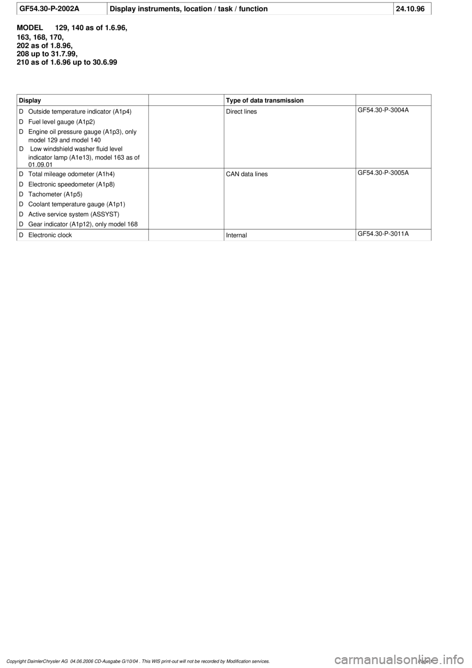
GF54.30-P-2002A
Display instruments, location / task / function
24.10.96
MODEL
129, 140 as of 1.6.96,
163, 168, 170,
202 as of 1.8.96,
208 up to 31.7.99,
210 as of 1.6.96 up to 30.6.99
Display
Type of data transmission
D
Outside temperature indicator (A1p4)
D
Fuel level gauge (A1p2)
D
Engine oil pressure gauge (A1p3), only
model 129 and model 140
D
Low windshield washer fluid level
indicator lamp (A1e13), model 163 as of
01.09.01
Direct lines
GF54.30-P-3004A
D
Total mileage odometer (A1h4)
D
Electronic speedometer (A1p8)
D
Tachometer (A1p5)
D
Coolant temperature gauge (A1p1)
D
Active service system (ASSYST)
D
Gear indicator (A1p12), only model 168
CAN data lines
GF54.30-P-3005A
D
Electronic clock
Internal
GF54.30-P-3011A
Copyright DaimlerChrysler AG 04.06.2006 CD-Ausgabe G/10/04 . This WIS print-out will not be recorde
d by Modification services.
Page 1
Page 2106 of 4133
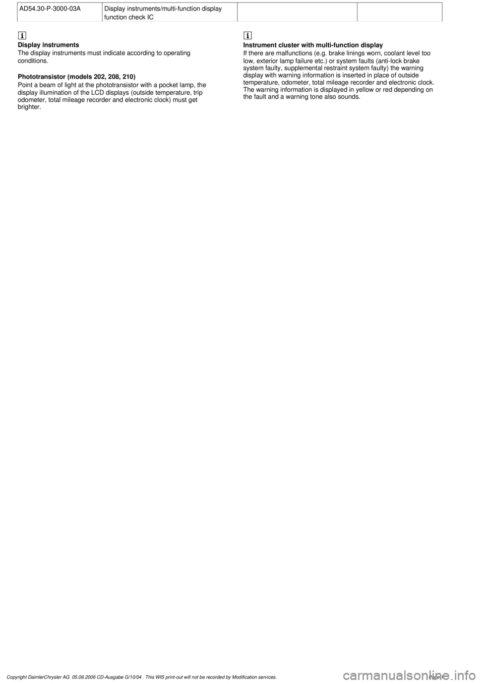
AD54.30-P-3000-03A
Display instruments/multi-function display
function check IC
Display
instruments
The display instruments must indicate according to operating
conditions.
Phototransistor (models 202, 208, 210)
Point a beam of light at the phototransistor with a pocket lamp, the
display illumination of the LCD displays (outside temperature, trip
odometer, total mileage recorder and electronic clock) must get
brighter.
Instrument cluster with multi-function display
If there are malfunctions (e.g. brake linings worn, coolant level too
low, exterior lamp failure etc.) or system faults (anti-lock brake
system faulty, supplemental restraint system faulty) the warning
display with warning information is inserted in place of outside
temperature, odometer, total mileage recorder and electronic clock.
The warning information is displayed in yellow or red depending on
the fault and a warning tone also sounds.
Copyright DaimlerChrysler AG 05.06.2006 CD-Ausgabe G/10/04 . This WIS print-out will not be recorde
d by Modification services.
Page 1
Page 2107 of 4133
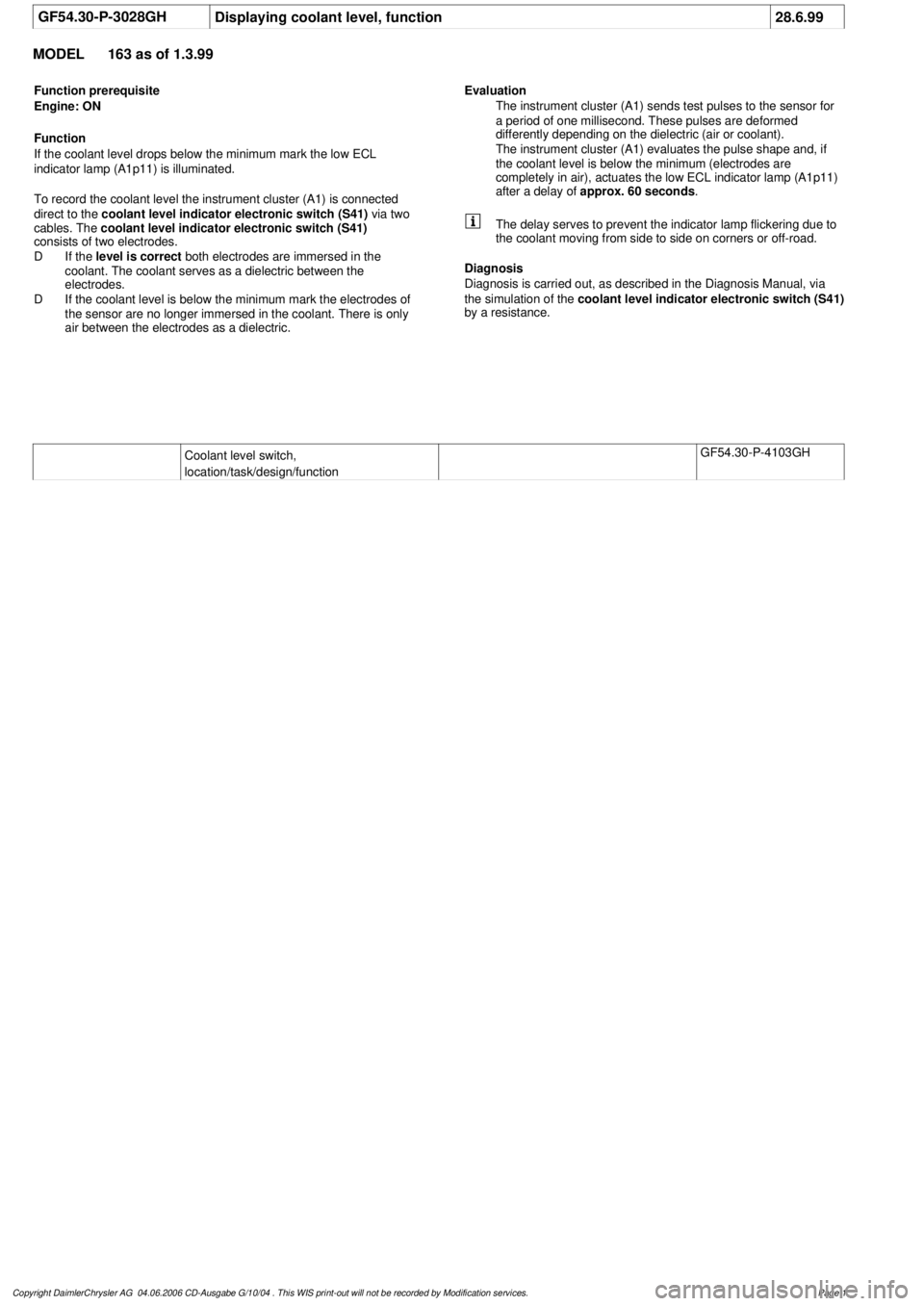
GF54.30-P-3028GH
Displaying coolant level, function
28.6.99
MODEL
163 as of 1.3.99
Function prerequisite
Engine: ON
Function
If the coolant level drops below the minimum mark the low ECL
indicator lamp (A1p11) is illuminated.
To record the coolant level the instrument cluster (A1) is connected
direct to the
coolant level indicator electronic switch (S41)
via two
cables. The
coolant level indicator electronic switch (S41)
consists of two electrodes.
D
If the
level is correct
both electrodes are immersed in the
coolant. The coolant serves as a dielectric between the
electrodes.
D
If the coolant level is below the minimum mark the electrodes of
the sensor are no longer immersed in the coolant. There is only
air between the electrodes as a dielectric. Evaluation
The instrument cluster (A1) sends test pulses to the sensor for
a period of one millisecond. These pulses are deformed
differently depending on the dielectric (air or coolant).
The instrument cluster (A1) evaluates the pulse shape and, if
the coolant level is below the minimum (electrodes are
completely in air), actuates the low ECL indicator lamp (A1p11)
after a delay of
approx. 60 seconds
.
The delay serves to prevent the indicator lamp flickering due to
the coolant moving from side to side on corners or off-road.
Diagnosis
Diagnosis is carried out, as described in the Diagnosis Manual, via
the simulation of the
coolant level indicator electronic switch (S41)
by a resistance.
Coolant level switch,
location/task/design/function
GF54.30-P-4103GH
Copyright DaimlerChrysler AG 04.06.2006 CD-Ausgabe G/10/04 . This WIS print-out will not be recorde
d by Modification services.
Page 1
Page 2173 of 4133
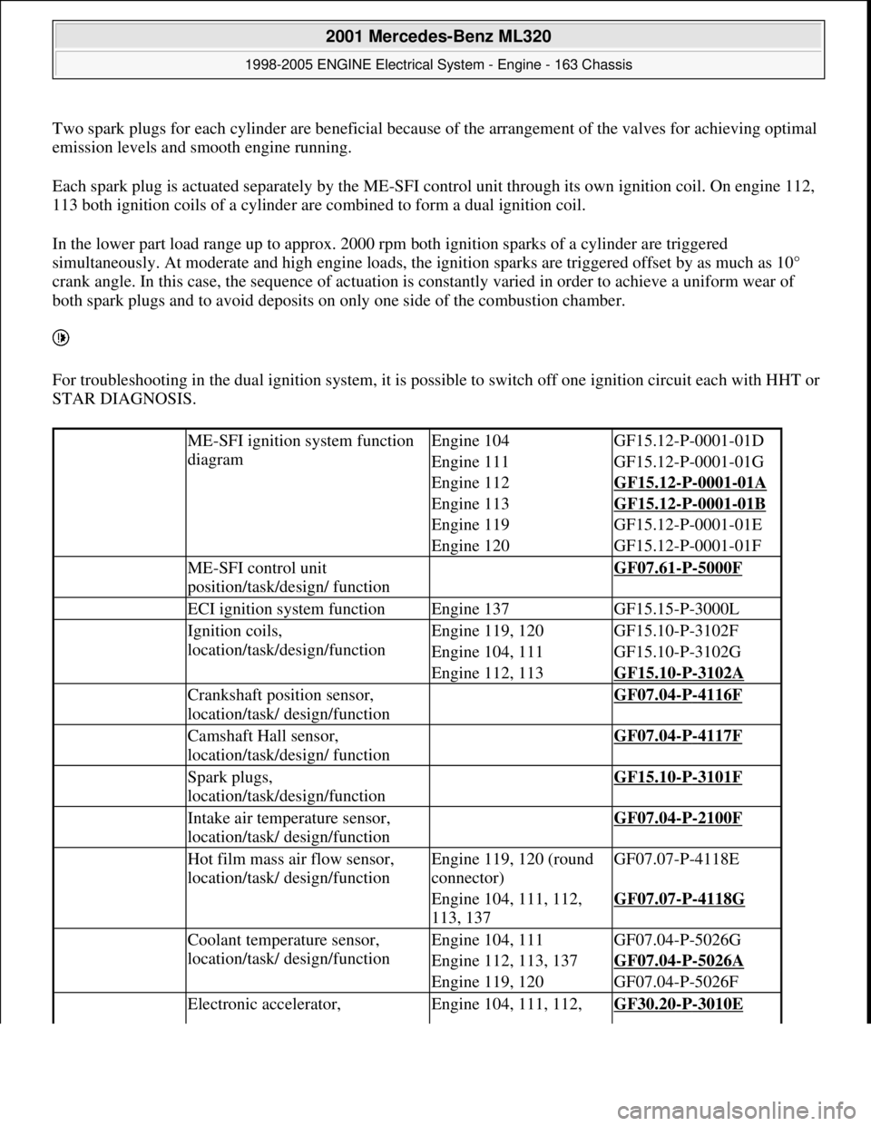
Two spark plugs for each cylinder are beneficial because of the arrangement of the valves for achieving optimal
emission levels and smooth engine running.
Each spark plug is actuated separately by the ME-SFI control unit through its own ignition coil. On engine 112,
113 both ignition coils of a cylinder are combined to form a dual ignition coil.
In the lower part load range up to approx. 2000 rpm both ignition sparks of a cylinder are triggered
simultaneously. At moderate and high engine loads, the ignition sparks are triggered offset by as much as 10°
crank angle. In this case, the sequence of actuation is constantly varied in order to achieve a uniform wear of
both spark plugs and to avoid deposits on only one side of the combustion chamber.
For troubleshooting in the dual ignition system, it is possible to switch off one ignition circuit each with HHT or
STAR DIAGNOSIS.
ME-SFI ignition system function
diagramEngine 104GF15.12-P-0001-01D
Engine 111GF15.12-P-0001-01G
Engine 112GF15.12-P-0001-01A
Engine 113GF15.12-P-0001-01B
Engine 119GF15.12-P-0001-01E
Engine 120GF15.12-P-0001-01F
ME-SFI control unit
position/task/design/ function GF07.61-P-5000F
ECI ignition system functionEngine 137GF15.15-P-3000L
Ignition coils,
location/task/design/functionEngine 119, 120GF15.10-P-3102F
Engine 104, 111GF15.10-P-3102G
Engine 112, 113GF15.10-P-3102A
Crankshaft position sensor,
location/task/ design/function GF07.04-P-4116F
Camshaft Hall sensor,
location/task/design/ function GF07.04-P-4117F
Spark plugs,
location/task/design/function GF15.10-P-3101F
Intake air temperature sensor,
location/task/ design/function GF07.04-P-2100F
Hot film mass air flow sensor,
location/task/ design/functionEngine 119, 120 (round
connector)GF07.07-P-4118E
Engine 104, 111, 112,
113, 137GF07.07-P-4118G
Coolant temperature sensor,
location/task/ design/functionEngine 104, 111GF07.04-P-5026G
Engine 112, 113, 137GF07.04-P-5026A
Engine 119, 120GF07.04-P-5026F
Electronic accelerator, Engine 104, 111, 112, GF30.20-P-3010E
2001 Mercedes-Benz ML320
1998-2005 ENGINE Electrical System - Engine - 163 Chassis
me
Saturday, October 02, 2010 3:18:54 PMPage 19 © 2006 Mitchell Repair Information Company, LLC.
Page 2459 of 4133

Engine 113 in model 129, 202, 208, 210
Engine 113 (except 113.965/981) in model 163
24.1Remove oil
reservoir on
power steering
pump (11)Model 163
Removal: Extract oil from rese rvoir. Remove circlip.
Installation: Replace sealing ring. Ch eck that circlip is
correctly seated.
Power steering -
checking and
correcting oil
level AP46.00-P-
4611BB
Hand pumpFig. 95
24.2Detach power
steering pump
(11) with oil
reservoir. Do not disconnect lines.
*BA46.30-P-
1005-01A
*BA46.30-P-
1010-01A
*BA46.30-P-
1010-01C
25.1Detach guide
pulley at timing
case coverModel 230.474
*BA13.25-P-
1008-01D
25.2Take off guide
pulley (15) at
coolant pump Except model 230.474
Take plastic cover off guide pulley.
*BA20.10-P-
1001-01C
*BA20.10-P-
1001-01M
26.1Remove
compressorEngine 112.960 in model 170.466
Engine 113.992 in model 230.474AR09.50-P-
4705SVK
27Remove air pump
(20)Engine 112 (except 112.960) in model 170
Engine 112 in 163, 202, 208, 210
Engines 113 in 163, 202, 208, 210AR14.30-P-
7251A
Engine 112.922 in model 220.063AR14.30-P-
7251AA
Engine 112.923 in model 129.059
Engine 112.943 in model 129.064
Engine 112.944 in model 220.065 /165
Engine 112.972 in model 220.067 /167
Engine 112.975 in model 220.087 /187
Engine 113.941 in models 220.070/170
Engine 113.948 in model 220.083 /183
Engine 113.960 in model 220.075/175
Engine 113.960 in model 215.375
Engine 113.961 in model 129.068
Engine 113.963 in models 230.475
Engine 113.966 in model 220.084 /184
2001 Mercedes-Benz ML320
1998-2005 ENGINE Complete engine - 163 Chassis
me
Saturday, October 02, 2010 3:17:57 PMPage 103 © 2006 Mitchell Repair Information Company, LLC.