flat tire MERCEDES-BENZ ML350 1997 Complete Workshop Manual
[x] Cancel search | Manufacturer: MERCEDES-BENZ, Model Year: 1997, Model line: ML350, Model: MERCEDES-BENZ ML350 1997Pages: 4133, PDF Size: 88.89 MB
Page 1677 of 4133
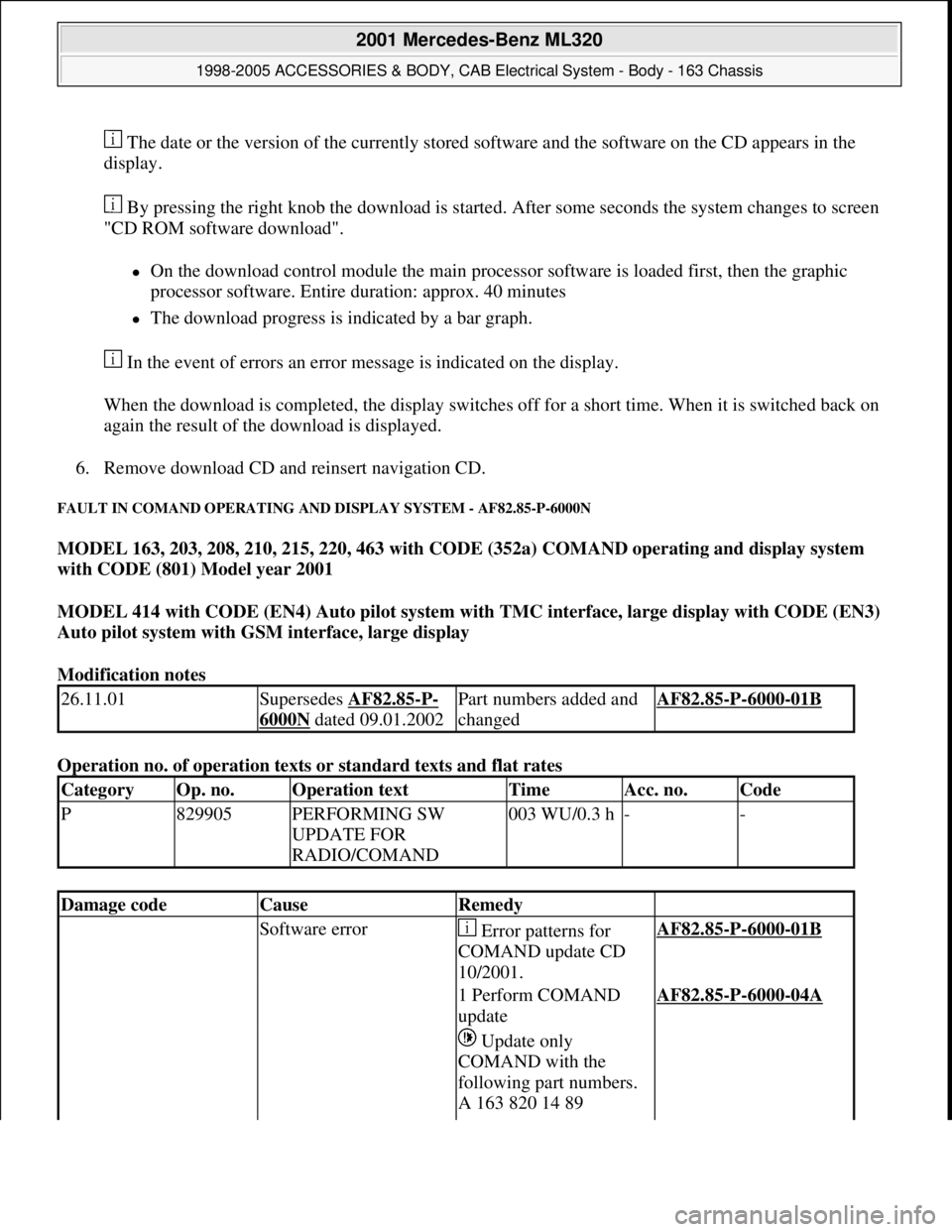
The date or the version of the currently stored software and the software on the CD appears in the
display.
By pressing the right knob the download is started. After some seconds the system changes to screen
"CD ROM software download".
On the download control module the main processor software is loaded first, then the graphic
processor software. Entire duration: approx. 40 minutes
The download progress is indicated by a bar graph.
In the event of errors an error message is indicated on the display.
When the download is completed, the display switches off for a short time. When it is switched back on
again the result of the download is displayed.
6. Remove download CD and reinsert navigation CD.
FAULT IN COMAND OPERATING AND DISPLAY SYSTEM - AF82.85-P-6000N
MODEL 163, 203, 208, 210, 215, 220, 463 with CODE (352a) COMAND operating and display system
with CODE (801) Model year 2001
MODEL 414 with CODE (EN4) Auto pilot system with TMC interface, large display with CODE (EN3)
Auto pilot system with GSM interface, large display
Modification notes
Operation no. of operation texts or standard texts and flat rates
26.11.01Supersedes AF82.85-P-
6000N dated 09.01.2002
Part numbers added and
changedAF82.85-P-6000-01B
CategoryOp. no.Operation textTimeAcc. no.Code
P829905PERFORMING SW
UPDATE FOR
RADIO/COMAND003 WU/0.3 h--
Damage codeCauseRemedy
Software error Error patterns for
COMAND update CD
10/2001.AF82.85-P-6000-01B
1 Perform COMAND
updateAF82.85-P-6000-04A
Update only
COMAND with the
following part numbers.
A 163 820 14 89
2001 Mercedes-Benz ML320
1998-2005 ACCESSORIES & BODY, CAB Electrical System - Body - 163 Chassis
me
Saturday, October 02, 2010 3:30:07 PMPage 182 © 2006 Mitchell Repair Information Company, LLC.
Page 3050 of 4133
SAFETY PRECAUTIONS FOR NEW VEHICLES THAT ARE BEING PUT IN STORAGE - AP00.70-P-1000ZZ
MODELS all
and rear axle
Frame
New vehicles in the
context of this description
are vehicles for which no
inspection has been carried
out to date. For other
vehicles, the instructions
in the Specifications for
Service Products apply
In areas in which
extremely high corrosive
attacks can be expected
from experience, the
measures given here are
not always sufficient even
for new vehiclesExport countries
In these cases, proceed in
accordance with
Specifications for Service
products.
Treatment of battery if
vehicle taken out of
service AR54.10-P-0006EA
Treatment of tire inflation
pressure if vehicle taken
out of serviceFor vehicles which will be
stored for longer than 2
months, the tire inflation
pressure should be
increased to approx. 4 bar
to prevent flattening of the
contact surface.
Treatment of break system
if vehicle taken out of
serviceWarm up service brake so
that adhering moisture at
the brake disks and the
brake pads evaporates.
This prevents the brake
pad from becoming stuck
to the brake disks.
Release parking brake.
The vehicle must be
secured by engaging a
gear/park pawl or by using
wedges.
Treatment of fuel system
if vehicle taken out of To protect the fuel tank
from corrosion, we
2004 Mercedes-Benz ML350
1998-2005 GENINFO Overall vehicle - 163 Chassis
me
Saturday, October 02, 2010 3:47:52 PMPage 405 © 2006 Mitchell Repair Information Company, LLC.
Page 3484 of 4133

AH40.10-P-9411-01A
Information on tires/rims
Model 124, 129, 140, 163, 168, 169,
170, 171, 199, 201, 202, 203, 208, 209,
210, 211, 215, 219, 220, 230, 240, 414,
450, 452,
639
Tires
D
For service conversions, the tire/disc wheel specifications and
dimensions should be compared with the entries in the
registration papers.
D
When mounting tires, the tires and rims must be carefully
matched in order to guarantee the concentricity of the wheel.
Identification of matching points on:
- Tires with a colored dot on the outside of the tire,
- Sheet steel disk wheel by a colored dot or punch mark on the
outside of the wheel,
- Perform this operation at the valve stem hole on light-alloy
disk wheels
With an additional paint spot or punch mark in the rim base
for the 140 Model Series.
D
Always replace the rubber valve.
-----------------------------------------------------------------------------------------
D
Damaged and defective tires must always be replaced. The
repair methods employed in the tire trade are not approved by
Mercedes-Benz. Small nicks (<0.8mm) on the tire's sidewall do
not usually pose a cause for concern, and continued use of
such tires is approved
D When replacing just one tire, install it on the front of the vehicle.
This does not apply to vehicles with different tires of varying
specifications on the front and rear wheels.
D
Only use tires listed in the valid Service Information bulletins
and repair instructions.
D
If the permissible maximum speed of an M+S tire is below the
maximum speed of the vehicle, an appropriate adhesive plate
must be attached in the driver's field of view.
-----------------------------------------------------------------------------------------
D
Tires permissible for higher speeds may be used.
D
Always fit all rims with tires of the same design, make and
version.
-----------------------------------------------------------------------------------------
D
Run in new tires for approx. 100 km at moderate speed.
D
Handed tires must be installed according to the arrow on the
side wall of the tire.
D
Tires are subject to an aging process with negative effects on
the properties of the tire. In order to ensure optimum
effectiveness in winter, M+S tires should not be used for longer
than 3 years.
-----------------------------------------------------------------------------------------
Tire pressure
(For specified values see tire pressure table in the fuel filler flap, on
the Vaneo BM 414 see B-pillar on the passenger side).
Too low tire pressure increases the rolling resistance and increases
the flexing energy of the tire. This causes the critical temperature limit
to be exceeded (carcass detachment) and destroys the tire. Respond
to loss of tire pressure by determining the source and replacing the
tire as indicated.
Cleaning
Using a spray wand with high-pressure nozzles to clean the wheel
can lead to tire damage. Such damage occurs especially on the tire
side walls. The following should be observed when using flat jet
nozzles:
D
Maintain a minimum distance of 300 mm
D
Do not direct the water jet at a single point on the surface of the
tire for any length of time.
-----------------------------------------------------------------------------------------
Mounting in bearings
Before putting into storage, clean tires thoroughly and check for
damage and adequate tread depth. Mark the position and running
direction of the tires with chalk. Do not store tires outdoors. Under the
influence of sunlight, heat, moving air and ozone the rubber looses
elasticity and strength, ages more quickly and becomes cracked.
Storage areas should be dry, cool and dark. Avoid drafts by keeping
doors and windows closed as much as possible. Do not bring tires
into contact with gasoline, oil or other greases as they dissolve the
rubber.
Disposal
Collection, storage and disposal should be performed in accordance
with the legal requirements and the company's own regulations.
-----------------------------------------------------------------------------------------
Copyright DaimlerChrysler AG 06.07.2006 CD-Ausgabe G/10/04 . This WIS print-out will not be recorde
d by Modification services.
Page 1
Page 3778 of 4133
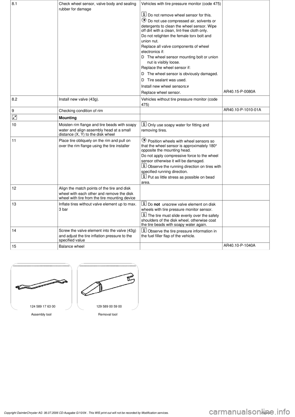
8.1
Check wheel sensor, valve body and sealing
rubber for damage
Vehicles with tire pressure monitor (code 475)
Do not remove wheel sensor for this.
Do not use compressed air, solvents or
detergents to clean the wheel sensor. Wipe
off dirt with a clean, lint-free cloth only.
Do not retighten the female torx bolt and
union nut.
Replace all valve components of wheel
electronics if:
D
The wheel sensor mounting bolt or union
nut is visibly loose.
Replace the wheel sensor if:
D
The wheel sensor is obviously damaged.
D
Tire sealant was used.
Install new wheel sensors:
#
Replace wheel sensor.
AR40.15-P-0080A
8.2
Install new valve (43g).
Vehicles without tire pressure monitor (code
475)
9
Checking condition of rim
AR40.10-P-1010-01A
Mounting
10
Moisten rim flange and tire beads with soapy
water and align assembly head at a small
distance (X, Y) to the disk wheel
Only use soapy water for fitting and
removing tires.
11
Place tire obliquely on the rim and pull on
over the rim flange using the tire installer
Position wheels with wheel sensors so
that the wheel sensor is approximately 180°
opposite the mounting head.
Do not apply compressive force to the wheel
sensor otherwise it will be damaged.
Observe the running direction on tires with
specified running direction.
Put as little stress as possible on bead
area.
12
Align the match points of the tire and disk
wheel with each other and remove the disk
wheel with tire from the tire mounting device
13
Inflate tires without valve element up to max.
3 bar
Do
not
unscrew valve element on disk
wheels with tire pressure monitor sensor.
The tire must slide evenly over the safety
shoulders of the disk wheel, otherwise coat
the tire beads with soapy water again.
14
Screw the valve element into the valve (43g)
and adjust the tire inflation pressure to the
specified value
Observe the tire pressure information in
the fuel filler flap of the vehicle.
15
Balance wheel
AR40.10-P-1040A
124 589 17 63 00 129 589 00 59 00
Removal tool
Assembly tool
Copyright DaimlerChrysler AG 06.07.2006 CD-Ausgabe G/10/04 . This WIS print-out will not be recorde
d by Modification services.
Page 2
Page 3948 of 4133
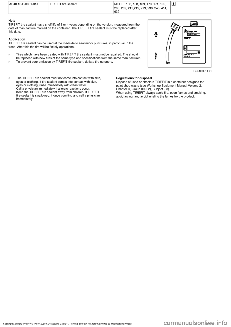
AH40.10-P-0001-01A
TIREFIT tire sealant
MODEL 163, 168, 169, 170, 171, 199,
203, 209, 211,215, 219, 230, 240, 414,
639
P40.10-0311-01
Note
TIREFIT tire sealant has a shelf life of 3 or 4 years depending on the version, measured from the
date of manufacture marked on the container. The TIREFIT tire sealant must be replaced after
this date.
Application
TIREFIT tire sealant can be used at the roadside to seal minor punctures, in particular in the
tread. After this the tire will be finitely operational.
F
Tires which have been treated with TIREFIT tire sealant must not be repaired. The should
be replaced with new tires of the same type and specifications from the same manufacturer.
F
To prevent odor emission by TIREFIT tire sealant, deflate tire outdoors.
F
The TIREFIT tire sealant must not come into contact with skin,
eyes or clothing. If tire sealant comes into contact with skin,
eyes or clothing, rinse immediately with clean water.
Call a physician immediately if allergic reactions occur.
Keep the TIREFIT tire sealant away from children. If TIREFIT
tire sealant is swallowed, induce vomiting and call a physician
immediately.
Regulations for disposal
Dispose of used or obsolete TIREFIT in a container designed for
paint shop waste (see Workshop Equipment Manual Volume 2,
Chapter U, Group 00 (22), Subject 2.3).
When using TIREFIT always avoid fire, open flames and smoking,
avoid arcing, and avoid inhaling the fumes fro the product.
Copyright DaimlerChrysler AG 06.07.2006 CD-Ausgabe G/10/04 . This WIS print-out will not be recorde
d by Modification services.
Page 1
Page 3993 of 4133
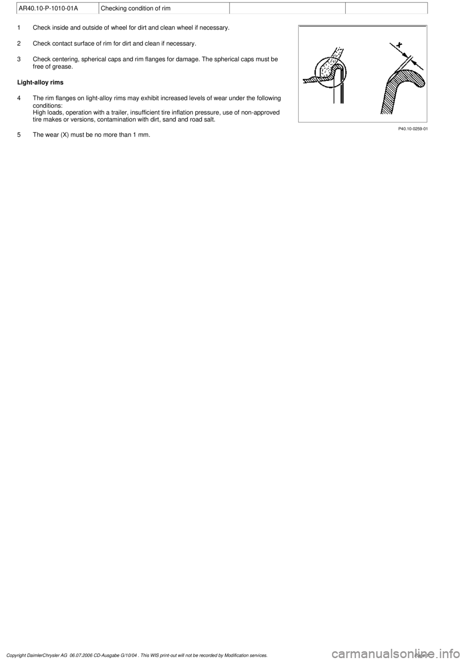
AR40.10-P-1010-01A
Checking condition of rim
P40.10-0259-01
1
Check inside and outside of wheel for dirt and clean wheel if necessary.
2
Check contact surface of rim for dirt and clean if necessary.
3
Check centering, spherical caps and rim flanges for damage. The spherical caps must be
free of grease.
Light-alloy rims
4
The rim flanges on light-alloy rims may exhibit increased levels of wear under the following
conditions:
High loads, operation with a trailer, insufficient tire inflation pressure, use of non-approved
tire makes or versions, contamination with dirt, sand and road salt.
5
The wear (X) must be no more than 1 mm.
Copyright DaimlerChrysler AG 06.07.2006 CD-Ausgabe G/10/04 . This WIS print-out will not be recorde
d by Modification services.
Page 1
Page 3994 of 4133
AP40.10-P-4050GH
Remove/install wheels, rotate if necessary
15.7.97
MODEL
163
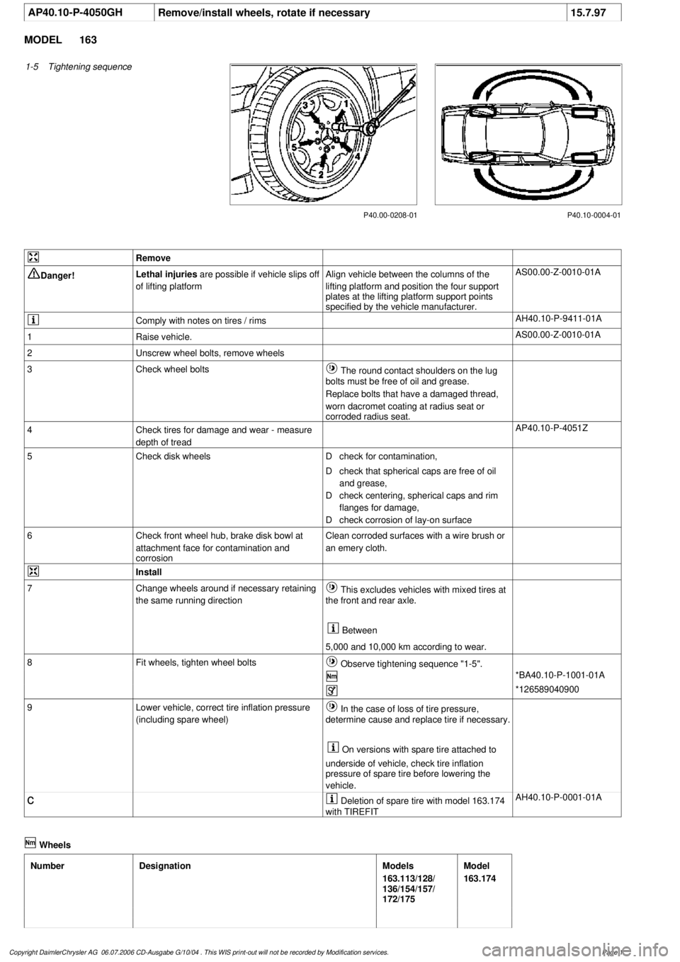
1-5
Tightening sequence
P40.10-0004-01
P40.00-0208-01
Remove
Danger!
Lethal injuries
are possible if vehicle slips off
of lifting platform
Align vehicle between the columns of the
lifting platform and position the four support
plates
at the lifting platform support points
specified by the vehicle manufacturer.
AS00.00-Z-0010-01A
Comply with notes on tires / rims
AH40.10-P-9411-01A
1
Raise vehicle.
AS00.00-Z-0010-01A
2
Unscrew wheel bolts, remove wheels
3
Check wheel bolts
The round contact shoulders on the lug
bolts must be free of oil and grease.
Replace bolts that have a damaged thread,
worn dacromet coating at radius seat or
corroded radius seat.
4
Check tires for damage and wear - measure
depth of tread
AP40.10-P-4051Z
5
Check disk wheels
D
check for contamination,
D
check that spherical caps are free of oil
and grease,
D
check centering, spherical caps and rim
flanges for damage,
D
check corrosion of lay-on surface
6
Check front wheel hub, brake disk bowl at
attachment face for contamination and
corrosion
Clean corroded surfaces with a wire brush or
an emery cloth.
Install
7
Change wheels around if necessary retaining
the same running direction
This excludes vehicles with mixed tires at
the front and rear axle.
Between
5,000 and 10,000 km according to wear.
8
Fit wheels, tighten wheel bolts
Observe tightening sequence "1-5".
*BA40.10-P-1001-01A
*126589040900
9
Lower vehicle, correct tire inflation pressure
(including spare wheel)
In the case of loss of tire pressure,
determine cause and replace tire if necessary.
On versions with spare tire attached to
underside of vehicle, check tire inflation
pressure of spare tire before lowering the
vehicle.
c
Deletion of spare tire with model 163.174
with TIREFIT
AH40.10-P-0001-01A
Wheels
Number
Designation
Models
163.113/128/
136/154/157/
172/175
Model
163.174
Copyright DaimlerChrysler AG 06.07.2006 CD-Ausgabe G/10/04 . This WIS print-out will not be recorde
d by Modification services.
Page 1