low beam MERCEDES-BENZ ML350 1997 Complete Workshop Manual
[x] Cancel search | Manufacturer: MERCEDES-BENZ, Model Year: 1997, Model line: ML350, Model: MERCEDES-BENZ ML350 1997Pages: 4133, PDF Size: 88.89 MB
Page 1660 of 4133
Consult a physician immediately.
Always consult a medical service or physician after administering first aid.
INJURY HAZARD FROM PINCHING AND CRUSHING, IN EXTREME CASES EXTREMITIES CAN EVEN BE CUT OFF
WHEN CAUGHT IN WINDSHIELD WIPER MECHANISM. - AS82.30-Z-0001-01A
Always remove ignition key before working on windshield wiper mechanism.
Injury hazard
When working in the area of the windshield wiper mechanism with the ignition key in position "1" or "2" the
wiper arm or wiper linkage can be pushed out of its end position and start running unintentionally . This can
result in severe injuries by cutting, pinching or crushing body parts.
Rules of behavior/protective measures
Always remove ignition key before working on windshield wiper mechanism.
Secure operating range of mechanism against reaching in.
Keep sufficient distance away from moving parts.
Supervise hazard area.
Wear tight fitting clothing and hair net.
TROUBLE DIAGNOSIS
HIGH BEAMS AND/OR LOW BEAMS DO NOT WORK - AF82.10-P-2009B
MODEL 129,140,163,170, 202, 208, 210, 215, 220 with CODE (612) Xenon headlamp unit
Modification notes
4.4.00Supersedes STIP 82.10-
019 from 24.03.2000
Damage codeCauseRemedy
Risk of death caused
by high voltage levels
present at xenon
headlamps.
Risk of explosion/risk
of fire caused by highly
inflammable substances
at damaged xenon bulbs
Risk of injury caused
by UV light, hot
components at xenon Do not come into contact with
parts that are under high voltage.
Persons with active electronic
implants (e.g. heart pacemakers)
must never work on xenon
headlamps. Switch off the
complete lighting system. Wear
insulated safety shoes, safety
glasses and protective gloves.
Remove highly inflammable
materials from the hazard area. AS82.10-Z-0001-01A
2001 Mercedes-Benz ML320
1998-2005 ACCESSORIES & BODY, CAB Electrical System - Body - 163 Chassis
me
Saturday, October 02, 2010 3:30:06 PMPage 165 © 2006 Mitchell Repair Information Company, LLC.
Page 1751 of 4133
MODELS 163.154 /172 /113 with CODE (612b) Xenon headlamp unit
MODELS 163.174/175/128/157
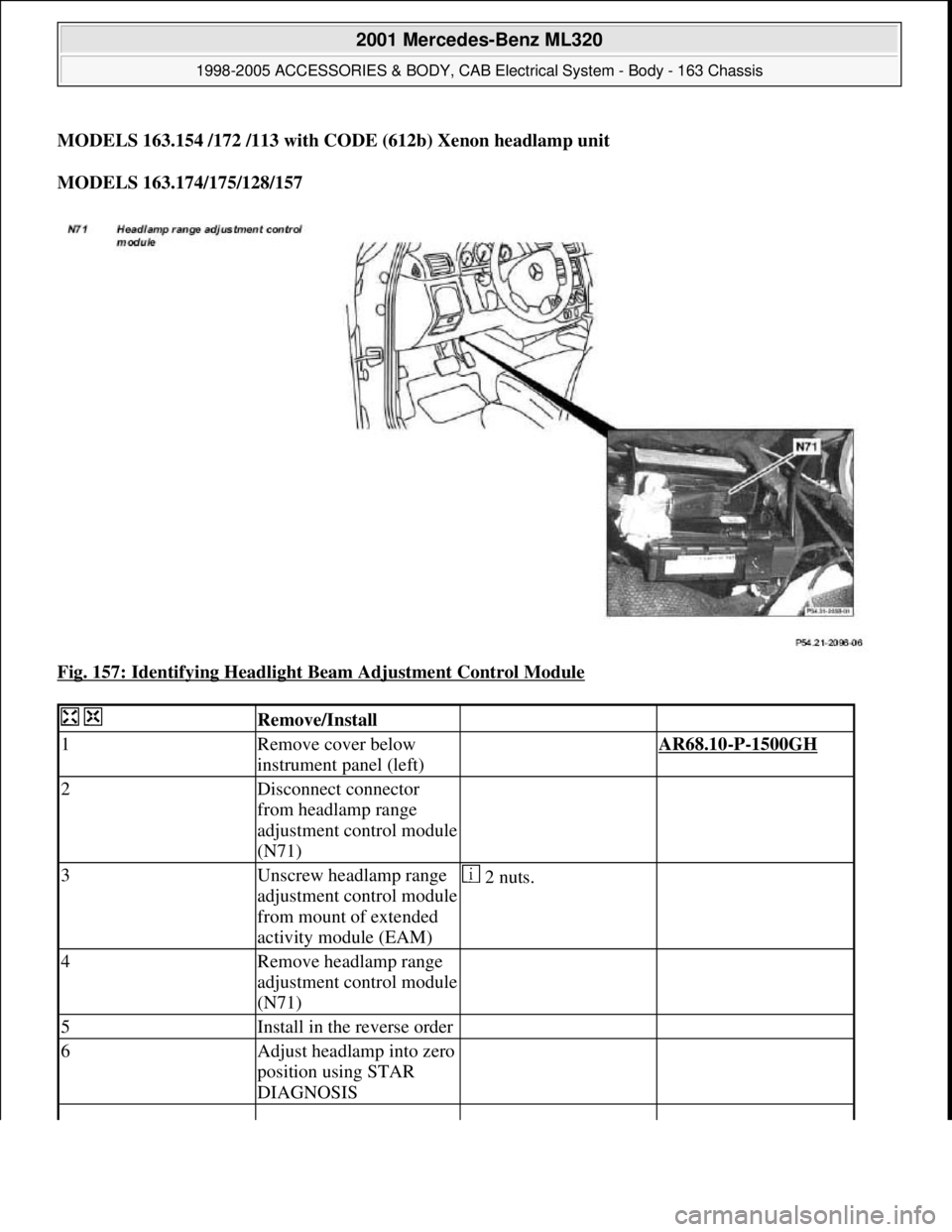
Fig. 157: Identifying Headlight Beam Adjustment Control Module
Remove/Install
1Remove cover below
instrument panel (left) AR68.10-P-1500GH
2Disconnect connector
from headlamp range
adjustment control module
(N71)
3Unscrew headlamp range
adjustment control module
from mount of extended
activity module (EAM) 2 nuts.
4Remove headlamp range
adjustment control module
(N71)
5Install in the reverse order
6Adjust headlamp into zero
position using STAR
DIAGNOSIS
2001 Mercedes-Benz ML320
1998-2005 ACCESSORIES & BODY, CAB Electrical System - Body - 163 Chassis
me
Saturday, October 02, 2010 3:30:08 PMPage 256 © 2006 Mitchell Repair Information Company, LLC.
Page 1819 of 4133
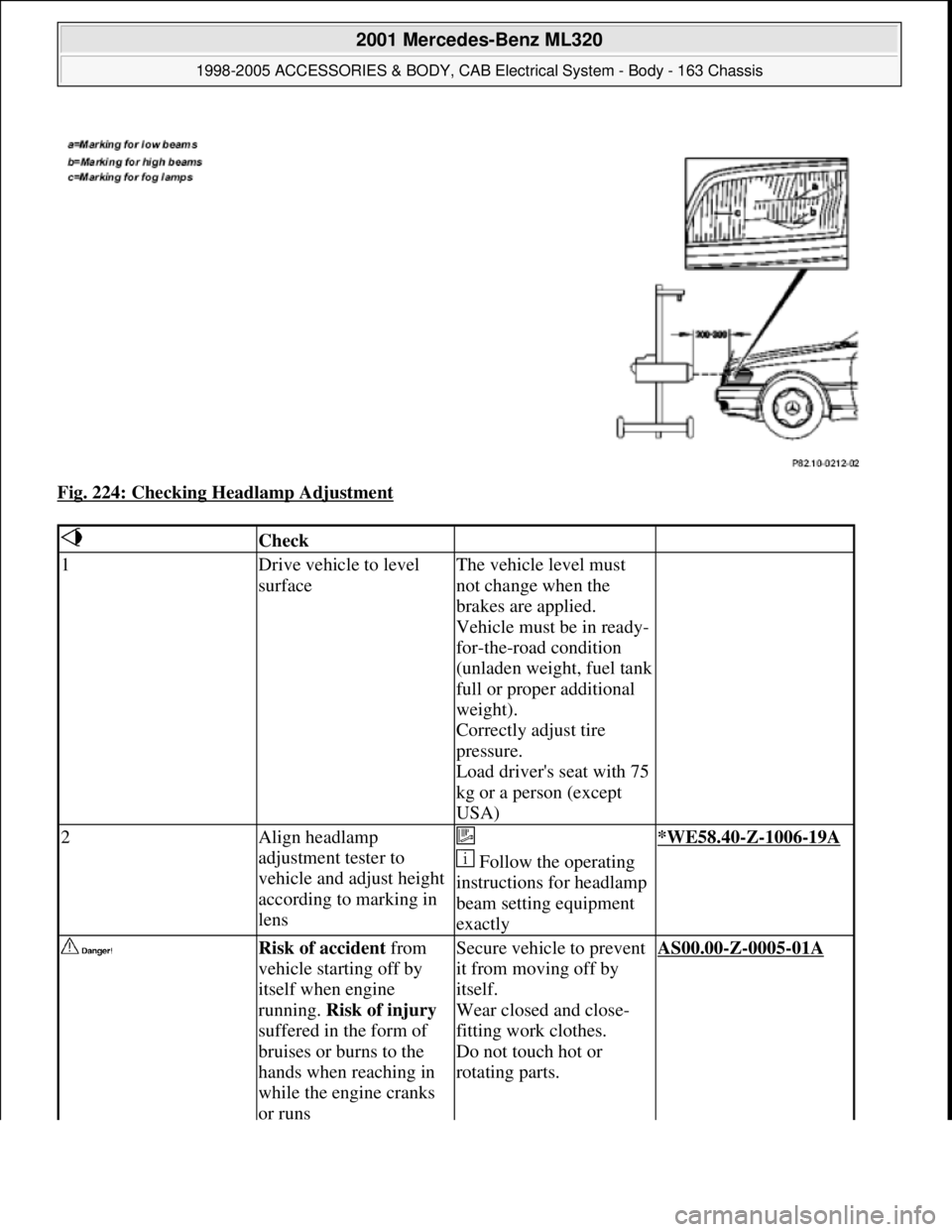
Fig. 224: Checking Headlamp Adjustment
Check
1Drive vehicle to level
surfaceThe vehicle level must
not change when the
brakes are applied.
Vehicle must be in ready-
for-the-road condition
(unladen weight, fuel tank
full or proper additional
weight).
Correctly adjust tire
pressure.
Load driver's seat with 75
kg or a person (except
USA)
2Align headlamp
adjustment tester to
vehicle and adjust height
according to marking in
lens
Follow the operating
instructions for headlamp
beam setting equipment
exactly*WE58.40-Z-1006-19A
Risk of accident from
vehicle starting off by
itself when engine
running. Risk of injury
suffered in the form of
bruises or burns to the
hands when reaching in
while the engine cranks
or runsSecure vehicle to prevent
it from moving off by
itself.
Wear closed and close-
fitting work clothes.
Do not touch hot or
rotating parts.AS00.00-Z-0005-01A
2001 Mercedes-Benz ML320
1998-2005 ACCESSORIES & BODY, CAB Electrical System - Body - 163 Chassis
me
Saturday, October 02, 2010 3:30:10 PMPage 324 © 2006 Mitchell Repair Information Company, LLC.
Page 1820 of 4133
Workshop equipment
WINDSHIELD WASHER - CHECKING AND CORRECTING FLUID LEVEL - AP82.35-P-8210GH
MODEL 163
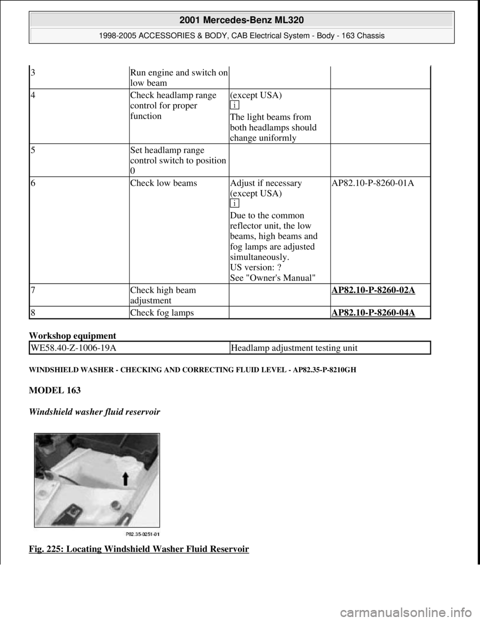
Windshield washer fluid reservoir
Fig. 225: Locating Windshield Washer Fluid Reservoir
3Run engine and switch on
low beam
4Check headlamp range
control for proper
function(except USA)
The light beams from
both headlamps should
change uniformly
5Set headlamp range
control switch to position
0
6Check low beamsAdjust if necessary
(except USA)
Due to the common
reflector unit, the low
beams, high beams and
fog lamps are adjusted
simultaneously.
US version: ?
See "Owner's Manual"AP82.10-P-8260-01A
7Check high beam
adjustment AP82.10-P-8260-02A
8Check fog lamps AP82.10-P-8260-04A
WE58.40-Z-1006-19AHeadlamp adjustment testing unit
2001 Mercedes-Benz ML320
1998-2005 ACCESSORIES & BODY, CAB Electrical System - Body - 163 Chassis
me
Saturday, October 02, 2010 3:30:10 PMPage 325 © 2006 Mitchell Repair Information Company, LLC.
Page 1970 of 4133
AP82.10-P-8260GH
Check and correct headlamp adjustment
2.7.97
MODEL
163
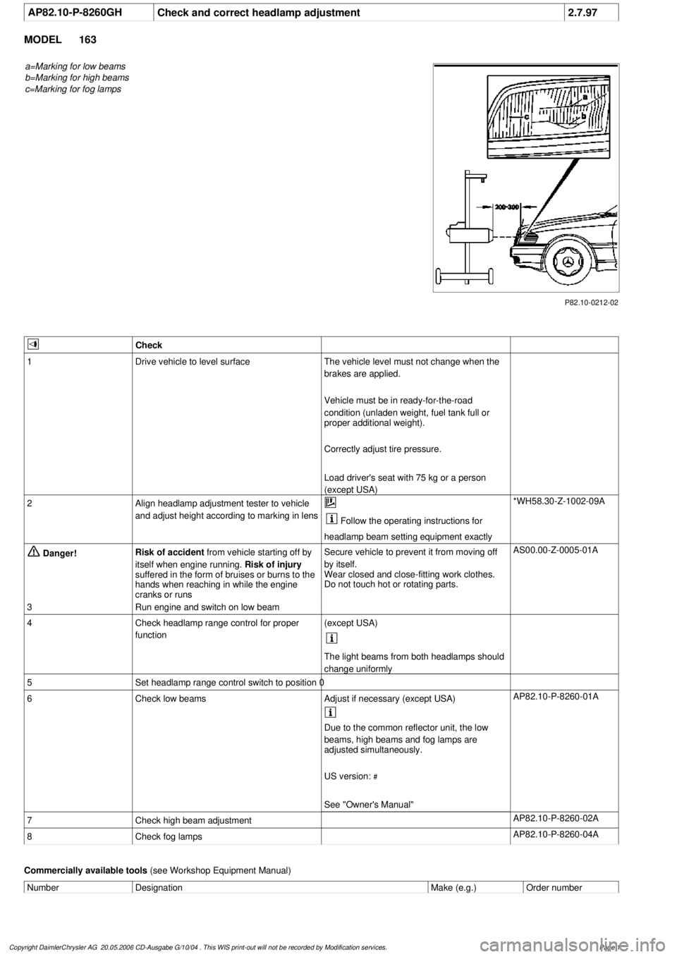
a=Marking for low beams
b=Marking for high beams
c=Marking for fog lamps
P82.10-0212-02
Check
1
Drive vehicle to level surface
The vehicle level must not change when the
brakes are applied.
Vehicle must be in ready-for-the-road
condition (unladen weight, fuel tank full or
proper additional weight).
Correctly adjust tire pressure.
Load driver's seat with 75 kg or a person
(except USA)
2
Align headlamp adjustment tester to vehicle
and adjust height according to marking in lens
Follow the operating instructions for
headlamp beam setting equipment exactly
*WH58.30-Z-1002-09A
Danger!
Risk of accident
from vehicle starting off by
itself when engine running.
Risk of injury
suffered in the form of bruises or burns to the
hands when reaching in while the engine
cranks or runs
Secure vehicle to prevent it from moving off
by itself.
Wear closed and close-fitting work clothes.
Do not touch hot or rotating parts.
AS00.00-Z-0005-01A
3
Run engine and switch on low beam
4
Check headlamp range control for proper
function
(except USA)
The light beams from both headlamps should
change uniformly
5
Set headlamp range control switch to position 0
6
Check low beams
Adjust if necessary (except USA)
AP82.10-P-8260-01A
Due to the common reflector unit, the low
beams, high beams and fog lamps are
adjusted simultaneously.
US version:
#
See "Owner's Manual"
7
Check high beam adjustment
AP82.10-P-8260-02A
8
Check fog lamps
AP82.10-P-8260-04A
Commercially available tools
(see Workshop Equipment Manual)
Number
Designation
Make (e.g.)
Order number
Copyright DaimlerChrysler AG 20.05.2006 CD-Ausgabe G/10/04 . This WIS print-out will not be recorde
d by Modification services.
Page 1
Page 2052 of 4133

Connect DC clip-on probe from engine tester with oscilloscope to positive battery terminal. See Fig. 11. Start
engine. Switch on low beam. Access diode test at 3000 RPM. See Fig. 12
-Fig. 14 . Replace generator as
necessar
y.
2001 Mercedes-Benz ML320
2001-04 STARTING & CHARGING SYSTEMS Generators & Regulators - 163 Chassis
me
Saturday, October 02, 2010 3:20:32 PMPage 18 © 2006 Mitchell Repair Information Company, LLC.
Page 2106 of 4133

AD54.30-P-3000-03A
Display instruments/multi-function display
function check IC
Display
instruments
The display instruments must indicate according to operating
conditions.
Phototransistor (models 202, 208, 210)
Point a beam of light at the phototransistor with a pocket lamp, the
display illumination of the LCD displays (outside temperature, trip
odometer, total mileage recorder and electronic clock) must get
brighter.
Instrument cluster with multi-function display
If there are malfunctions (e.g. brake linings worn, coolant level too
low, exterior lamp failure etc.) or system faults (anti-lock brake
system faulty, supplemental restraint system faulty) the warning
display with warning information is inserted in place of outside
temperature, odometer, total mileage recorder and electronic clock.
The warning information is displayed in yellow or red depending on
the fault and a warning tone also sounds.
Copyright DaimlerChrysler AG 05.06.2006 CD-Ausgabe G/10/04 . This WIS print-out will not be recorde
d by Modification services.
Page 1
Page 2142 of 4133
CIRCUIT PROTECTION DEVICES
CIRCUIT PROTECTION DEVICES LOCATION
box.
Fuel Pump RelayIn left side of engine compartment, in fuse & relay
box.
Headlamp Cleaning System RelayIn right front footwell fuse & relay box.
Heated Rear Window RelayIn right front footwell fuse & relay box.
Heater RelayAt right kick panel.
Heater Relay (Stage 1)At right kick panel.
Heater Relay (Stage 2)At right kick panel.
High Pressure/Return Pump RelayIn left side of engine compartment, in fuse & relay
box.
Left Front Power Window RelayIn left side of engine compartment, in fuse & relay
box.
Left Turn Signal RelayIn left side of engine compartment, in fuse & relay
box.
Low Beam Headlamp Relay (W/ DRL)In left side of engine compartment, in fuse & relay
box.
Rear Foglight RelayIn left side of engine compartment, in fuse & relay
box.
Rear Wall Door Washer Pump RelayIn left side of engine compartment, in fuse & relay
box.
Rear Window Defroster RelayIn right front footwell fuse & relay box.
Right Front Power Window RelayIn left side of engine compartment, in fuse & relay
box.
Right Turn Signal RelayIn left side of engine compartment, in fuse & relay
box.
Seat Comfort RelayIn right front footwell fuse & relay box.
Seat Heater Relay (Stage 1)On underside of left/right front seat.
Seat Heater Relay (Stage 2)On underside of left/right front seat.
Secondary Air Injection Pump RelayIn left side of engine compartment, in fuse & relay
box.
Starter RelayIn left side of engine compartment, in fuse & relay
box.
Two-Tone Horn RelayIn left side of engine compartment, in fuse & relay
box.
ComponentComponent Location
E-BoxIn left side of engine compartment.
Fuse & Relay BoxIn left side of engine compartment, in E-box. See
Fig. 1
.
Right Front Footwell Fuse & Relay BoxBelow right side of dash, behind kick panel. See
2001 Mercedes-Benz ML320
2001 MERCEDES-BENZ ML320 & ML430
me
Saturday, October 02, 2010 3:21:17 PMPage 2 © 2006 Mitchell Repair Information Company, LLC.
Page 2146 of 4133
MISCELLANEOUS
MISCELLANEOUS LOCATION
CONNECTORS
CONNECTORS LOCATION
Parking Brake SwitchOn parking brake support bracket.
Passenger's Seat Belt SwitchIn passenger's seat belt buckle.
Release Switch (BAS)Integral to brake booster.
Right Front Seat Belt Buckle SwitchIn passenger's seat belt buckle.
Rotary Tumbler Trunk Lid MicroswitchPart of tailgate latch assembly.
Stoplight SwitchOn brake pedal support.
ComponentComponent Location
Alarm HornIn left rear corner of engine compartment.
Alarm Siren W/ Auxiliary BatteryIn left rear corner of engine compartment.
Antenna Coil (Left)At left side of rear window, behind trim.
Antenna Coil (Right)At right side of rear window, behind trim.
Antenna SplitterOn right side of liftgate.
Audio AmplifierBehind left side of dash.
Blower Motor Preresistor GroupUnder right side of dash, in blower assembly.
Data Link Connector (DLC)Below left side of dash.
Diagnostic Module (OBD II) Scan Tool ConnectorBelow left side of dash.
Driver's ETR SquibOn base of left "B" pillar, behind trim.
FM/AM AmplifierIn liftgate, behind trim.
Front Passenger ETR SquibOn base of right "B" pillar, behind trim.
Garage Door TransmitterOn front center of roof.
Hands-Free MicrophoneOn front center of roof.
Low Beam Headlight Relay Shorting ClipIn left side of engine compartment, in fuse & relay
box.
Recirculated Air Flap ElementBehind right side of dash.
Transponder CoilTop right side of steering column, on ignition
switch.
ComponentComponent Location
X2/4 (Black, 2-Pin)Behind radio.
X11/4 (Black, 16-Pin)Below left side of dash.
X18 (Red, 28-Pin)Behind center of dash.
X18/1 (Black, 9-Pin)Under tailgate trim.
X18/A_B (Black, 16-Pin)At right kick panel.
X18/2 (1) (White, 10-Pin)At left rear of engine compartment.
X18/2 (2) (4-Pin)At left rear of engine compartment, in E-box.
2001 Mercedes-Benz ML320
2001 MERCEDES-BENZ ML320 & ML430
me
Saturday, October 02, 2010 3:21:17 PMPage 6 © 2006 Mitchell Repair Information Company, LLC.
Page 2224 of 4133
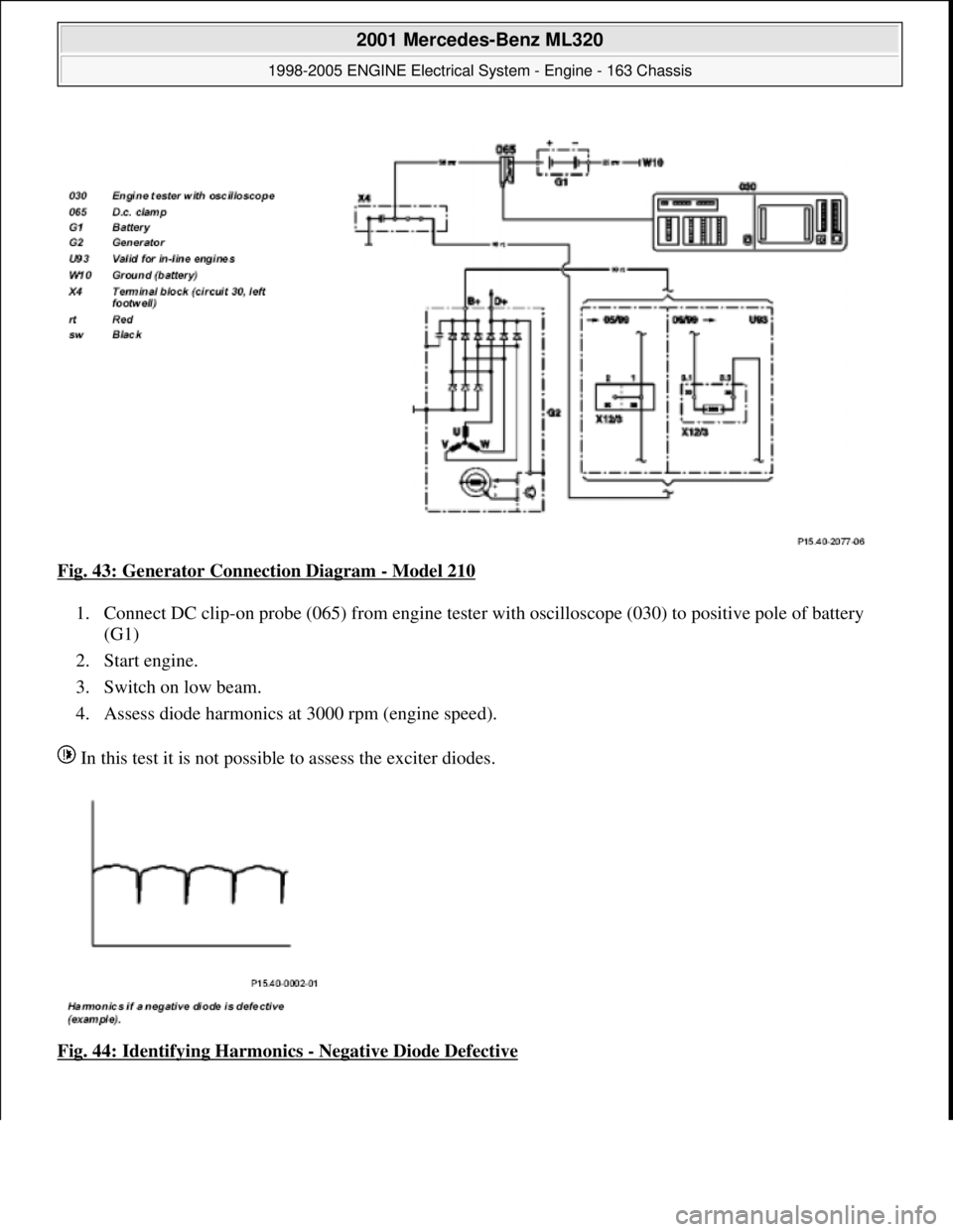
Fig. 43: Generator Connection Diagram - Model 210
1. Connect DC clip-on probe (065) from engine tester with oscilloscope (030) to positive pole of battery
(G1)
2. Start engine.
3. Switch on low beam.
4. Assess diode harmonics at 3000 rpm (engine speed).
In this test it is not possible to assess the exciter diodes.
Fig. 44: Identifying Harmonics
- Negative Diode Defective
2001 Mercedes-Benz ML320
1998-2005 ENGINE Electrical System - Engine - 163 Chassis
me
Saturday, October 02, 2010 3:18:55 PMPage 70 © 2006 Mitchell Repair Information Company, LLC.