oil temperature MERCEDES-BENZ ML350 1997 Complete Manual PDF
[x] Cancel search | Manufacturer: MERCEDES-BENZ, Model Year: 1997, Model line: ML350, Model: MERCEDES-BENZ ML350 1997Pages: 4133, PDF Size: 88.89 MB
Page 2237 of 4133

Oil replenishments are always only detected once the following
conditions are met:
D
the replenished quantity is
at least 1 l
D
after replenishing the oil, the car must be driven a distance of
at
least 5 km
under
normal driving conditions
at an
oil
temperature of at least 60 °C
.
There are instances, however, in which the readout of the remaining
distance nevertheless appears implausible after replenishing oil;
according to the display, no bonus or only a small bonus has been
issued. This is caused by the fact that the remaining distance is
always only displayed within a range from 15 000 km up to 30 000
km (or 20 000 km up to 40 000 km in the case of engine 668), but
internally the system calculates with the actual values which may also
be beyond this range. These internal values can only be displayed
with the HHT.
In the charts overleaf, a number of examples of this are presented.
The horizontal (x) axis represents the service interval and the vertical
(y) axis is the remaining distance in each case in km.
The readout of ASSYST in the instrument cluster always moves
within the light range.
The remaining distance calculated internally may also, however, be
within the two dark ranges. These internal values can only be
displayed with the HHT.
All examples relate to gasoline engines fitted with an oil sensor.
P00.20-0201-06
Example 1 :
Sufficient oil was added during the oil change.
This means that the starting distance is 15
000 km.
After 10 000 km oil is topped up under normal
driving conditions (a). The bonus (B1) is
issued and displayed. What this means is that
when the remaining distance is retrieved, a
greater remaining distance is displayed.
(Provided the aforementioned conditions for
detecting the oil replenishment are met.)
Oil is topped up again after a further
5 000 km (b). In this case also a bonus (B2) is
issued and displayed.
If, after this, no further oil is topped up and
the car continues to be driven in the same
manner, a service interval of about
24 000 km is thus achieved.
In this example, the curve moves at all points
within the light range of the chart;
consequently, all the oil replenishments are
displayed by increasing the remaining
distance.
P00.20-0204-06
Example 2:
The specified quantity of oil was added when
the oil was changed.
The car is driven under very favorable
conditions and oil is topped up after
10 000 km (a). Internally, the bonus B1 is
issued, the service interval is extended
accordingly by enlarging the remaining
distance. However, as the curve is sometimes
within the shaded area, only the part of B1
which is within the light area, is at first
displayed as an extension of the remaining
distance. (Provided the aforementioned
conditions for detecting oil replenishment are
met.)
Oil is topped up once again at 18 000 km (b).
In view of the fact that the maximum service
interval of 30 000 km was exceeded, the
bonus B2 is not initially displayed as an
extension. The entire service interval in this
case is 30 000 km.
If, from point b, the car continues to be driven
under less favorable conditions, it may still
also be possible now to achieve the maximum
service interval of 30 000 km because of the
internal bonus B2.
Copyright DaimlerChrysler AG 05.06.2006 CD-Ausgabe G/10/04 . This WIS print-out will not be recorde
d by Modification services.
Page 2
Page 2249 of 4133

RISK OF EXPLOSION AND PO ISONING - AS05.30-Z-0001-01A
Do not open sodium-filled valves. Wear protectiv e gloves and safety glasses when handling damaged
valves.
Exhaust valves fill ed with sodium
Potential risks
Risk of explosion
Explosion may occur when melting down sodium-filled va lves. Sodium has a very low self-ignition temperature
(121 °C) and may spontaneously ignite in moist air.
Improper disposal may lead to fires due to moisture in scrap containers.
Risk of poisoning
The inhalation of toxic vapors causes severe irritation, shortness of breath, headaches, nausea and vomiting.
Risk of injury
Leaked sodium that comes into contact with moist body tissue (perspiration on hands, tears) may undergo a
severe, explosive reaction and generate heat. This may lead to skin ir ritation and burns, and to corneal damage
with possible blinding.
Safety instructions/precautions
Keep water and sources of heat and ignition away from sodium.
When handling damaged, sodium-filled valves, wear su itable protective gloves and safety glasses, if
necessary.
Never machine sodium-filled valves.
Do not open sodium-filled valves.
Observe all additional safety requireme nts and regulations in your country.
First aid measures
Skin and eye contact
Remove sodium, treat the injured area with an oily solution, e.g. Biseptol and consult a physician.
Risk of explosion and poisoning caused by the melting down
or improper handling of sodium-f illed valves. Risk of injury
caused by skin contact with s odium resulting in heat or
chemical burns.ENGINE 111, 112, 113,
137, 155, 156, 166, 266,
646, 647, 648 ...AS05.30-Z-
0001-01A
2004 Mercedes-Benz ML350
1998-2005 ENGINE Engine timing - 163 Chassis
me
Saturday, October 02, 2010 3:39:37 PMPage 8 © 2006 Mitchell Repair Information Company, LLC.
Page 2361 of 4133

Continuous individual traces of scratch
Caused by dirt, for example, through back pul sation of soot particles from the exhaust.
The crankcase can be reused.
Piston seizure
Most of cylinder wall perceptibly roughened over the entire length.
Material deposits and perceptible scoring ma rks on cylinder wall and at piston skirt.
The cylinder barrel is unusable.
Brown coloring of cylinder upper surface.
A brown coloration over large areas of the cylinder barrel is oil varnish and indicates that the engine has been
driven at a high temperature level.
The crankcase can be reused if no im permissible cylinder warping is visible
Oil varnish above piston ring zone is nor mal and is not a reason for complaint.
GENERAL NOTES: PASSENGER CARS: COMPLETE ENGINE, CRANKCASE VENTILATION, CYLINDER HEAD,
CRANKCASE - AH01.00-Z-9999AZ
MODEL all
Notes on application of
sealant to front cover of
cylinder head
ENGINE 629AH01.30-P-
1000-02TJ
Notes on sealant path for
oil panENGINE 642.970 in MODEL 463.303 /340 /341AH01.45-P-
0001-01GY
Notes on application of
sealant to oil panENGINE 629AH01.45-P-
0001-01TJ
General information on
inspecting cylinder wallsENGINE 272, 273AH01.00-P-
0300-01VA
Notes on the application of
sealant to the cylinder head
cover
ENGINE 122.9 in MODEL 454.0AH01.30-P-
1000-08FB
Notes on application of
sealant to oil panENGINE 113, 156...AH01.45-P-
0001-01GZ
Notes on the application of
sealing compound to the
cylinder head cover
ENGINE 273AH01.30-P-
1000-08SX
AH01.45-P-
2001 Mercedes-Benz ML320
1998-2005 ENGINE Complete engine - 163 Chassis
me
Saturday, October 02, 2010 3:17:55 PMPage 5 © 2006 Mitchell Repair Information Company, LLC.
Page 2409 of 4133
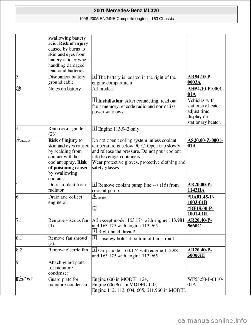
swallowing battery
acid. Risk of injury
caused by burns to
skin and eyes from
battery acid or when
handling damaged
lead-acid batteries
3Disconnect battery
ground cable The battery is located in the right of the
engine compartment.AR54.10-P-
0003A
Notes on batteryAll modelsAH54.10-P-0001-
01A
Installation: After connecting, read out
fault memory, encode radio and normalize
power windows.Vehicles with
stationary heater:
adjust time
display on
stationary heater.
4.1Remove air guide
(23) Engine 113.942 only.
Risk of injury to
skin and eyes caused
by scalding from
contact with hot
coolant spray. Risk
of poisoning caused
by swallowing
coolant.Do not open cooling system unless coolant
temperature is below 90° C. Open cap slowly
and release the pressure. Do not pour coolant
into beverage containers.
Wear protective gloves, pr otective clothing and
safety glasses.AS20.00-Z-0001-
01A
5Drain coolant from
radiator Remove coolant pump line --> (16) from
coolant pump.AR20.00-P-
1142HA
6Drain and collect
engine oil *BA01.45-P-
1003-01B
*BF18.00-P-
1001-01H
7.1Remove viscous fan
(1)All except model 163.174 with engine 113.981
and 163.175 with engine 113.965.
Right-hand thread!AR20.40-P-
5660C
8.1Remove fan shroud
(2). Unscrew bolts at bottom of fan shroud
8.2Remove electric fan Only model 163.174 with engine 113.981
and 163.175 with engine 113.965.AR20.40-P-
5000GH
9Attach guard plate
for radiator /
condenser
Guard plate for
radiator / condenserEngine 606 in MODEL 124,
Engine 606.961 in MODEL 140,
Engine 112, 113, 604, 605, 611.960 in MODEL WF58.50-P-0110-
01A
2001 Mercedes-Benz ML320
1998-2005 ENGINE Complete engine - 163 Chassis
me
Saturday, October 02, 2010 3:17:56 PMPage 53 © 2006 Mitchell Repair Information Company, LLC.
Page 2413 of 4133

two bottom bolts at transmission bell.
*BA27.40-P-
1008-01A
34Unscrew nuts (18)
for engine mount Before unscrewing left engine mount, press
oil line of power stee ring out of fixture.
*BA22.10-P-
1001-01L
35Unscrew oil filler
pipe (automatic
transmission) at right
cylinder head cover
36Attach engine hoist
to engine lifting eyes Use engine removal device!
*WE58.40-Z-
1012-11A
*WE58.40-Z-
1020-11A
37Raise engine Ensure that engine and its detachable
components are not lying against the body!
38Insert transmission
support (22) The transmission support is inserted onto
crossmember and into recess of transmission.
The transmission support prevents the
torque converter being pulled out. At the same
time, the transmission is fixed in place with the
transmission support when installing the
engine.
*WE58.40-Z-
1036-11A
?
*WE58.40-Z-
1036-11A
39Unscrew two top
bolts (engine 112) or
two bottom bolts
(engine 113) of
transmission bell Ensure that engine does not hit at front
against radiator or condenser damaging them
40Pull engine out
toward front and lift
out
41Install in the reverse
order
42Inspect cooling
system for leaks If fitting new cylinder head gaskets, bring
engine to operating temperature beforehand.AR20.00-P-
1010HA
43Risk of accident
caused by vehicle
starting off by itself Secure vehicle to prev ent it from moving by
itself.
Wear closed and snug-fitting work clothes. AS00.00-Z-0005-
01A
2001 Mercedes-Benz ML320
1998-2005 ENGINE Complete engine - 163 Chassis
me
Saturday, October 02, 2010 3:17:56 PMPage 57 © 2006 Mitchell Repair Information Company, LLC.
Page 2487 of 4133

Fig. 106: Identifying Oil Pan Remove/Install Components - Shown On Engine 112
Remove/install
External torx setFig. 49
1Remove oil pan bottom
section (1)Model 163.154/157/172.AR01.45-P-7555V
Model 163.174/175.AR01.45-P-7555VE
*BA01.45-P-1002-01B
2Disconnect electrical line
at oil sensor (oil level,
temperature and quality)
(B40) Remove cable strap at oil
pipe.
3Remove oil pipe (2) from
dipstick Installation: Replace the
sealing ring!AR18.40-P-3510BV
*BA01.20-P-1001-01E
4Remove oil pan top
section(3)Take out oil pan to the front in
direction of travel for this step;
rotate crankshaft slightly, if
necessary.
Installation: Observe
different bolt length and bolt
diameter: ?
Screw diagram of oil panAR01.45-P-7500-06F
Notes on application of
sealant to oil panEngine 112AH01.45-P-0001-01C
2001 Mercedes-Benz ML320
1998-2005 ENGINE Complete engine - 163 Chassis
me
Saturday, October 02, 2010 3:17:58 PMPage 131 © 2006 Mitchell Repair Information Company, LLC.
Page 2512 of 4133

AP18.00-P-0101-02Z
Extract engine oil
Commercially available tools
(see Workshop Equipment Manual)
Number
Designation
Make (e. g.)
Order number
WH58.30-Z-1007-16A
Engine oil extractor
Deutsche Tecalemit
Am Metallwerk 11
33659 Bielefeld
1.386950.2
P18.00-0019-01
Shown on Engine 104
1
Extract engine oil through the dipstick guide tube.
Perform only when engine is at normal operating temperature.
Copyright DaimlerChrysler AG 20.05.2006 CD-Ausgabe G/10/04 . This WIS print-out will not be recorde
d by Modification services.
Page 1
Page 2842 of 4133

Fig. 318: Identifying Active Service System (ASSYST) Display
ACTIVE SERVICE SYSTEM (ASSYST) INFLUENCING PARAMETERS - GF00.20-P-0003-05A
The values of various influencing parameters are required by ASSYST for calculating the demand-based service
interval, and these are included in the calculation of the service interval as weighting factors . There are two
versions within ASSYST, the difference being in the oil level sensors fitted:
The familiar oil level indicator switch (S43) is fitted to engines (104, 111, 119, 120, 602.982, 604, 605,
606). In view of the fact that this is a switch, it is only possible to detect if the oil level drops below the
minimum level.
The oil sensor (oil level/temperature/quality, B40) is used on more recent engines (e.g. 112, 113, 166,
611, 668). This sensor consists of 2 capacitor systems with the engine oil as an insulator. If the water
content of the oil or the oil level changes, there is a change in the capacitance of the "capacitor".
The capacitance is thus a measure for the oil level.
In addition, the oil sensor (oil level/temperature/quality, B40) contains a temperature sensor which
detects the temperature of the engine oil.
All the signals are processed in the electronics integrated in the sensor to form a PWM (pulse width
modulated) signal, and passed to the engine control module (N3).
In addition to the weighting factors, which depend on reallife driving conditions, quality factors are also used
for calculating the demand-based service interval (remaining distance and remaining time).
Survey of ASSYST influencing parameters
Weighting factors (dependant on reallife driving conditions):
Load torque
Engine speed
Oil level
Engine oil temperature
Oil correction factor (is used as comparative value for determining oil level)
Coolant temperature
These data are supplied by the injection system control module (N3) to the service microprocessor over
the CAN.
The data relating to oil level, engine oil temperature and oil correction factor are supplied by the oil
sensor (oil level/temperature/quality, B40) through the injection system control module (N3), and are
therefore only available on engines fitted with this sensor.
Quality factors (these are factory-set to base values and can be changed with the HHT, if operating
conditions of the vehicle so necessitate; they influence the start distance):
2004 Mercedes-Benz ML350
1998-2005 GENINFO Overall vehicle - 163 Chassis
me
Saturday, October 02, 2010 3:47:47 PMPage 197 © 2006 Mitchell Repair Information Company, LLC.
Page 2843 of 4133

Engine version factor (gasoline/diesel)
National factor (The kilometer or mileage is coded in accordance with the national version.)
Distance travelled :
ASSYST is supplied with the 4 wheel speeds from the traction systems control module (N47) over the
CAN for calculating the distance travelled.
Time
ASSYST is supplied with the time information from the clock integrated in the instrument cluster.
ACTIVE SERVICE SYSTEM (ASSYST) SURVEY MODEL/ENGINE/SENSOR/INSTRUMENT CLUSTER - GF00.20-P-0003-
06A
The table below (status: March 1999) lists the various vehicle models with the different engines and the
different oil level sensors.
In addition, the table also indicates whether an instrument cluster with multifunction display is fitted.
ModelEngineOil level sensorMultifunction display
with engine
129112, 113
103, 104, 119, 120Oil sensor (oil
level/temperature/quality, B40)
Oil level indicator switch S43-
140-
104, 119, 120, 606Oil sensor (oil
level/temperature/quality, B40)
Oil level indicator switch S43-
163112, 113, 612
111Oil sensor (oil
level/temperature/quality, B40)
Oil level indicator switch S43-
168166, 668
-Oil sensor (oil
level/temperature/quality, B40)
Oil level indicator switch S43-
170112
111Oil sensor (oil
level/temperature/quality, B40)
Oil level indicator switch S43-
202112, 113, 611
104, 111, 601, 604,
605Oil sensor (oil
level/temperature/quality, B40)
Oil level indicator switch S43-
208112, 113
111Oil sensor (oil
level/temperature/quality, B40)
Oil level indicator switch S43Engine 112 only and
Gulf States: engine 111
210112, 113, 611
104, 111, 602, 605,
606Oil sensor (oil
level/temperature/quality, B40)Engines 112,113 Gulf
States, , : on all
engines fitted; others:
2004 Mercedes-Benz ML350
1998-2005 GENINFO Overall vehicle - 163 Chassis
me
Saturday, October 02, 2010 3:47:47 PMPage 198 © 2006 Mitchell Repair Information Company, LLC.
Page 2845 of 4133

After a level has dropped below a warning threshold, the remaining distance or the remaining time is displayed
in text panel (b) and the tool symbol (a) appears in the display (top ill.). In addition, ASSYST features a low
engine oil level display. If the oil level is too low or too high, this appears in text panel (b) and the oil can
symbol (a) is displayed (bottom ill.).
( The illustrations relate to models with multifunction display. For other models, refer to document:
"ASSYST display facilities".)
Service A/B display
All models will feature an automatic display of the service (A or B) by no later than modification year 00/1.
More detailed information is contained in the document displaying service.
Fig. 320: Identifying Service A/B Display
In view of the complexity of the system, ASSYST features its own processor in the instrument cluster.
ASSYST is supplied with the time information from the electronic clock integrated in the instrument cluster.
The other data required are supplied over the CAN dataline by the traction systems control module (N47) and
by the injection system control module (N3).
CAN data required for ASSYST:
wheel speed signals for calculating the vehicle speed and distance (from traction systems control module,
N47)
Coolant temperature (from injection system control module, N3)
Engine oil temperature (from injection system control module, N3)
Oil level (from injection system control module, N3)
Engine speed (from injection system control module, N3)
Load torque (from injection system control module, N3)
Oil correction factor (from injection system control module, N3)
Active service system (ASSYST) GF00.20-P-0003-03A
2004 Mercedes-Benz ML350
1998-2005 GENINFO Overall vehicle - 163 Chassis
me
Saturday, October 02, 2010 3:47:47 PMPage 200 © 2006 Mitchell Repair Information Company, LLC.