bulb MERCEDES-BENZ ML350 1997 Complete Manual PDF
[x] Cancel search | Manufacturer: MERCEDES-BENZ, Model Year: 1997, Model line: ML350, Model: MERCEDES-BENZ ML350 1997Pages: 4133, PDF Size: 88.89 MB
Page 2034 of 4133
GF54.30-P-3007A
Charge indicator lamp, exterior lamp failure
24.10.96
MODEL
129, 140 as of 1.6.96,
163, 168, 170,
202 as of 1.8.96,
208 up to 31.7.99,
210 as of 1.6.96 up to 30.6.99
P54.30-0517-06
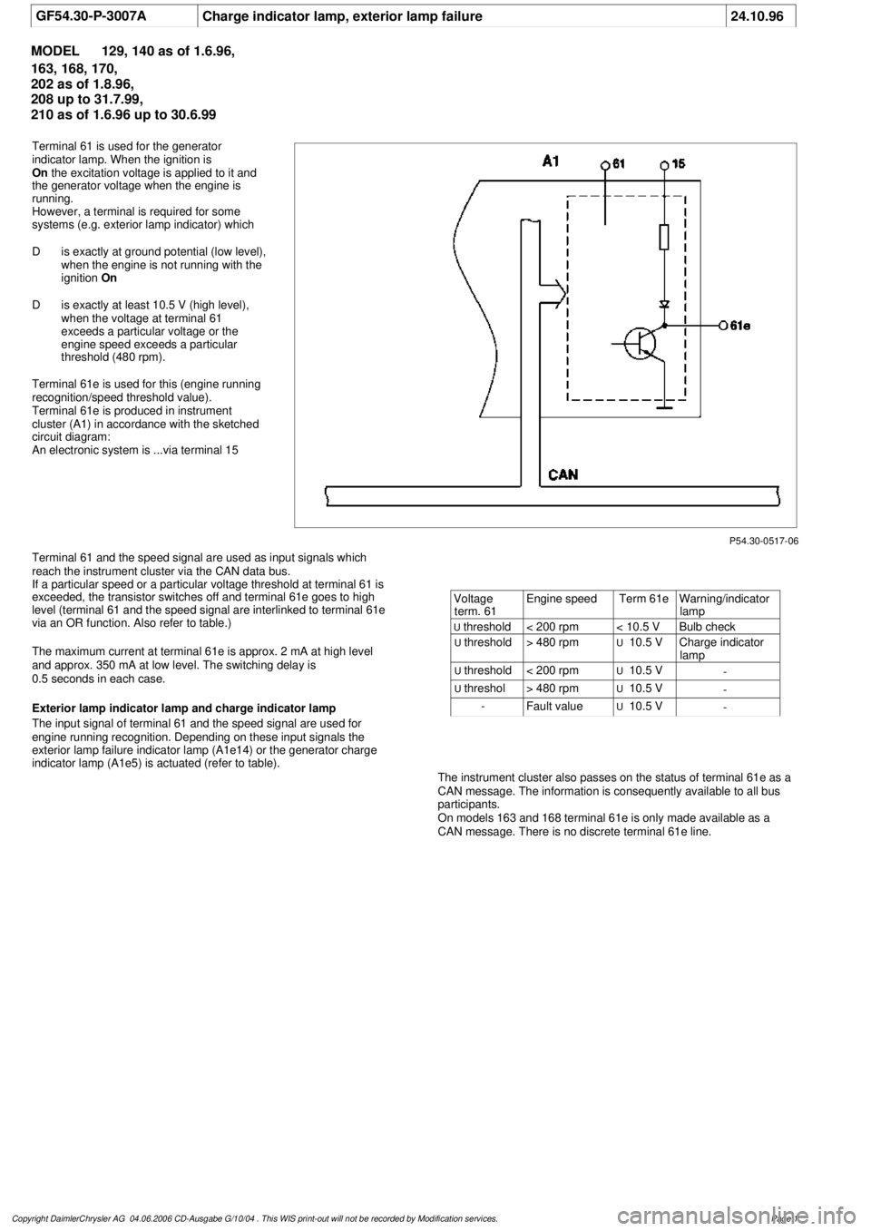
Terminal 61 is used for the generator
indicator lamp. When the ignition is
On
the excitation voltage is applied to it and
the generator voltage when the engine is
running.
However, a terminal is required for some
systems (e.g. exterior lamp indicator) which
D
is exactly at ground potential (low level),
when the engine is not running with the
ignition
On
D
is exactly at least 10.5 V (high level),
when the voltage at terminal 61
exceeds a particular voltage or the
engine speed exceeds a particular
threshold (480 rpm).
Terminal 61e is used for this (engine running
recognition/speed threshold value).
Terminal 61e is produced in instrument
cluster (A1) in accordance with the sketched
circuit diagram:
An electronic system is ...via terminal 15
Terminal 61 and the speed signal are used as input signals which
reach the instrument cluster via the CAN data bus.
If a particular speed or a particular voltage threshold at terminal 61 is
exceeded, the transistor switches off and terminal 61e goes to high
level (terminal 61 and the speed signal are interlinked to terminal 61e
via an OR function. Also refer to table.)
The maximum current at terminal 61e is approx. 2 mA at high level
and approx. 350 mA at low level. The switching delay is
0.5 seconds in each case.
Exterior lamp indicator lamp and charge indicator lamp
The input signal of terminal 61 and the speed signal are used for
engine running recognition. Depending on these input signals the
exterior lamp failure indicator lamp (A1e14) or the generator charge
indicator lamp (A1e5) is actuated (refer to table).
The instrument cluster also passes on the status of terminal 61e as a
CAN message. The information is consequently available to all bus
participants.
On models 163 and 168 terminal 61e is only made available as a
CAN message. There is no discrete terminal 61e line.
Voltage
term. 61
Engine speed
Term 61e
Warning/indicator
lamp
U
threshold
< 200 rpm
< 10.5 V
Bulb check
U
threshold
> 480 rpm
U
10.5 V
Charge indicator
lamp
U
threshold
< 200 rpm
U
10.5 V
-
U
threshol
> 480 rpm
U
10.5 V
-
-
Fault value
U
10.5 V
-
Copyright DaimlerChrysler AG 04.06.2006 CD-Ausgabe G/10/04 . This WIS print-out will not be recorde
d by Modification services.
Page 1
Page 2048 of 4133
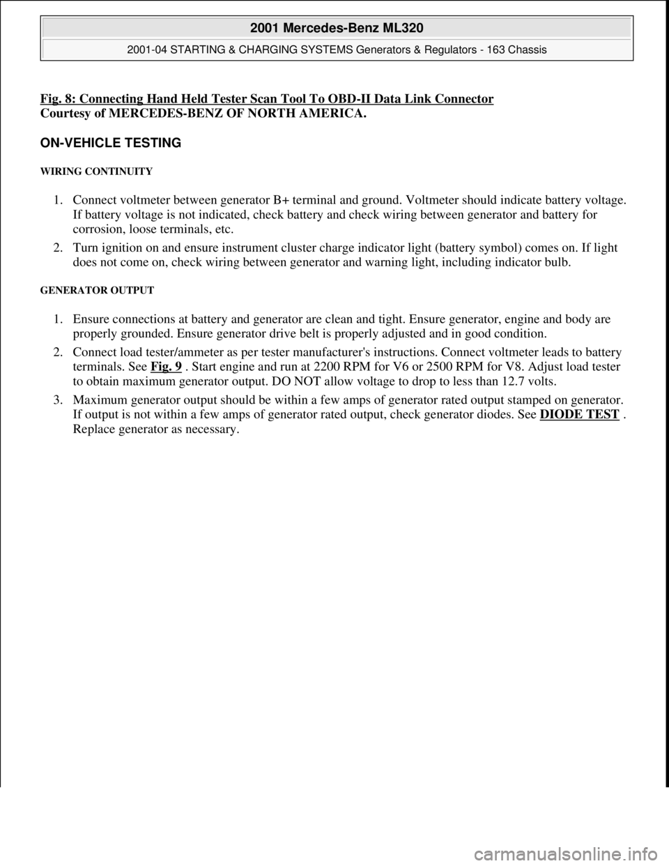
Fig. 8: Connecting Hand Held Tester Scan Tool To OBD-II Data Link Connector
Courtesy of MERCEDES-BENZ OF NORTH AMERICA.
ON-VEHICLE TESTING
WIRING CONTINUITY
1. Connect voltmeter between generator B+ terminal and ground. Voltmeter should indicate battery voltage.
If battery voltage is not indicated, check battery and check wiring between generator and battery for
corrosion, loose terminals, etc.
2. Turn ignition on and ensure instrument cluster charge indicator light (battery symbol) comes on. If light
does not come on, check wiring between generator and warning light, including indicator bulb.
GENERATOR OUTPUT
1. Ensure connections at battery and generator are clean and tight. Ensure generator, engine and body are
properly grounded. Ensure generator drive belt is properly adjusted and in good condition.
2. Connect load tester/ammeter as per tester manufacturer's instructions. Connect voltmeter leads to battery
terminals. See Fig. 9
. Start engine and run at 2200 RPM for V6 or 2500 RPM for V8. Adjust load tester
to obtain maximum generator output. DO NOT allow voltage to drop to less than 12.7 volts.
3. Maximum generator output should be within a few amps of generator rated output stamped on generator.
If output is not within a few amps of generator rated output, check generator diodes. See DIODE TEST
.
Replace
generator as necessary.
2001 Mercedes-Benz ML320
2001-04 STARTING & CHARGING SYSTEMS Generators & Regulators - 163 Chassis
me
Saturday, October 02, 2010 3:20:32 PMPage 14 © 2006 Mitchell Repair Information Company, LLC.
Page 2109 of 4133
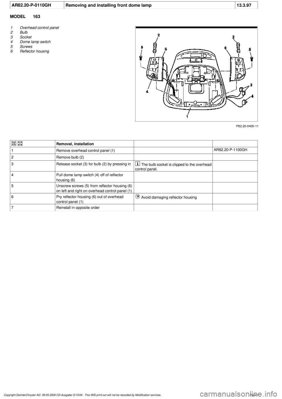
AR82.20-P-0110GH
Removing and installing front dome lamp
13.3.97
MODEL
163
P82.20-0400-11
1
Overhead control panel
2
Bulb
3
Socket
4
Dome lamp switch
5
Screws
6
Reflector housing
Removal, installation
1
Remove overhead control panel (1)
AR82.20-P-1100GH
2
Remove bulb (2)
3
Release socket (3) for bulb (2) by pressing in
The bulb socket is clipped to the overhead
control panel.
4
Pull dome lamp switch (4) off of reflector
housing (6)
5
Unscrew screws (5) from reflector housing (6)
on left and right on overhead control panel (1)
6
Pry reflector housing (6) out of overhead
control panel (1)
Avoid damaging reflector housing
7
Reinstall in opposite order
Copyright DaimlerChrysler AG 09.05.2006 CD-Ausgabe G/10/04 . This WIS print-out will not be recorde
d by Modification services.
Page 1
Page 2514 of 4133
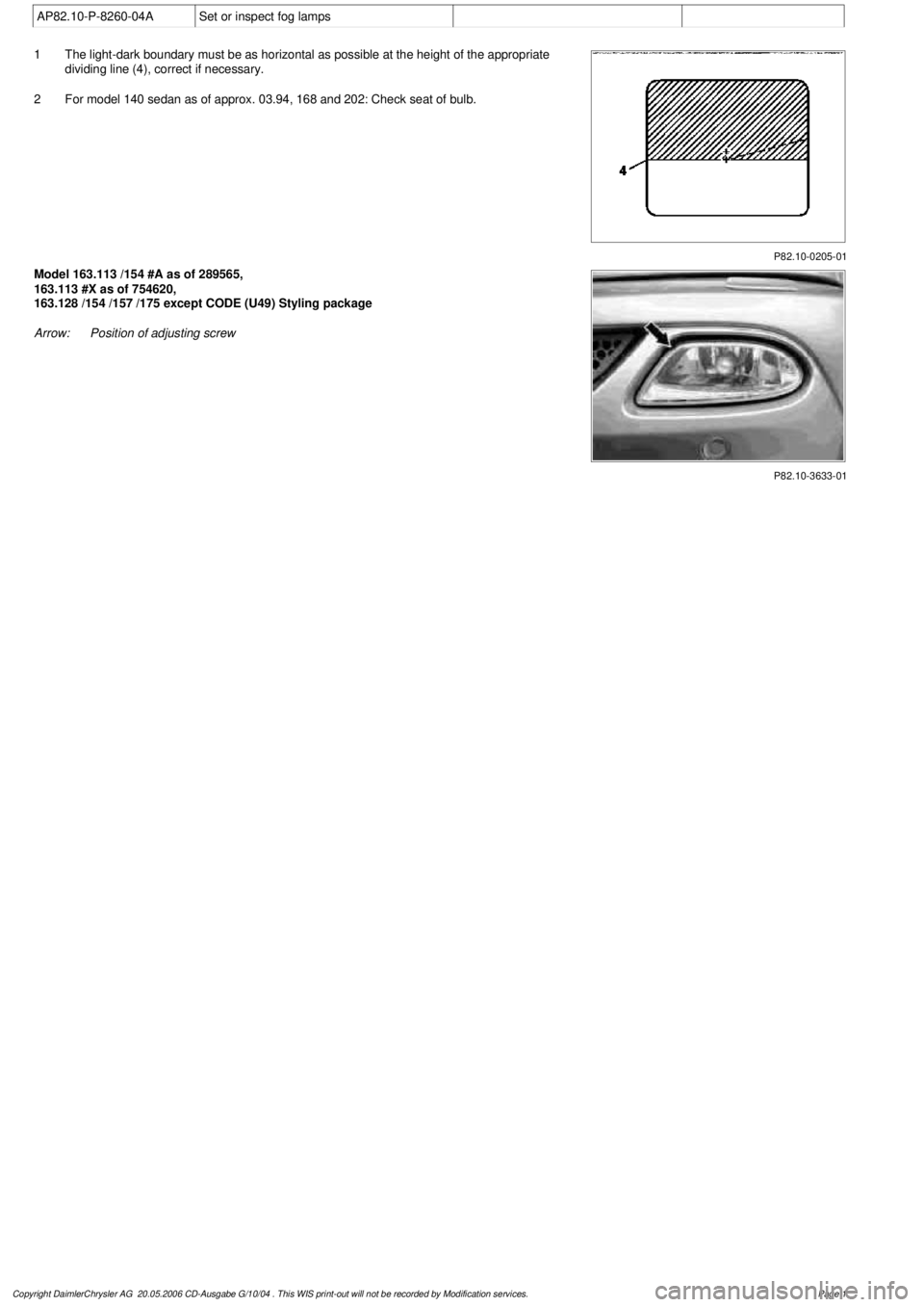
AP82.10-P-8260-04A
Set or inspect fog lamps
P82.10-0205-01
1
The light-dark boundary must be as horizontal as possible at the height of the appropriate
dividing line (4), correct if necessary.
2
For model 140 sedan as of approx. 03.94, 168 and 202: Check seat of bulb.
P82.10-3633-01
Model 163.113 /154 #A as of 289565,
163.113 #X as of 754620,
163.128 /154 /157 /175 except CODE (U49) Styling package
Arrow:
Position of adjusting screw
Copyright DaimlerChrysler AG 20.05.2006 CD-Ausgabe G/10/04 . This WIS print-out will not be recorde
d by Modification services.
Page 1
Page 3419 of 4133
TESTING & REPAIR
TESTING AND REPAIR WORK: PASSENGER CARS: CLIMATE CONTROL - AR83.00-Z-9163AA
MODEL 163
electrical system testing6000-07GH
8
Refrigerant compressor actuation, air
conditioning (Tempmatic) electrical
system testing
AD83.30-P-
6000-08GH
9
Refrigerant pressure sensor, air
conditioning (Tempmatic) electrical
system testing
AD83.30-P-
6000-09GH
10
Ambient temperature sensor, air
conditioning (Tempmatic) electrical
system testing
as of 01.12.99AD83.30-P-
6000-24GH
Remove/install center outlet flap
actuator motorMODEL 163...AR83.10-P-
2019GH
Removing and installing rear air
nozzleMODEL 163.113/154 /174 #A as of 289565, 163.113 #X
as of 754620, 163.128 /157 /175AR83.10-P-
4800GH
Remove, install switch unit for
heater/ ventilationMODELS 163.113/136/154/172/174 up to 31.8.01 with
CODE (580) air conditioning or Tempmatic for USAAR83.20-P-
1835GH
Remove and install heat
exchanger from heater housingMODEL 163AR83.20-P-
3400GH
Replace bulbs in push-button
control moduleMODELS 163.113/154/174/136/172 up to 31.8.01AR83.25-P-
1123GH
Remove and install series
resistor for heater blowerMODEL 163.113/128 /136 /154 /157 /172 /174 /175AR83.25-P-
1250GH
Remove/install cover at air
intakeMODEL 163.113/128 /136 /154 /157 /172 /174 /175AR83.25-P-
1405GH
Carry out quick test on air
conditioning systemMODEL 163, 901, 902, 903, 904 ...AR83.30-
D-1209A
Draining, evacuating and
refilling air conditioning,
checking function and checking
for leaks
MODEL 163...AR83.30-P-
1760GH
Remove/install defroster vent
flap actuator motor for
windshieldMODEL 163.113/154 /174 #A as of 289565, 163.113 #X
as of 754620, 163.128 /157 /175AR83.30-P-
2006GH
Remove/install footwell flap
actuator motorMODEL 163...AR83.30-P-
2007GH
Remove/install rear shutoff flap
actuator motorMODEL 163.113/154 /174 #A as of 289565, 163.113 #X
as of 754620, 163.128 /157 /175AR83.30-P-
2008GH
2001 Mercedes-Benz ML320
1998-2005 HVAC Climate Control - 163 Chassis
me
Saturday, October 02, 2010 3:23:17 PMPage 175 © 2006 Mitchell Repair Information Company, LLC.
Page 3425 of 4133
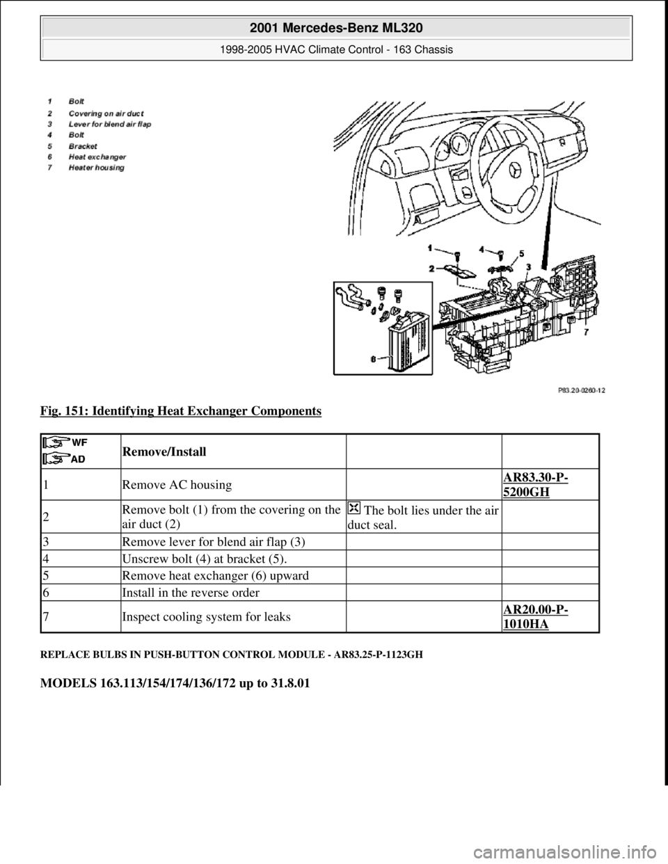
Fig. 151: Identifying Heat Exchanger Components
REPLACE BULBS IN PUSH-BUTTON CONTROL MODULE - AR83.25-P-1123GH
MODELS 163.113/154/174/136/172 up to 31.8.01
Remove/Install
1Remove AC housing AR83.30-P-
5200GH
2Remove bolt (1) from the covering on the
air duct (2)The bolt lies under the air
duct seal.
3Remove lever for blend air flap (3)
4Unscrew bolt (4) at bracket (5).
5Remove heat exchanger (6) upward
6Install in the reverse order
7Inspect cooling system for leaks AR20.00-P-
1010HA
2001 Mercedes-Benz ML320
1998-2005 HVAC Climate Control - 163 Chassis
me
Saturday, October 02, 2010 3:23:18 PMPage 181 © 2006 Mitchell Repair Information Company, LLC.
Page 3426 of 4133
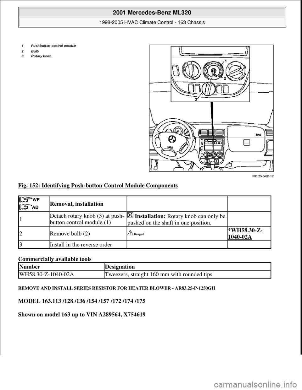
Fig. 152: Identifying Push-button Control Module Components
Commercially available tools
REMOVE AND INSTALL SERIES RESISTOR FOR HEATER BLOWER - AR83.25-P-1250GH
MODEL 163.113 /128 /136 /154 /157 /172 /174 /175
Shown on model 163 up to VIN A289564, X754619
Removal, installation
1Detach rotary knob (3) at push-
button control module (1) Installation: Rotary knob can only be
pushed on the shaft in one position.
2Remove bulb (2) *WH58.30-Z-
1040-02A
3Install in the reverse order
NumberDesignation
WH58.30-Z-1040-02ATweezers, straight 160 mm with rounded tips
2001 Mercedes-Benz ML320
1998-2005 HVAC Climate Control - 163 Chassis
me
Saturday, October 02, 2010 3:23:18 PMPage 182 © 2006 Mitchell Repair Information Company, LLC.
Page 3488 of 4133
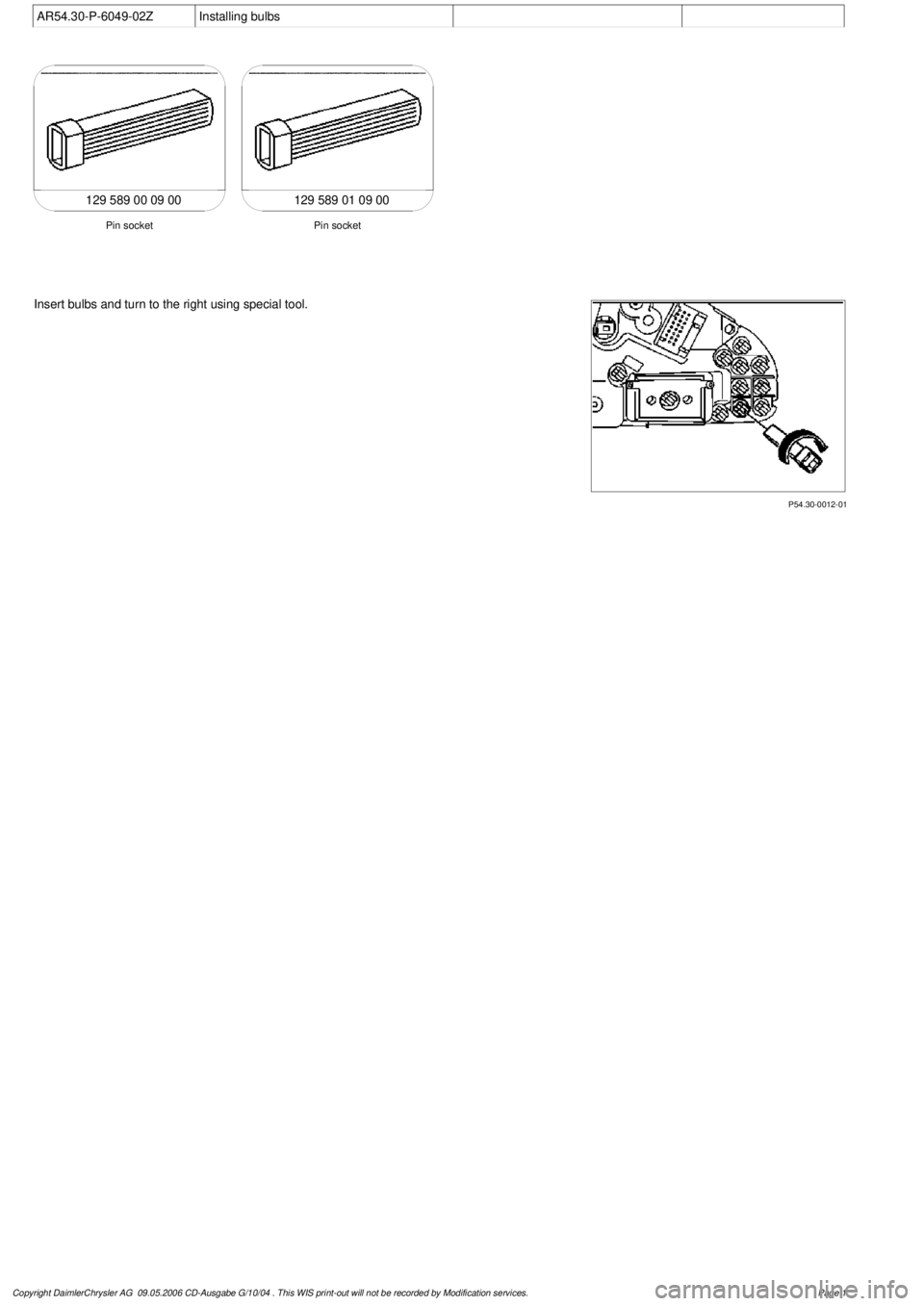
AR54.30-P-6049-02Z
Installing bulbs
129 589 00 09 00129 589 01 09 00
Pin socket
Pin socket
P54.30-0012-01
Insert bulbs and turn to the right using special tool.
Copyright DaimlerChrysler AG 09.05.2006 CD-Ausgabe G/10/04 . This WIS print-out will not be recorde
d by Modification services.
Page 1
Page 3489 of 4133
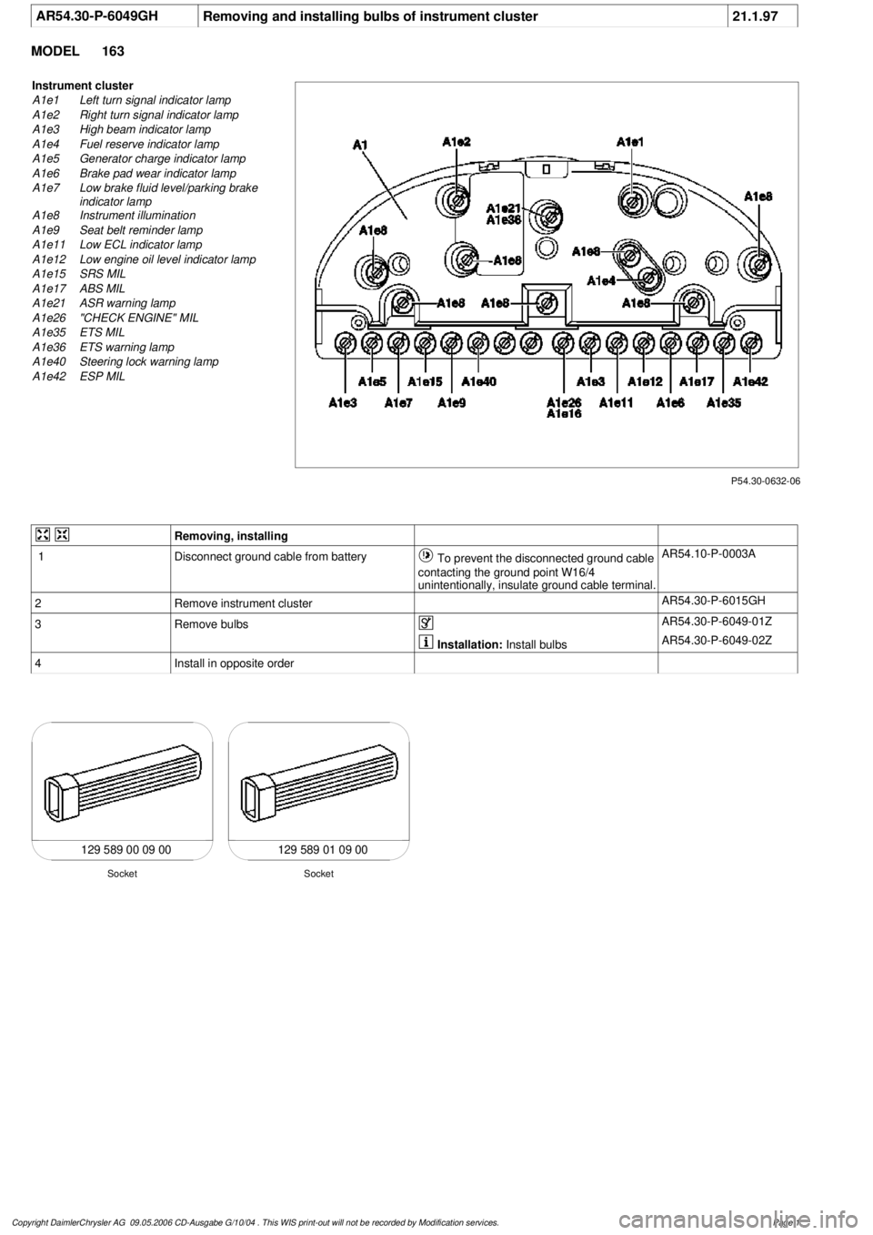
AR54.30-P-6049GH
Removing and installing bulbs of instrument cluster
21.1.97
MODEL
163
P54.30-0632-06
Instrument cluster
A1e1
Left turn signal indicator lamp
A1e2
Right turn signal indicator lamp
A1e3
High beam indicator lamp
A1e4
Fuel reserve indicator lamp
A1e5
Generator charge indicator lamp
A1e6
Brake pad wear indicator lamp
A1e7
Low brake fluid level/parking brake
indicator lamp
A1e8
Instrument illumination
A1e9
Seat belt reminder lamp
A1e11
Low ECL indicator lamp
A1e12
Low engine oil level indicator lamp
A1e15
SRS MIL
A1e17
ABS MIL
A1e21
ASR warning lamp
A1e26
"CHECK ENGINE" MIL
A1e35
ETS MIL
A1e36
ETS warning lamp
A1e40
Steering lock warning lamp
A1e42
ESP MIL
Removing, installing
1
Disconnect ground cable from battery
To prevent the disconnected ground cable
contacting the ground point W16/4
unintentionally, insulate ground cable terminal.
AR54.10-P-0003A
2
Remove instrument cluster
AR54.30-P-6015GH
3
Remove bulbs
AR54.30-P-6049-01Z
Installation:
Install bulbs
AR54.30-P-6049-02Z
4
Install in opposite order
129 589 00 09 00 129 589 01 09 00
Socket
Socket
Copyright DaimlerChrysler AG 09.05.2006 CD-Ausgabe G/10/04 . This WIS print-out will not be recorde
d by Modification services.
Page 1
Page 3490 of 4133
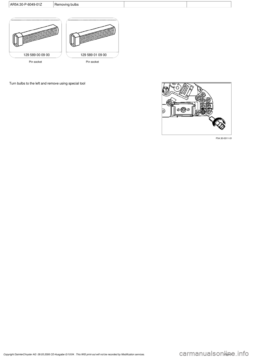
AR54.30-P-6049-01Z
Removing bulbs
129 589 00 09 00129 589 01 09 00
Pin socket
Pin socket
P54.30-0011-01
Turn bulbs to the left and remove using special tool
Copyright DaimlerChrysler AG 09.05.2006 CD-Ausgabe G/10/04 . This WIS print-out will not be recorde
d by Modification services.
Page 1