Sd card MERCEDES-BENZ ML350 2010 W164 User Guide
[x] Cancel search | Manufacturer: MERCEDES-BENZ, Model Year: 2010, Model line: ML350, Model: MERCEDES-BENZ ML350 2010 W164Pages: 368, PDF Size: 9.09 MB
Page 225 of 368
iThe recommended tire inflation pressures
for your vehicle can be found on
R the Tire and Loading Information placard
located on the driver’s door B-pillar
( Y page 227)
R the tire inflation pressure label on the
inside of the fuel filler flap
The tire inflation pressures are not listed in
the Operator’s Manual.GWarning!
The tire pressure loss warning system does
not provide a warning for wrongly selected tire
inflation pressures. Always adjust tire
inflation pressure according to the Tire and
Loading Information placard on the driver’s
door B-pillar or on the tire inflation pressure
label located on the inside of the fuel filler flap.
The tire pressure loss warning system does
not replace regular checks of the tire inflation
pressures since a gradual pressure loss in
more than one tire cannot be detected by the
tire pressure loss warning system.
The tire pressure loss warning system is not
able to issue a warning due to a sudden
dramatic loss of tire inflation pressure (e.g.
tire blowout caused by a foreign object). In
this case bring the vehicle to a halt by carefully
applying the brakes and avoiding abrupt
steering maneuvers.
Restarting the tire pressure loss warning
system
The tire pressure loss warning system must
be restarted in the following situations:
R after you have changed the tire inflation
pressure
R after you have replaced the wheels or tires
R after you have installed new wheels or tires
XUsing the Tire and Loading Information
placard on the driver’s door B-pillar or, if
available, the tire inflation pressure label on
the inside of the fuel filler flap, make sure
the tire inflation pressure of all four tires is
correct.GWarning!
The tire pressure loss warning system can
only warn you in a reliable manner if you have
set the correct tire inflation pressures for
each tire.
If an incorrect tire inflation pressure was set,
the system will monitor the pressure
according to the incorrect value.
XSwitch on the ignition.XMake sure the standard display appears in
the multifunction display ( Y page 122).XPress button * or & on the
multifunction steering wheel repeatedly
until the following message appears in the
multifunction display:
Run Flat Indicator
Active
Menu: R-ButtonXPress the reset button ( Y page 118).
The following message will appear in the
multifunction display:
Restart
Run Flat Indicator?XIf you wish to confirm: Press button
W .
The following message will appear in the
multifunction display:
Run Flat Indicator
Restarted
After a certain “learning phase”, the tire
pressure loss warning system checks the
set pressure values for all four tires.XIf you wish to cancel: Press button X.
Advanced Tire Pressure Monitoring
System (Advanced TPMS), (USA only)
Your vehicle is equipped with the Advanced
Tire Pressure Monitoring System (Advanced
TPMS). It measures the tire inflation pressure
in the vehicle’s tires and issues warnings in
case of pressure loss in one or more of the
tires.
Tires and wheels223Operation164_AKB; 7; 31, en-USd2ureepe,Version: 2.11.8.12009-09-11T12:07:36+02:00 - Seite 223Z
Page 226 of 368
The TPMS is equipped with a combination low
tire pressure/ TPMS malfunction telltale in
the instrument cluster. Depending on how the
telltale illuminates, it indicates a low tire
pressure condition or a malfunction in the
TPMS system itself:
R If the telltale illuminates continuously, one
or more of your tires is significantly
underinflated. There is no malfunction in
the TPMS.
R If the telltale flashes for 60 seconds and
then stays illuminated, the TPMS system
itself is not operating properly.
The TPMS only functions on wheels that are
equipped with the proper electronic sensors.GWarning!
The TPMS does not indicate a warning for
wrongly selected inflation pressures. Always
adjust tire inflation pressure according to the
Tire and Loading Information placard or the
supplemental tire inflation pressure
information on the inside of the fuel filler flap.
The TPMS is not able to issue a warning due
to a sudden dramatic loss of pressure (e.g. tire
blowout caused by a foreign object). In this
case bring the vehicle to a halt by carefully
applying the brakes and avoiding abrupt
steering maneuvers.
GWarning!
Each tire, including the spare (if provided),
should be checked at least once a month
when cold and inflated to the inflation
pressure recommended by the vehicle
manufacturer on the Tire and Loading
Information placard on the driver’s door B-
pillar or the tire inflation pressure label on the
inside of the fuel filler flap. If your vehicle has
tires of a different size than the size indicated
on the Tire and Loading Information placard
or the tire inflation pressure label, you should
determine the proper tire inflation pressure
for those tires.
As an added safety feature, your vehicle has
been equipped with a tire pressure monitoring
system (TPMS) that illuminates a low tire
pressure telltale when one or more of your
tires are significantly underinflated.
Accordingly, when the low tire pressure
telltale illuminates, you should stop and check
your tires as soon as possible, and inflate
them to the proper pressure. Driving on a
significantly underinflated tire causes the tire
to overheat and can lead to tire failure.
Underinflation also reduces fuel efficiency
and tire tread life, and may affect the vehicle’s
handling and stopping ability. Please note that
the TPMS is not a substitute for proper tire
maintenance, and it is the driver’s
responsibility to maintain correct tire
pressure, even if underinflation has not
reached the level to trigger illumination of the
TPMS low tire pressure telltale.
Your vehicle has also been equipped with a
TPMS malfunction indicator to indicate when
the system is not operating properly. The
TPMS malfunction indicator is combined with
the low tire pressure telltale. When the
system detects a malfunction, the telltale will
flash for approximately 1 minute and then
remain continuously illuminated. This
sequence will continue upon subsequent
vehicle start-ups as long as the malfunction
exists. When the malfunction indicator is
illuminated, the system may not be able to
detect or signal low tire pressure as intended.
TPMS malfunctions may occur for a variety of
reasons, including the installation of
incompatible replacement or alternate tires
or wheels on the vehicle that prevent the
TPMS from functioning properly. Always
check the TPMS malfunction telltale after
replacing one or more tires or wheels on your
vehicle to ensure that the replacement or
alternate tires and wheels allow the TPMS to
continue to function properly.
i If a condition causing the TPMS to
malfunction develops, it may take up to
10 minutes for the system to signal a224Tires and wheelsOperation
164_AKB; 7; 31, en-USd2ureepe,Version: 2.11.8.12009-09-11T12:07:36+02:00 - Seite 224
Page 228 of 368
The respective tire is indicated by a red
rectangle.
Restarting Advanced TPMSGWarning!
It is the driver’s responsibility to set the tire
inflation pressure to the recommended cold
tire inflation pressure. Underinflated tires
affect the ability to steer or brake the vehicle.
You might lose control over the vehicle.
When you restart the TPMS, the system sets
new reference values for each tire.
The TPMS must be restarted when you have
adjusted the tire inflation pressure to a new
level (e.g. because of different load or driving
conditions). The TPMS is then recalibrated to
the current tire inflation pressures.
Restart the TPMS after adjusting the tire
inflation pressure to the inflation pressure
recommended for the vehicle operating
condition. Tire pressure should only be
adjusted on cold tires. Observe the
recommended tire inflation pressure on the
Tire and Loading Information placard on the
driver’s door B-pillar. Some vehicles may have
supplemental tire pressure information for
driving at high speeds or for vehicle loads less
than the maximum loaded vehicle condition.
If such information is provided, it can be
found on the inside of the fuel filler flap.
XUsing the Tire and Loading Information
placard on the driver’s door B-pillar
( Y page 227) or the supplemental tire
inflation pressure information on the inside
of the fuel filler flap, make sure the tire
inflation pressure of all four tires is correct.XSwitch on the ignition.XPress button V or U on the
multifunction steering wheel repeatedly
until the standard display appears in the
multifunction display ( Y page 122).XPress button & or * repeatedly until
you see the current inflation pressures for
each tire appear in the display or the
following message appears in the
multifunction display: Tire pressure
displayed after
driving for
a few minutes.XPress the reset button ( Y page 117).
The following message will appear in the
multifunction display:
Restart tire
pressure monitor?XIf you wish to confirm: Press button
W .
The following message will appear in the
multifunction display:
Tire Pressure Monitor
Restarted
After driving a few minutes the system
verifies that the current tire inflation
pressures are within the system’s specified
range. Afterwards the current tire inflation
pressures are accepted as reference values
and then monitored.XIf you wish to cancel: Press button X.
i
When the wheel positions have been
changed, the inflation pressure of a tire
may be displayed for the wrong position
temporarily. After driving for a few minutes,
the inflation pressure will be shown for the
correct position.
Maximum tire inflation pressure
GWarning!
Never exceed the maximum tire inflation
pressure. Follow recommended tire inflation
pressures.
Do not underinflate tires. Underinflated tires
wear excessively and/or unevenly, adversely
affect handling and fuel economy, and are
more likely to fail from being overheated.
Do not overinflate tires. Overinflated tires can
adversely affect handling and ride comfort,
wear unevenly, increase stopping distance,
and result in sudden deflation (blowout)
because they are more likely to become
226Tires and wheelsOperation
164_AKB; 7; 31, en-USd2ureepe,Version: 2.11.8.12009-09-11T12:07:36+02:00 - Seite 226
Page 229 of 368
punctured or damaged by road debris,
potholes etc.
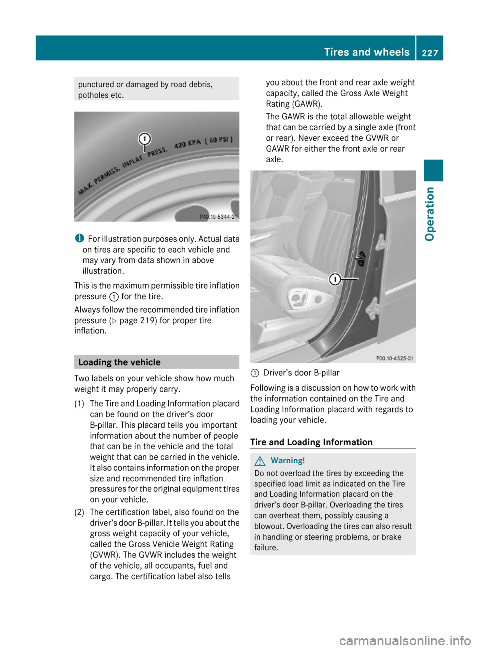
iFor illustration purposes only. Actual data
on tires are specific to each vehicle and
may vary from data shown in above
illustration.
This is the maximum permissible tire inflation
pressure : for the tire.
Always follow the recommended tire inflation
pressure (Y page 219) for proper tire
inflation.
Loading the vehicle
Two labels on your vehicle show how much
weight it may properly carry.
(1)The Tire and Loading Information placard
can be found on the driver’s door
B-pillar. This placard tells you important
information about the number of people
that can be in the vehicle and the total
weight that can be carried in the vehicle.
It also contains information on the proper
size and recommended tire inflation
pressures for the original equipment tires
on your vehicle.
(2)The certification label, also found on the
driver’s door B-pillar. It tells you about the
gross weight capacity of your vehicle,
called the Gross Vehicle Weight Rating
(GVWR). The GVWR includes the weight
of the vehicle, all occupants, fuel and
cargo. The certification label also tells
you about the front and rear axle weight
capacity, called the Gross Axle Weight
Rating (GAWR).
The GAWR is the total allowable weight
that can be carried by a single axle (front
or rear). Never exceed the GVWR or
GAWR for either the front axle or rear
axle.
:Driver’s door B-pillar
Following is a discussion on how to work with
the information contained on the Tire and
Loading Information placard with regards to
loading your vehicle.
Tire and Loading Information
GWarning!
Do not overload the tires by exceeding the
specified load limit as indicated on the Tire
and Loading Information placard on the
driver’s door B-pillar. Overloading the tires
can overheat them, possibly causing a
blowout. Overloading the tires can also result
in handling or steering problems, or brake
failure.
Tires and wheels227Operation164_AKB; 7; 31, en-USd2ureepe,Version: 2.11.8.12009-09-11T12:07:36+02:00 - Seite 227Z
Page 230 of 368
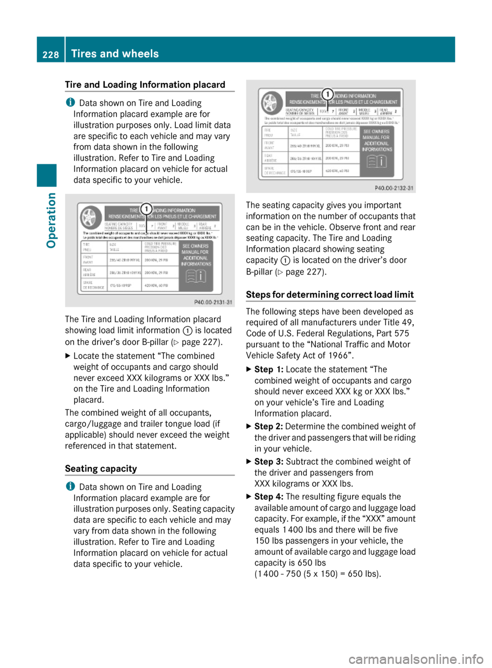
Tire and Loading Information placard
iData shown on Tire and Loading
Information placard example are for
illustration purposes only. Load limit data
are specific to each vehicle and may vary
from data shown in the following
illustration. Refer to Tire and Loading
Information placard on vehicle for actual
data specific to your vehicle.
The Tire and Loading Information placard
showing load limit information : is located
on the driver’s door B-pillar (Y page 227).
XLocate the statement “The combined
weight of occupants and cargo should
never exceed XXX kilograms or XXX lbs.”
on the Tire and Loading Information
placard.
The combined weight of all occupants,
cargo/luggage and trailer tongue load (if
applicable) should never exceed the weight
referenced in that statement.
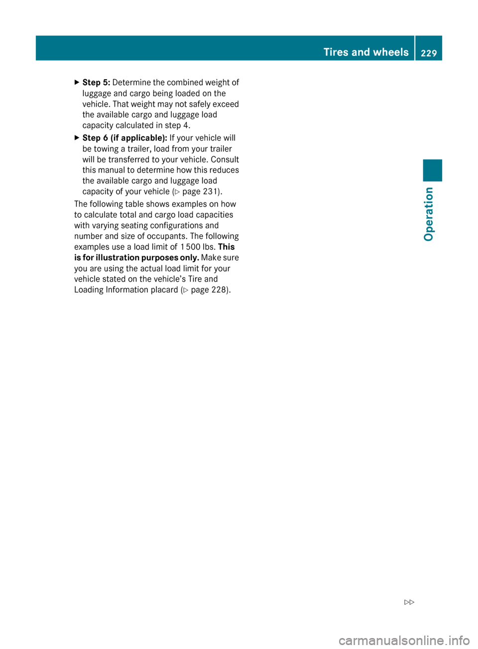
Seating capacity
iData shown on Tire and Loading
Information placard example are for
illustration purposes only. Seating capacity
data are specific to each vehicle and may
vary from data shown in the following
illustration. Refer to Tire and Loading
Information placard on vehicle for actual
data specific to your vehicle.
The seating capacity gives you important
information on the number of occupants that
can be in the vehicle. Observe front and rear
seating capacity. The Tire and Loading
Information placard showing seating
capacity : is located on the driver’s door
B-pillar (Y page 227).
Steps for determining correct load limit
The following steps have been developed as
required of all manufacturers under Title 49,
Code of U.S. Federal Regulations, Part 575
pursuant to the “National Traffic and Motor
Vehicle Safety Act of 1966”.
XStep 1: Locate the statement “The
combined weight of occupants and cargo
should never exceed XXX kg or XXX lbs.”
on your vehicle’s Tire and Loading
Information placard.
XStep 2: Determine the combined weight of
the driver and passengers that will be riding
in your vehicle.
XStep 3: Subtract the combined weight of
the driver and passengers from
XXX kilograms or XXX lbs.
XStep 4: The resulting figure equals the
available amount of cargo and luggage load
capacity. For example, if the “XXX” amount
equals 1 400 lbs and there will be five
150 lbs passengers in your vehicle, the
amount of available cargo and luggage load
capacity is 650 lbs
(1 400 - 750 (5 x 150) = 650 lbs).
228Tires and wheelsOperation
164_AKB; 7; 31, en-USd2ureepe,Version: 2.11.8.12009-09-11T12:07:36+02:00 - Seite 228
Page 231 of 368
XStep 5: Determine the combined weight of
luggage and cargo being loaded on the
vehicle. That weight may not safely exceed
the available cargo and luggage load
capacity calculated in step 4.XStep 6 (if applicable): If your vehicle will
be towing a trailer, load from your trailer
will be transferred to your vehicle. Consult
this manual to determine how this reduces
the available cargo and luggage load
capacity of your vehicle ( Y page 231).
The following table shows examples on how
to calculate total and cargo load capacities
with varying seating configurations and
number and size of occupants. The following
examples use a load limit of 1 500 lbs. This
is for illustration purposes only. Make sure
you are using the actual load limit for your
vehicle stated on the vehicle’s Tire and
Loading Information placard ( Y page 228).
Tires and wheels229Operation164_AKB; 7; 31, en-USd2ureepe,Version: 2.11.8.12009-09-11T12:07:36+02:00 - Seite 229Z
Page 232 of 368
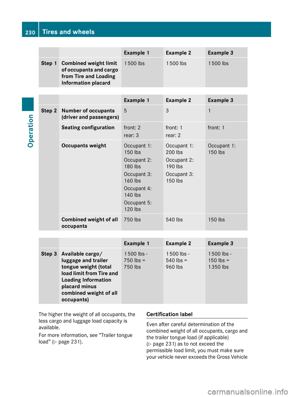
Example 1Example 2Example 3Step 1Combined weight limit
of occupants and cargo
from Tire and Loading
Information placard1 500 lbs1 500 lbs1 500 lbsExample 1Example 2Example 3Step 2Number of occupants
(driver and passengers)531Seating configurationfront: 2
rear: 3front: 1
rear: 2front: 1Occupants weightOccupant 1:
150 lbs
Occupant 2:
180 lbs
Occupant 3:
160 lbs
Occupant 4:
140 lbs
Occupant 5:
120 lbsOccupant 1:
200 lbs
Occupant 2:
190 lbs
Occupant 3:
150 lbsOccupant 1:
150 lbsCombined weight of all
occupants750 lbs540 lbs150 lbsExample 1Example 2Example 3Step 3Available cargo/
luggage and trailer
tongue weight (total
load limit from Tire and
Loading Information
placard minus
combined weight of all
occupants)1 500 lbs -
750 lbs =
750 lbs1 500 lbs -
540 lbs =
960 lbs1 500 lbs -
150 lbs =
1 350 lbsThe higher the weight of all occupants, the
less cargo and luggage load capacity is
available.
For more information, see “Trailer tongue
load” ( Y page 231).Certification label
Even after careful determination of the
combined weight of all occupants, cargo and
the trailer tongue load (if applicable)
( Y page 231) as to not exceed the
permissible load limit, you must make sure
your vehicle never exceeds the Gross Vehicle
230Tires and wheelsOperation
164_AKB; 7; 31, en-USd2ureepe,Version: 2.11.8.12009-09-11T12:07:36+02:00 - Seite 230
Page 233 of 368
Weight Rating (GVWR) and the Gross Axle
Weight Rating (GAWR) for either the front or
rear axle. You can obtain the GVWR and
GAWR from the certification label. The
certification label can be found on the driver’s
door B-pillar, see the “Technical data” section
(Y page 346).
Gross Vehicle Weight Rating (GVWR): The
total weight of the vehicle, all occupants, all
cargo, and the trailer tongue load (if
applicable) must never exceed the GVWR.
Gross Axle Weight Rating (GAWR): The total
allowable weight that can be carried by a
single axle (front or rear).
To assure that your vehicle does not exceed
the maximum permissible weight limits
(GVWR and GAWR for front and rear axle),
have the loaded vehicle (including driver,
passengers and all cargo and, if applicable,
trailer fully loaded) weighed on a suitable
commercial scale.
Trailer tongue load
The tongue load of any trailer is an important
weight to measure because it affects the load
you can carry in your vehicle. If a trailer is
towed, the tongue load must be added to the
weight of all occupants riding and any cargo
you are carrying in the vehicle. The tongue
load typically is between 8% and 15% of the
trailer weight and everything loaded in it.
Maximum tire load
GWarning!
Do not overload the tires by exceeding the
specified load limit as indicated on the Tire
and Loading Information placard on the
driver’s door B-pillar. Overloading the tires
can overheat them, possibly causing a
blowout. Overloading the tires can also result
in handling or steering problems, or brake
failure.
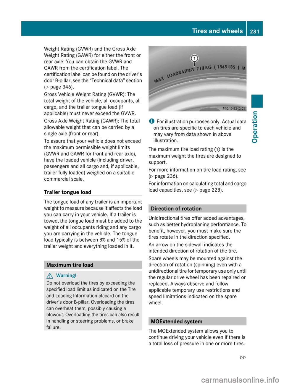
iFor illustration purposes only. Actual data
on tires are specific to each vehicle and
may vary from data shown in above
illustration.
The maximum tire load rating : is the
maximum weight the tires are designed to
support.
For more information on tire load rating, see
(Y page 236).
For information on calculating total and cargo
load capacities, see (Y page 228).
Direction of rotation
Unidirectional tires offer added advantages,
such as better hydroplaning performance. To
benefit, however, you must make sure the
tires rotate in the direction specified.
An arrow on the sidewall indicates the
intended direction of rotation of the tire.
Spare wheels may be mounted against the
direction of rotation (spinning) even with a
unidirectional tire for temporary use only until
the regular drive wheel has been repaired or
replaced. Always observe and follow
applicable temporary use restrictions and
speed limitations indicated on the spare
wheel.
MOExtended system
The MOExtended system allows you to
continue driving your vehicle even if there is
a total loss of pressure in one or more tires.
Tires and wheels231Operation164_AKB; 7; 31, en-USd2ureepe,Version: 2.11.8.12009-09-11T12:07:36+02:00 - Seite 231Z
Page 238 of 368
Tire size designation, load and speed
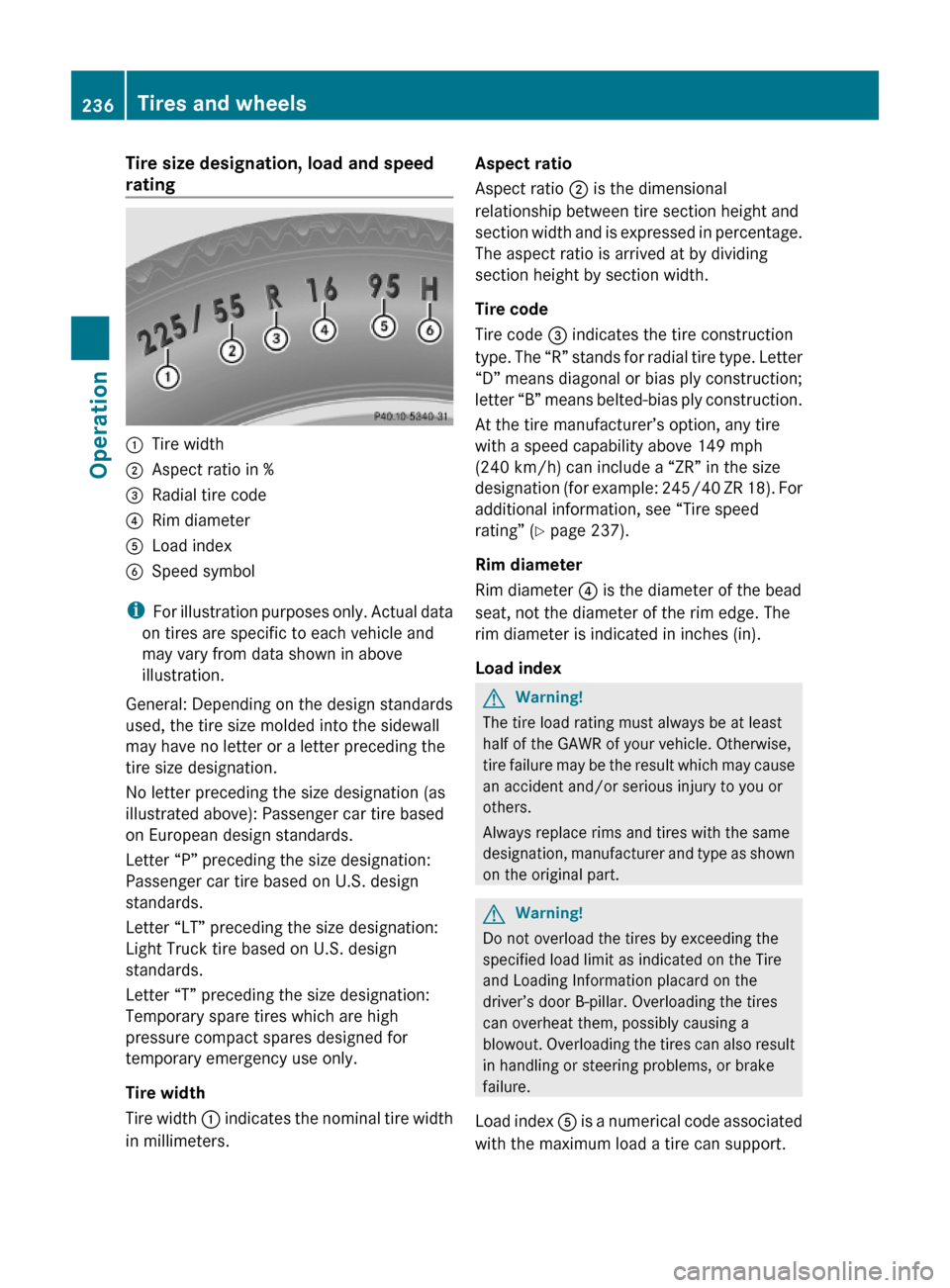
rating:Tire width;Aspect ratio in %=Radial tire code?Rim diameterALoad index BSpeed symbol
iFor illustration purposes only. Actual data
on tires are specific to each vehicle and
may vary from data shown in above
illustration.
General: Depending on the design standards
used, the tire size molded into the sidewall
may have no letter or a letter preceding the
tire size designation.
No letter preceding the size designation (as
illustrated above): Passenger car tire based
on European design standards.
Letter “P” preceding the size designation:
Passenger car tire based on U.S. design
standards.
Letter “LT” preceding the size designation:
Light Truck tire based on U.S. design
standards.
Letter “T” preceding the size designation:
Temporary spare tires which are high
pressure compact spares designed for
temporary emergency use only.
Tire width
Tire width : indicates the nominal tire width
in millimeters.
Aspect ratio
Aspect ratio ; is the dimensional
relationship between tire section height and
section width and is expressed in percentage.
The aspect ratio is arrived at by dividing
section height by section width.
Tire code
Tire code = indicates the tire construction
type. The “R” stands for radial tire type. Letter
“D” means diagonal or bias ply construction;
letter “B” means belted-bias ply construction.
At the tire manufacturer’s option, any tire
with a speed capability above 149 mph
(240 km/h) can include a “ZR” in the size
designation (for example: 245/40 ZR 18). For
additional information, see “Tire speed
rating” (Y page 237).
Rim diameter
Rim diameter ? is the diameter of the bead
seat, not the diameter of the rim edge. The
rim diameter is indicated in inches (in).
Load index
GWarning!
The tire load rating must always be at least
half of the GAWR of your vehicle. Otherwise,
tire failure may be the result which may cause
an accident and/or serious injury to you or
others.
Always replace rims and tires with the same
designation, manufacturer and type as shown
on the original part.
GWarning!
Do not overload the tires by exceeding the
specified load limit as indicated on the Tire
and Loading Information placard on the
driver’s door B-pillar. Overloading the tires
can overheat them, possibly causing a
blowout. Overloading the tires can also result
in handling or steering problems, or brake
failure.
Load index A is a numerical code associated
with the maximum load a tire can support.
236Tires and wheelsOperation
164_AKB; 7; 31, en-USd2ureepe,Version: 2.11.8.12009-09-11T12:07:36+02:00 - Seite 236
Page 243 of 368
Maximum loaded vehicle weight
The sum of curb weight, accessory weight,
total load limit, and production options
weight.
Maximum permissible tire inflation
pressure
This number is the greatest amount of air
pressure that should ever be put in the tire.
Normal occupant weight
The number of occupants the vehicle is
designed to seat, multiplied by 68 kilograms
(150 lb).
Occupant distribution
The distribution of occupants in a vehicle at
their designated seating positions.
Production options weight
The combined weight of those installed
regular production options weighing over
5 lbs (2.3 kilograms) in excess of those
standard items which they replace, not
previously considered in curb weight or
accessory weight, including heavy duty
brakes, ride levelers, roof rack, heavy duty
battery, and special trim.
PSI (Pounds per square inch)
A standard unit of measure for air pressure.
Recommended tire inflation pressure
The recommended tire inflation pressure for
normal driving conditions is listed on the Tire
and Loading Information placard located on
the driver’s door B-pillar. It provides best
handling, tread life and riding comfort.
Supplemental information pertaining to
special driving situations can be found on the
tire inflation pressure label on the inside of
the fuel filler flap.
Rim
A metal support for a tire or a tire and tube
assembly upon which the tire beads are
seated.
Sidewall
The portion of a tire between the tread and
the bead.
TIN (Tire Identification Number)
Unique identifier which facilitates efforts by
tire manufacturers to notify purchasers in
recall situations or other safety matters
concerning tires and gives purchasers the
means to easily identify such tires. The TIN is
comprised of “Manufacturer’s identification
mark”, “Tire size”, “Tire type code” and “Date
of manufacture”.
Tire ply composition and material used
This indicates the number of plies or the
number of layers of rubber-coated fabric in
the tire tread and sidewall. Tire
manufacturers also must indicate the ply
materials in the tire and sidewall, which
include steel, nylon, polyester, and others.
Tire speed rating
Part of tire designation (speed symbol);
indicates the speed range for which a tire is
approved.
Total load limit
Rated cargo and luggage load plus
68 kilograms (150 lb) times the vehicle’s
designated seating capacity.
Traction
The adhesive friction of a tire on a surface on
which it moves. The amount of grip provided.
Tires and wheels241Operation164_AKB; 7; 31, en-USd2ureepe,Version: 2.11.8.12009-09-11T12:07:36+02:00 - Seite 241Z