navigation MERCEDES-BENZ ML430 1997 Complete User Guide
[x] Cancel search | Manufacturer: MERCEDES-BENZ, Model Year: 1997, Model line: ML430, Model: MERCEDES-BENZ ML430 1997Pages: 4133, PDF Size: 88.89 MB
Page 1117 of 4133
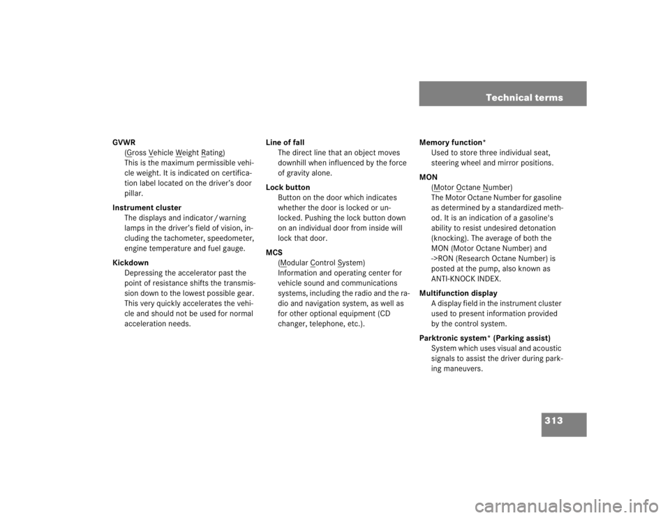
313 Technical terms
GVWR
(G
ross V
ehicle W
eight R
ating)
This is the maximum permissible vehi-
cle weight. It is indicated on certifica-
tion label located on the driver’s door
pillar.
Instrument cluster
The displays and indicator / warning
lamps in the driver’s field of vision, in-
cluding the tachometer, speedometer,
engine temperature and fuel gauge.
Kickdown
Depressing the accelerator past the
point of resistance shifts the transmis-
sion down to the lowest possible gear.
This very quickly accelerates the vehi-
cle and should not be used for normal
acceleration needs.Line of fall
The direct line that an object moves
downhill when influenced by the force
of gravity alone.
Lock button
Button on the door which indicates
whether the door is locked or un-
locked. Pushing the lock button down
on an individual door from inside will
lock that door.
MCS
(M
odular C
ontrol S
ystem)
Information and operating center for
vehicle sound and communications
systems, including the radio and the ra-
dio and navigation system, as well as
for other optional equipment (CD
changer, telephone, etc.).Memory function*
Used to store three individual seat,
steering wheel and mirror positions.
MON
(M
otor O
ctane N
umber)
The Motor Octane Number for gasoline
as determined by a standardized meth-
od. It is an indication of a gasoline's
ability to resist undesired detonation
(knocking). The average of both the
MON (Motor Octane Number) and
->RON (Research Octane Number) is
posted at the pump, also known as
ANTI-KNOCK INDEX.
Multifunction display
A display field in the instrument cluster
used to present information provided
by the control system.
Parktronic system* (Parking assist)
System which uses visual and acoustic
signals to assist the driver during park-
ing maneuvers.
Page 1496 of 4133
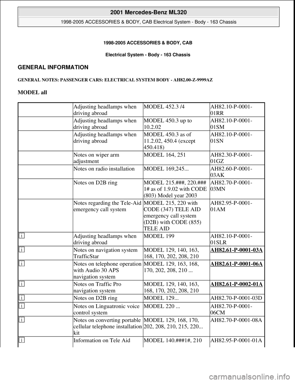
1998-2005 ACCESSORIES & BODY, CAB
Electrical System - Body - 163 Chassis
GENERAL INFORMATION
GENERAL NOTES: PASSENGER CARS: ELECTRICAL SYSTEM BODY - AH82.00-Z-9999AZ
MODEL all
Adjusting headlamps when
driving abroadMODEL 452.3 /4AH82.10-P-0001-
01RR
Adjusting headlamps when
driving abroadMODEL 450.3 up to
10.2.02AH82.10-P-0001-
01SM
Adjusting headlamps when
driving abroadMODEL 450.3 as of
11.2.02, 450.4 (except
450.418)AH82.10-P-0001-
01SN
Notes on wiper arm
adjustmentMODEL 164, 251AH82.30-P-0001-
01GZ
Notes on radio installationMODEL 169,245...AH82.60-P-0001-
03AK
Notes on D2B ringMODEL 215.###, 220.###
1# as of 1.9.02 with CODE
(803) Model year 2003AH82.70-P-0001-
03MN
Notes regarding the Tele-Aid
emergency call systemMODEL 215, 220 with
CODE (347) TELE AID
emergency call system
(D2B) with CODE (855)
TELE AIDAH82.95-P-0001-
01AM
Adjusting headlamps when
driving abroadMODEL 199AH82.10-P-0001-
01SLR
Notes on navigation system
TrafficStarMODEL 129, 140, 163,
168, 170, 202, 208, 210AH82.61-P-0001-03A
Notes on telephone operation
with Audio 30 APS
navigation systemMODEL 129, 163, 168,
170, 202, 208, 210 ...AH82.61-P-0001-06A
Notes on Traffic Pro
navigation systemMODEL 129, 140, 163,
168, 170, 202, 208, 210AH82.61-P-0002-01A
Notes on D2B ringMODEL 129...AH82.70-P-0001-03D
Notes on Linguatronic voice
control systemMODEL 220 ...AH82.70-P-0001-
06CM
Notes on converting portable
cellular telephone installation
kitMODEL 129, 168, 170,
202, 208, 210, 215, 220...AH82.70-P-0001-08A
Information on Tele Aid MODEL 140.###1#, 210 AH82.95-P-0001-01A
2001 Mercedes-Benz ML320
1998-2005 ACCESSORIES & BODY, CAB Electrical System - Body - 163 Chassis
2001 Mercedes-Benz ML320
1998-2005 ACCESSORIES & BODY, CAB Electrical System - Body - 163 Chassis
me
Saturday, October 02, 2010 3:30:03 PMPage 1 © 2006 Mitchell Repair Information Company, LLC.
me
Saturday, October 02, 2010 3:30:18 PMPage 1 © 2006 Mitchell Repair Information Company, LLC.
Page 1498 of 4133
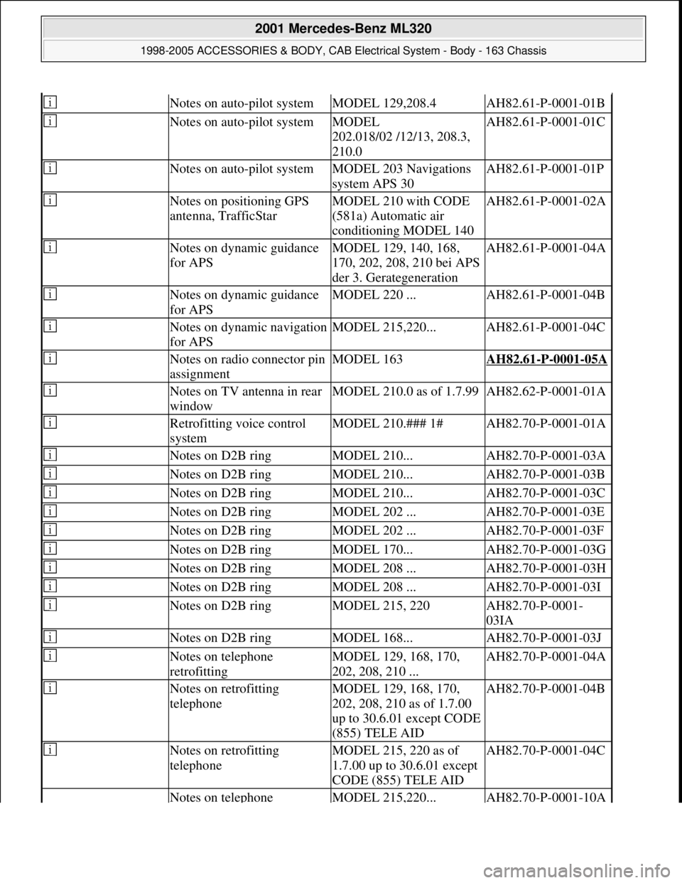
Notes on auto-pilot systemMODEL 129,208.4AH82.61-P-0001-01B
Notes on auto-pilot systemMODEL
202.018/02 /12/13, 208.3,
210.0AH82.61-P-0001-01C
Notes on auto-pilot systemMODEL 203 Navigations
system APS 30AH82.61-P-0001-01P
Notes on positioning GPS
antenna, TrafficStarMODEL 210 with CODE
(581a) Automatic air
conditioning MODEL 140AH82.61-P-0001-02A
Notes on dynamic guidance
for APSMODEL 129, 140, 168,
170, 202, 208, 210 bei APS
der 3. GerategenerationAH82.61-P-0001-04A
Notes on dynamic guidance
for APSMODEL 220 ...AH82.61-P-0001-04B
Notes on dynamic navigation
for APSMODEL 215,220...AH82.61-P-0001-04C
Notes on radio connector pin
assignmentMODEL 163AH82.61-P-0001-05A
Notes on TV antenna in rear
windowMODEL 210.0 as of 1.7.99AH82.62-P-0001-01A
Retrofitting voice control
systemMODEL 210.### 1#AH82.70-P-0001-01A
Notes on D2B ringMODEL 210...AH82.70-P-0001-03A
Notes on D2B ringMODEL 210...AH82.70-P-0001-03B
Notes on D2B ringMODEL 210...AH82.70-P-0001-03C
Notes on D2B ringMODEL 202 ...AH82.70-P-0001-03E
Notes on D2B ringMODEL 202 ...AH82.70-P-0001-03F
Notes on D2B ringMODEL 170...AH82.70-P-0001-03G
Notes on D2B ringMODEL 208 ...AH82.70-P-0001-03H
Notes on D2B ringMODEL 208 ...AH82.70-P-0001-03I
Notes on D2B ringMODEL 215, 220AH82.70-P-0001-
03IA
Notes on D2B ringMODEL 168...AH82.70-P-0001-03J
Notes on telephone
retrofittingMODEL 129, 168, 170,
202, 208, 210 ...AH82.70-P-0001-04A
Notes on retrofitting
telephoneMODEL 129, 168, 170,
202, 208, 210 as of 1.7.00
up to 30.6.01 except CODE
(855) TELE AIDAH82.70-P-0001-04B
Notes on retrofitting
telephoneMODEL 215, 220 as of
1.7.00 up to 30.6.01 except
CODE (855) TELE AIDAH82.70-P-0001-04C
Notes on telephone MODEL 215,220...AH82.70-P-0001-10A
2001 Mercedes-Benz ML320
1998-2005 ACCESSORIES & BODY, CAB Electrical System - Body - 163 Chassis
me
Saturday, October 02, 2010 3:30:04 PMPage 3 © 2006 Mitchell Repair Information Company, LLC.
Page 1499 of 4133
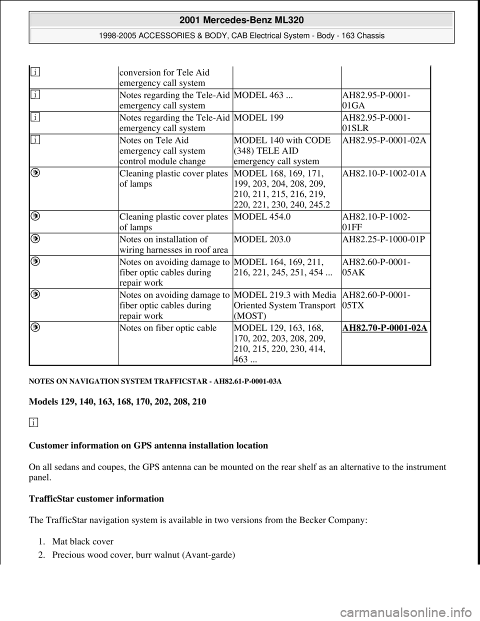
NOTES ON NAVIGATION SYSTEM TRAFFICSTAR - AH82.61-P-0001-03A
Models 129, 140, 163, 168, 170, 202, 208, 210
Customer information on GPS antenna installation location
On all sedans and coupes, the GPS antenna can be mounted on the rear shelf as an alternative to the instrument
panel.
TrafficStar customer information
The TrafficStar navigation system is available in two versions from the Becker Company:
1. Mat black cover
2. Precious wood cover, burr walnut (Avant-
garde)
conversion for Tele Aid
emergency call system
Notes regarding the Tele-Aid
emergency call systemMODEL 463 ...AH82.95-P-0001-
01GA
Notes regarding the Tele-Aid
emergency call systemMODEL 199AH82.95-P-0001-
01SLR
Notes on Tele Aid
emergency call system
control module changeMODEL 140 with CODE
(348) TELE AID
emergency call systemAH82.95-P-0001-02A
Cleaning plastic cover plates
of lampsMODEL 168, 169, 171,
199, 203, 204, 208, 209,
210, 211, 215, 216, 219,
220, 221, 230, 240, 245.2AH82.10-P-1002-01A
Cleaning plastic cover plates
of lampsMODEL 454.0AH82.10-P-1002-
01FF
Notes on installation of
wiring harnesses in roof areaMODEL 203.0AH82.25-P-1000-01P
Notes on avoiding damage to
fiber optic cables during
repair workMODEL 164, 169, 211,
216, 221, 245, 251, 454 ...AH82.60-P-0001-
05AK
Notes on avoiding damage to
fiber optic cables during
repair workMODEL 219.3 with Media
Oriented System Transport
(MOST)AH82.60-P-0001-
05TX
Notes on fiber optic cableMODEL 129, 163, 168,
170, 202, 203, 208, 209,
210, 215, 220, 230, 414,
463 ...AH82.70-P-0001-02A
2001 Mercedes-Benz ML320
1998-2005 ACCESSORIES & BODY, CAB Electrical System - Body - 163 Chassis
me
Saturday, October 02, 2010 3:30:04 PMPage 4 © 2006 Mitchell Repair Information Company, LLC.
Page 1500 of 4133
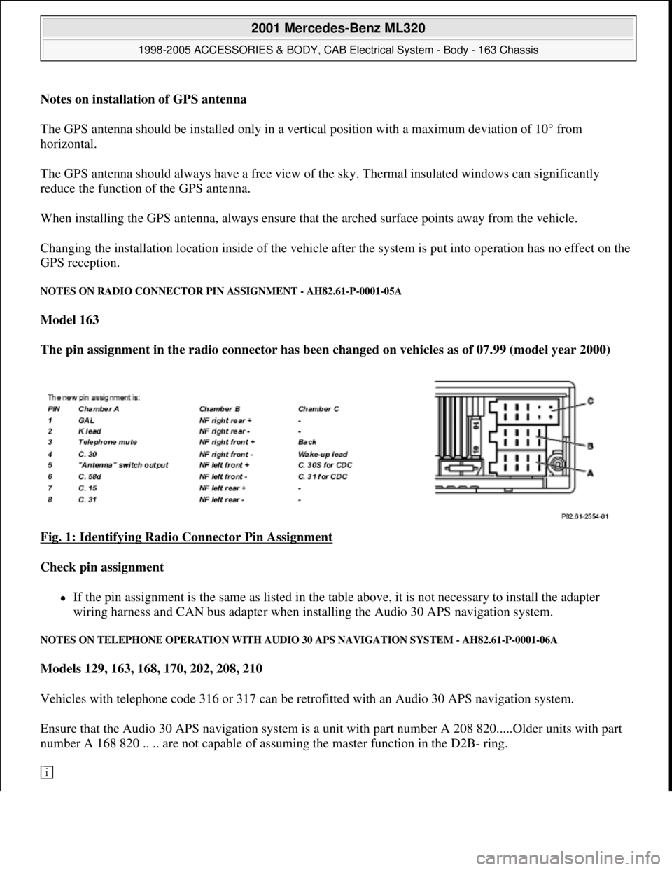
Notes on installation of GPS antenna
The GPS antenna should be installed only in a vertical position with a maximum deviation of 10° from
horizontal.
The GPS antenna should always have a free view of the sky. Thermal insulated windows can significantly
reduce the function of the GPS antenna.
When installing the GPS antenna, always ensure that the arched surface points away from the vehicle.
Changing the installation location inside of the vehicle after the system is put into operation has no effect on the
GPS reception.
NOTES ON RADIO CONNECTOR PIN ASSIGNMENT - AH82.61-P-0001-05A
Model 163
The pin assignment in the radio connector has been changed on vehicles as of 07.99 (model year 2000)
Fig. 1: Identifying Radio Connector Pin Assignment
Check pin assignment
If the pin assignment is the same as listed in the table above, it is not necessary to install the adapter
wiring harness and CAN bus adapter when installing the Audio 30 APS navigation system.
NOTES ON TELEPHONE OPERATION WITH AUDIO 30 APS NAVIGATION SYSTEM - AH82.61-P-0001-06A
Models 129, 163, 168, 170, 202, 208, 210
Vehicles with telephone code 316 or 317 can be retrofitted with an Audio 30 APS navigation system.
Ensure that the Audio 30 APS navigation system is a unit with part number A 208 820.....Older units with part
number A 168 820 .. .. are not capable of assuming the master function in the D2B- ring.
2001 Mercedes-Benz ML320
1998-2005 ACCESSORIES & BODY, CAB Electrical System - Body - 163 Chassis
me
Saturday, October 02, 2010 3:30:04 PMPage 5 © 2006 Mitchell Repair Information Company, LLC.
Page 1501 of 4133
The Audio 30 APS does not have a number pad. For this reason, it is not possible to control the telephone over
the radio (see operating instructions).
On vehicles (as of approx. 07.99) with multifunction steering wheel (telephone control with keys on steering
wheel) this function is then also possible with the Audio 30 APS navigation system.
NOTES ON TRAFFIC PRO NAVIGATION SYSTEM - AH82.61-P-0002-01A
Models 129, 140, 163, 168, 170, 202, 208, 210
Customer information, installation position for GPS antenna
There are two different installation locations for the GSP antenna:
1. Standard GPS antenna from DaimlerChrysler on roof or trunk lid. This version offers the best reception
and is therefore preferable.
2. Use of magnetic antenna in vehicle passenger compartment. This version is part of the kit from the
Becker company and installation is described in Becker installation instructions.
Notes on installation of Becker GPS antenna
The GPS antenna can only be installed horizontally with a maximum deviation of 10° from horizontal.
The GPS antenna should always have an unobstructed view of the sky. Tinted windows can reduce the function
of the GPS antenna considerably.
When installing the GPS antenna always ensure that the arched surface of the antenna points upwards.
NOTES ON FIBER OPTIC CABLE - AH82.70-P-0001-02A
Model 129, 163, 168, 170, 202, 203, 208, 209, 210, 215, 220, 230, 414,
463.243/244/245/246/247/248/249/250/254/270/271/303/309/322/323/332/333/340/341
Illustrated on Model 202 sedan
2001 Mercedes-Benz ML320
1998-2005 ACCESSORIES & BODY, CAB Electrical System - Body - 163 Chassis
me
Saturday, October 02, 2010 3:30:04 PMPage 6 © 2006 Mitchell Repair Information Company, LLC.
Page 1553 of 4133
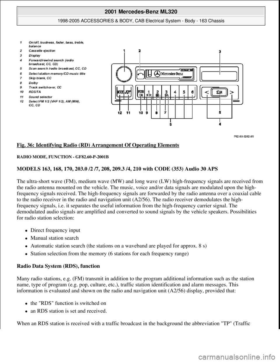
Fig. 36: Identifying Radio (RD) Arrangement Of Operating Elements
RADIO MODE, FUNCTION - GF82.60-P-2001B
MODELS 163, 168, 170, 203.0 /2 /7, 208, 209.3 /4, 210 with CODE (353) Audio 30 APS
The ultra-short wave (FM), medium wave (MW) and long wave (LW) high-frequency signals are received from
the radio antenna mounted on the vehicle. The music, voice and/or data signals are modulated upon the high-
frequency signals received. The high-frequency signals are forwarded by the radio antenna over a coaxial cable
to the radio receiver in the radio and navigation unit (A2/56). The radio receiver demodulates the high-
frequency signals, i.e. it separates the useful information from the high-frequency carrier signal. The
demodulated audio signals are amplified and converted to sound signals by the vehicle speakers. Possibilities
for radio station selection:
Direct frequency input
Manual station search
Automatic station search (the stations on a waveband are played for approx. 8 s)
Station selection from the memory (6 stations for each frequency range)
Radio Data System (RDS), function
Many radio stations, e.g. (FM) transmit in addition to the program additional information such as the station
name, type of program (e.g. pop, culture, etc.), traffic station identification and alarm messages. This
information is evaluated and shown on the radio and navigation unit (A2/56) display, provided that:
the "RDS" function is switched on
an RDS station is set and received.
When an RDS station is received with a traffic broadcast in the background the abbreviation "TP" (Traffic
2001 Mercedes-Benz ML320
1998-2005 ACCESSORIES & BODY, CAB Electrical System - Body - 163 Chassis
me
Saturday, October 02, 2010 3:30:05 PMPage 58 © 2006 Mitchell Repair Information Company, LLC.
Page 1554 of 4133
Program) appears on the radio and navigation unit display (A2/56).
Even when the RDS function is deactivated, the traffic station recognition and station following function remain
in operation (if activated). RDS alarm messages are still issued. In this case, CD playback or radio reception is
automatically interrupted.
2-tuner technology function
If interference occurs to reception while driving, the system attempts to receive the selected station on an
alternative frequency with the aid of the second (integrated) receiver and switch over when reception is better.
Moreover, the second radio receiver automatically generates a list of the receivable FM stations after switch-on,
and this list is continuously updated during operation. The stations contained in the list can be called up sorted
in alphabetical order with the station search buttons.
The station list is only available when the "RDS" function is activated.
At certain times, some radio channel programs are subdivided into regional programs.
Since the system automatically switches to an alternative frequency in the event of reception interference, this
can lead to a change in the regional program (not the radio network). If this is not desired, the regional program
function can be activated in the menu "REG". Switchover to an alternative frequency is then accomplished only
within the regional program.
FM antenna diversity function (models 209.3/4)
The antenna diversity function undertakes a reception-specific switchover between the FM antennas on the rear
window for model 209.3 (FM antennas of windshield for model 209.4). The function runs automatically and is
executed by the window antenna amplifier module 1 (A2/71) for model 209.3 (left antenna amplifier module
(A2/64) for model 209.4).
The radio tuner of the radio and navigation unit (A2/56) only generates the intermediate frequency (ZF) signal,
which serves as a reference to change the FM antenna for the window antenna amplifier module 1 (A2/71) on
model 209.3 (for model 209.4 left antenna amplifier module (A2/64)).
RDS Diversity/2-receiver technology function
The system consists of 2 FM receivers, a radio receiver and a search receiver. After turning on the radio system,
the search receiver automatically generates a list of FM stations received, which is continually updated during
operation.
Data such as reception quality, programs and alternative frequencies are stored. The audio receiver can therefore
switch over inaudibly to an alternative frequency. The list appears in alphabetical order when the "FM station
list" is called up. The stations which are displayed can be activated by selecting and confirming.
FM/AM antenna amplifier,
location/task/design/ functionModels 163, 168,
170, 208.4, 210.2
Models 208.3, 210 GF82.62-P-4101A
2001 Mercedes-Benz ML320
1998-2005 ACCESSORIES & BODY, CAB Electrical System - Body - 163 Chassis
me
Saturday, October 02, 2010 3:30:05 PMPage 59 © 2006 Mitchell Repair Information Company, LLC.
Page 1555 of 4133
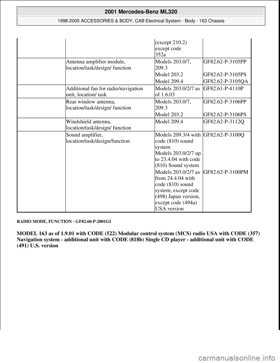
RADIO MODE, FUNCTION - GF82.60-P-2001GI
MODEL 163 as of 1.9.01 with CODE (522) Modular control system (MCS) radio USA with CODE (357)
Navigation system - additional unit with CODE (818b) Single CD player - additional unit with CODE
(491) U.S. version
(except 210.2)
except code
352a
Antenna amplifier module,
location/task/design/ functionModels 203.0/7,
209.3GF82.62-P-3105PP
Model 203.2GF82.62-P-3105PS
Model 209.4GF82.62-P-3105QA
Additional fan for radio/navigation
unit, location/ taskModels 203.0/2/7 as
of 1.6.03GF82.61-P-4110P
Rear window antenna,
location/task/design/ functionModels 203.0/7,
209.3GF82.62-P-3106PP
Model 203.2GF82.62-P-3106PS
Windshield antenna,
location/task/design/ functionModel 209.4GF82.62-P-3112Q
Sound amplifier,
location/task/design/functionModels 209.3/4 with
code (810) sound
system
Models 203.0/2/7 up
to 23.4.04 with code
(810) Sound systemGF82.62-P-3100Q
Models 203.0/2/7 as
from 24.4.04 with
code (810) sound
system, except code
(498) Japan version,
except code (494a)
USA versionGF82.62-P-3100PM
2001 Mercedes-Benz ML320
1998-2005 ACCESSORIES & BODY, CAB Electrical System - Body - 163 Chassis
me
Saturday, October 02, 2010 3:30:05 PMPage 60 © 2006 Mitchell Repair Information Company, LLC.
Page 1556 of 4133
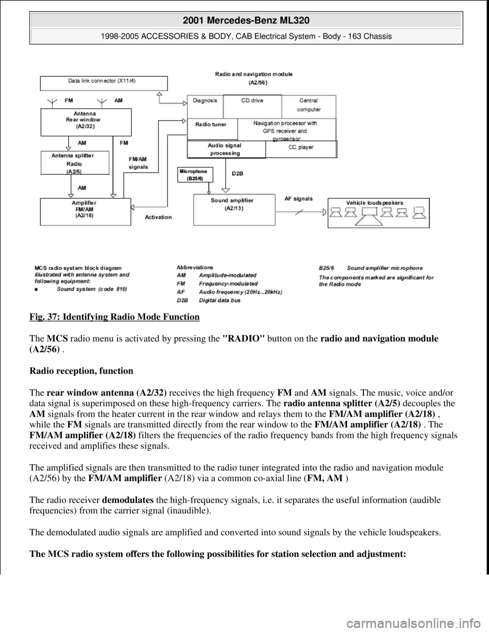
Fig. 37: Identifying Radio Mode Function
The MCS radio menu is activated by pressing the "RADIO" button on the radio and navigation module
(A2/56) .
Radio reception, function
The rear window antenna (A2/32) receives the high frequency FM and AM signals. The music, voice and/or
data signal is superimposed on these high-frequency carriers. The radio antenna splitter (A2/5) decouples the
AM signals from the heater current in the rear window and relays them to the FM/AM amplifier (A2/18) ,
while the FM signals are transmitted directly from the rear window to the FM/AM amplifier (A2/18) . The
FM/AM amplifier (A2/18) filters the frequencies of the radio frequency bands from the high frequency signals
received and amplifies these signals.
The amplified signals are then transmitted to the radio tuner integrated into the radio and navigation module
(A2/56) by the FM/AM amplifier (A2/18) via a common co-axial line (FM, AM )
The radio receiver demodulates the high-frequency signals, i.e. it separates the useful information (audible
frequencies) from the carrier signal (inaudible).
The demodulated audio signals are amplified and converted into sound signals by the vehicle loudspeakers.
The MCS radio system offers the following possibilities for station selection and adjustment:
2001 Mercedes-Benz ML320
1998-2005 ACCESSORIES & BODY, CAB Electrical System - Body - 163 Chassis
me
Saturday, October 02, 2010 3:30:05 PMPage 61 © 2006 Mitchell Repair Information Company, LLC.