MERCEDES-BENZ ML430 1997 Complete Repair Manual
Manufacturer: MERCEDES-BENZ, Model Year: 1997, Model line: ML430, Model: MERCEDES-BENZ ML430 1997Pages: 4133, PDF Size: 88.89 MB
Page 2411 of 4133
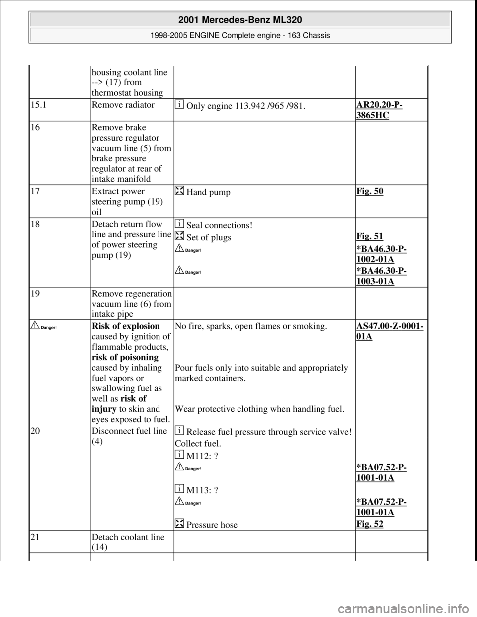
housing coolant line
--> (17) from
thermostat housing
15.1Remove radiator Only engine 113.942 /965 /981.AR20.20-P-
3865HC
16Remove brake
pressure regulator
vacuum line (5) from
brake pressure
regulator at rear of
intake manifold
17Extract power
steering pump (19)
oil Hand pumpFig. 50
18Detach return flow
line and pressure line
of power steering
pump (19) Seal connections!
Set of plugsFig. 51
*BA46.30-P-
1002-01A
*BA46.30-P-
1003-01A
19Remove regeneration
vacuum line (6) from
intake pipe
Risk of explosion
caused by ignition of
flammable products,
risk of poisoning
caused by inhaling
fuel vapors or
swallowing fuel as
well as risk of
injury to skin and
eyes exposed to fuel.No fire, sparks, ope n flames or smoking.AS47.00-Z-0001-
01A
Pour fuels only into suitable and appropriately
marked containers.
Wear protective clothing when handling fuel.
20Disconnect fuel line
(4) Release fuel pressure through service valve!
Collect fuel.
M112: ?
*BA07.52-P-
1001-01A
M113: ?
*BA07.52-P-
1001-01A
Pressure hoseFig. 52
21Detach coolant line
(14)
2001 Mercedes-Benz ML320
1998-2005 ENGINE Complete engine - 163 Chassis
me
Saturday, October 02, 2010 3:17:56 PMPage 55 © 2006 Mitchell Repair Information Company, LLC.
Page 2412 of 4133
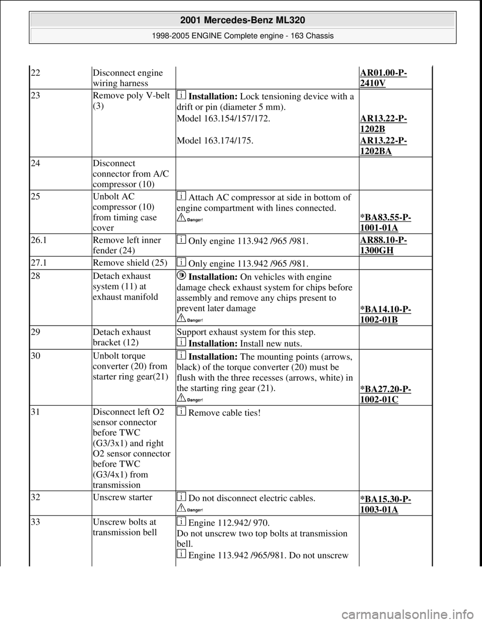
22Disconnect engine
wiring harness AR01.00-P-
2410V
23Remove poly V-belt
(3) Installation: Lock tensioning device with a
drift or pin (diameter 5 mm).
Model 163.154/157/172.AR13.22-P-
1202B
Model 163.174/175.AR13.22-P-
1202BA
24Disconnect
connector from A/C
compressor (10)
25Unbolt AC
compressor (10)
from timing case
cover Attach AC compressor at side in bottom of
engine compartment with lines connected.
*BA83.55-P-
1001-01A
26.1Remove left inner
fender (24) Only engine 113.942 /965 /981.AR88.10-P-
1300GH
27.1Remove shield (25) Only engine 113.942 /965 /981.
28Detach exhaust
system (11) at
exhaust manifold Installation: On vehicles with engine
damage check exhaust sy stem for chips before
assembly and remove any chips present to
prevent later damage
*BA14.10-P-
1002-01B
29Detach exhaust
bracket (12)Support exhaust system for this step.
Installation: Install new nuts.
30Unbolt torque
converter (20) from
starter ring gear(21) Installation: The mounting points (arrows,
black) of the torque converter (20) must be
flush with the three recesses (arrows, white) in
the starting ring gear (21).
*BA27.20-P-
1002-01C
31Disconnect left O2
sensor connector
before TWC
(G3/3x1) and right
O2 sensor connector
before TWC
(G3/4x1) from
transmission Remove cable ties!
32Unscrew starter Do not disconnect electric cables.
*BA15.30-P-
1003-01A
33Unscrew bolts at
transmission bell Engine 112.942/ 970.
Do not unscrew two top bolts at transmission
bell.
Engine 113.942 /965/ 981. Do not unscrew
2001 Mercedes-Benz ML320
1998-2005 ENGINE Complete engine - 163 Chassis
me
Saturday, October 02, 2010 3:17:56 PMPage 56 © 2006 Mitchell Repair Information Company, LLC.
Page 2413 of 4133
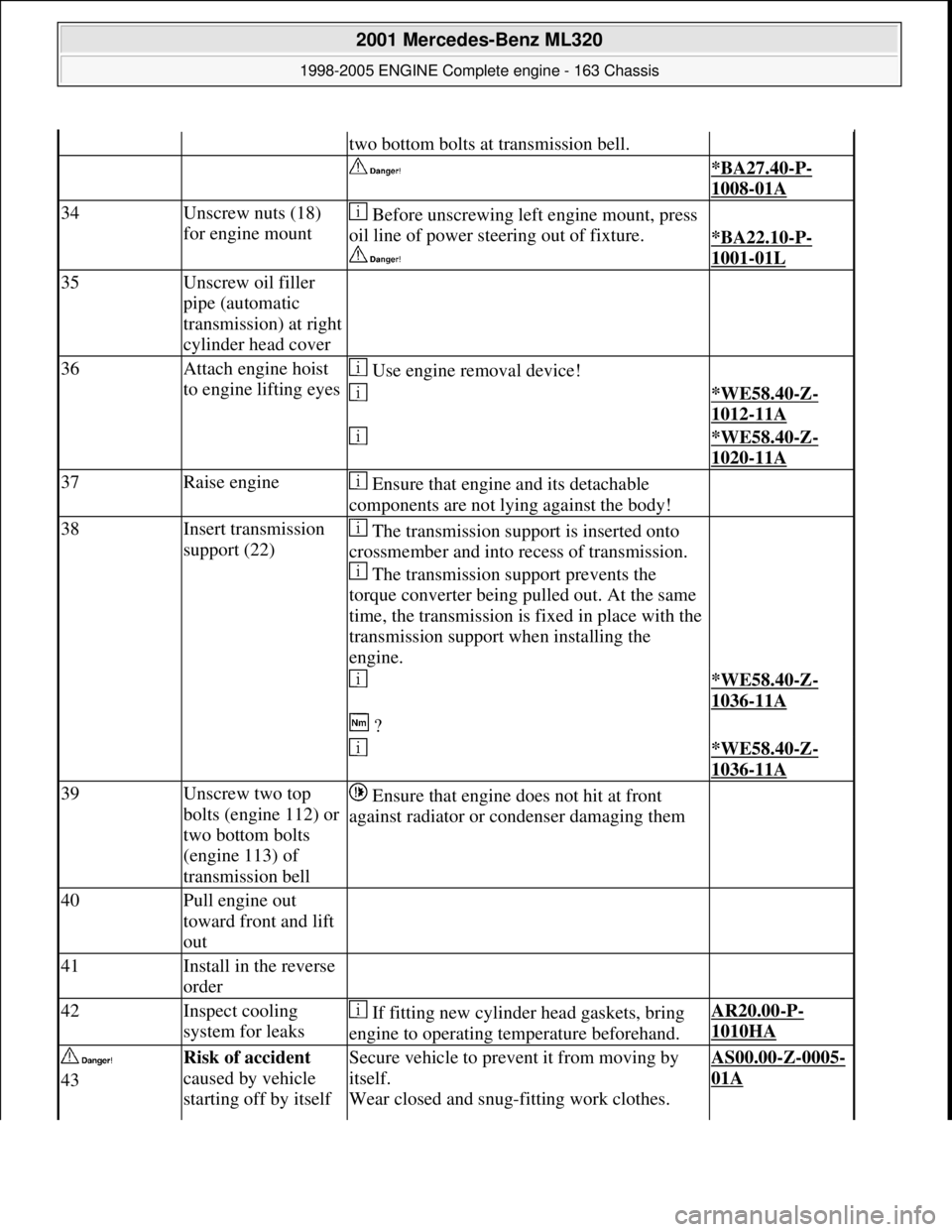
two bottom bolts at transmission bell.
*BA27.40-P-
1008-01A
34Unscrew nuts (18)
for engine mount Before unscrewing left engine mount, press
oil line of power stee ring out of fixture.
*BA22.10-P-
1001-01L
35Unscrew oil filler
pipe (automatic
transmission) at right
cylinder head cover
36Attach engine hoist
to engine lifting eyes Use engine removal device!
*WE58.40-Z-
1012-11A
*WE58.40-Z-
1020-11A
37Raise engine Ensure that engine and its detachable
components are not lying against the body!
38Insert transmission
support (22) The transmission support is inserted onto
crossmember and into recess of transmission.
The transmission support prevents the
torque converter being pulled out. At the same
time, the transmission is fixed in place with the
transmission support when installing the
engine.
*WE58.40-Z-
1036-11A
?
*WE58.40-Z-
1036-11A
39Unscrew two top
bolts (engine 112) or
two bottom bolts
(engine 113) of
transmission bell Ensure that engine does not hit at front
against radiator or condenser damaging them
40Pull engine out
toward front and lift
out
41Install in the reverse
order
42Inspect cooling
system for leaks If fitting new cylinder head gaskets, bring
engine to operating temperature beforehand.AR20.00-P-
1010HA
43Risk of accident
caused by vehicle
starting off by itself Secure vehicle to prev ent it from moving by
itself.
Wear closed and snug-fitting work clothes. AS00.00-Z-0005-
01A
2001 Mercedes-Benz ML320
1998-2005 ENGINE Complete engine - 163 Chassis
me
Saturday, October 02, 2010 3:17:56 PMPage 57 © 2006 Mitchell Repair Information Company, LLC.
Page 2414 of 4133
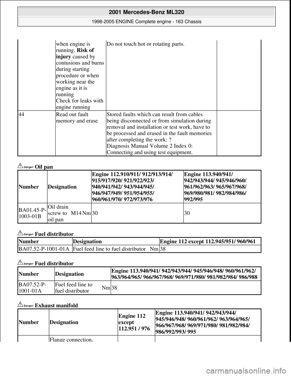
Oil pan
Fuel distributor
Fuel distributor
Exhaust manifold
when engine is
running. Risk of
injury caused by
contusions and burns
during starting
procedure or when
working near the
engine as it is
running
Check for leaks with
engine runningDo not touch hot or rotating parts.
44Read out fault
memory and eraseStored faults which can result from cables
being disconnected or from simulation during
removal and installation or test work, have to
be processed and erased in the fault memories
after completing the work: ?
Diagnosis Manual Volume 2 Index 0:
Connecting and using test equipment.
NumberDesignation
Engine 112.910/911/ 912/913/914/
915/917/920/ 921/922/923/
940/941/942/ 943/944/945/
946/947/949/ 951/954/955/
960/961/970/ 972/973/976Engine 113.940/941/
942/943/944/ 945/946/960/
961/962/963/ 965/967/968/
969/980/981/ 982/984/986/
992/995
BA01.45-P-
1003-01BOil drain
screw to
oil pan
M14Nm3030
NumberDesignationEngine 112 except 112.945/951/ 960/961
BA07.52-P-1001-01AFuel feed line to fuel distributorNm38
NumberDesignationEngine 113.940/941/ 942/943/944/ 945/946/948/ 960/961/962/
963/964/965/ 966/967/968/ 969/971/ 980/ 981/982/984/ 986/988
BA07.52-P-
1001-01AFuel feed line to
fuel distributorNm38
NumberDesignation
Engine 112
except
112.951 / 976Engine 113.940/941/ 942/943/944/
945/946/948/ 960/961/962/ 963/964/965/
966/967/968/ 969/971/980/ 981/982/984/
986/992/993/ 995
Flange connection,
2001 Mercedes-Benz ML320
1998-2005 ENGINE Complete engine - 163 Chassis
me
Saturday, October 02, 2010 3:17:56 PMPage 58 © 2006 Mitchell Repair Information Company, LLC.
Page 2415 of 4133
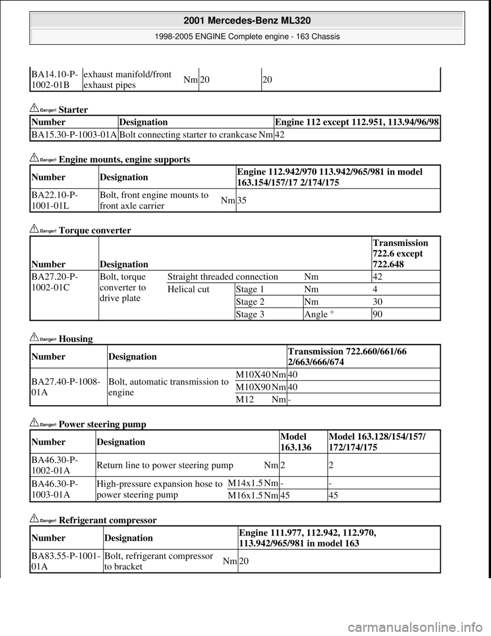
Starter
Engine mounts, engine supports
Torque converter
Housing
Power steering pump
Refrigerant compressor
BA14.10-P-
1002-01Bexhaust manifold/front
exhaust pipesNm2020
NumberDesignationEngine 112 except 112.951, 113.94/96/98
BA15.30-P-1003-01ABolt connecting starter to crankcaseNm42
NumberDesignationEngine 112.942/970 113.942/965/981 in model
163.154/157/17 2/174/175
BA22.10-P-
1001-01LBolt, front engine mounts to
front axle carrierNm35
NumberDesignation
Transmission
722.6 except
722.648
BA27.20-P-
1002-01CBolt, torque
converter to
drive plateStraight threaded connectionNm42
Helical cutStage 1Nm4
Stage 2Nm30
Stage 3Angle °90
NumberDesignationTransmission 722.660/661/66
2/663/666/674
BA27.40-P-1008-
01ABolt, automatic transmission to
engineM10X40Nm40
M10X90Nm40
M12Nm-
NumberDesignationModel
163.136Model 163.128/154/157/
172/174/175
BA46.30-P-
1002-01AReturn line to power steering pumpNm22
BA46.30-P-
1003-01AHigh-pressure expansion hose to
power steering pumpM14x1.5Nm--
M16x1.5Nm4545
NumberDesignationEngine 111.977, 112.942, 112.970,
113.942/965/981 in model 163
BA83.55-P-1001-
01ABolt, refrigerant compressor
to bracketNm20
2001 Mercedes-Benz ML320
1998-2005 ENGINE Complete engine - 163 Chassis
me
Saturday, October 02, 2010 3:17:56 PMPage 59 © 2006 Mitchell Repair Information Company, LLC.
Page 2416 of 4133
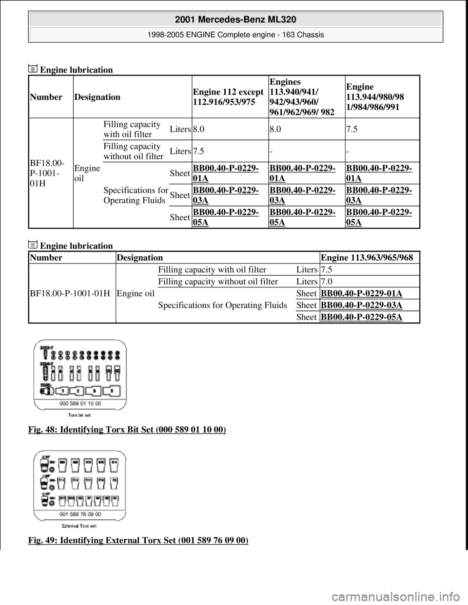
Engine lubrication
Engine lubrication
Fig. 48: Identifying Torx Bit Set (000 589 01 10 00)
Fig. 49: Identifying External Torx Set (001 589 76 09 00)
NumberDesignationEngine 112 except
112.916/953/975
Engines
113.940/941/
942/943/960/
961/962/969/ 982Engine
113.944/980/98
1/984/986/991
BF18.00-
P-1001-
01HEngine
oil
Filling capacity
with oil filterLiters8.08.07.5
Filling capacity
without oil filterLiters7.5--
Specifications for
Operating Fluids
SheetBB00.40-P-0229-
01A
BB00.40-P-0229-
01A
BB00.40-P-0229-
01A
SheetBB00.40-P-0229-
03A
BB00.40-P-0229-
03A
BB00.40-P-0229-
03A
SheetBB00.40-P-0229-
05A
BB00.40-P-0229-
05A
BB00.40-P-0229-
05A
NumberDesignationEngine 113.963/965/968
BF18.00-P-1001-01HEngine oil
Filling capacity with oil filterLiters7.5
Filling capacity without oil filterLiters7.0
Specifications for Operating Fluids
SheetBB00.40-P-0229-01A
SheetBB00.40-P-0229-03A
SheetBB00.40-P-0229-05A
2001 Mercedes-Benz ML320
1998-2005 ENGINE Complete engine - 163 Chassis
me
Saturday, October 02, 2010 3:17:56 PMPage 60 © 2006 Mitchell Repair Information Company, LLC.
Page 2417 of 4133
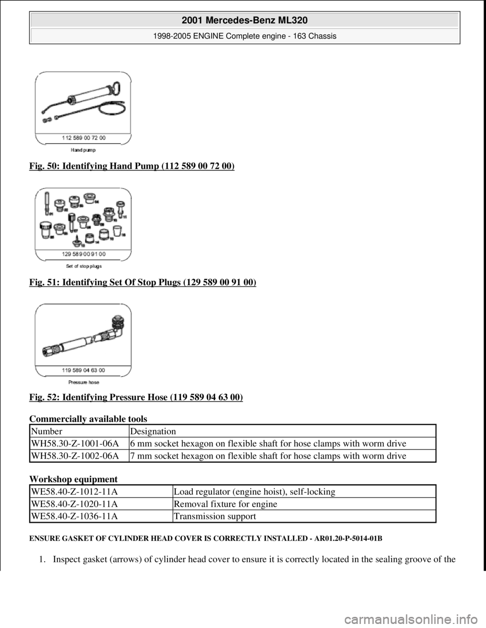
Fig. 50: Identifying Hand Pump (112 589 00 72 00)
Fig. 51: Identifying Set Of Stop Plugs (129 589 00 91 00)
Fig. 52: Identifying Pressure Hose (119 589 04 63 00)
Commercially available tools
Workshop equipment
ENSURE GASKET OF CYLINDER HEAD COVER IS CORRECTLY INSTALLED - AR01.20-P-5014-01B
1. Inspect gasket (arrows) of cylinder head cover to ensure it is correctly located in the sealing groove of the
NumberDesignation
WH58.30-Z-1001-06A6 mm socket hexagon on flexible shaft for hose clamps with worm drive
WH58.30-Z-1002-06A7 mm socket hexagon on flexible shaft for hose clamps with worm drive
WE58.40-Z-1012-11ALoad regulator (engine hoist), self-locking
WE58.40-Z-1020-11ARemoval fixture for engine
WE58.40-Z-1036-11ATransmission support
2001 Mercedes-Benz ML320
1998-2005 ENGINE Complete engine - 163 Chassis
me
Saturday, October 02, 2010 3:17:56 PMPage 61 © 2006 Mitchell Repair Information Company, LLC.
Page 2418 of 4133
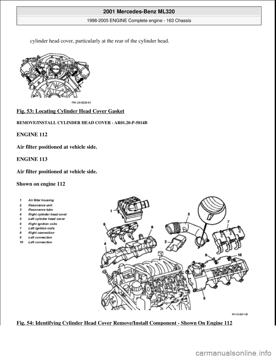
cylinder head cover, particularly at the rear of the cylinder head.
Fig. 53: Locating Cylinder Head Cover Gasket
REMOVE/INSTALL CY LINDER HEAD COVER - AR01.20-P-5014B
ENGINE 112
Air filter positioned at vehicle side.
ENGINE 113
Air filter positioned at vehicle side.
Shown on engine 112
Fig. 54: Identifying Cylinder Head Cover Remove/Install Component
- Shown On Engine 112
2001 Mercedes-Benz ML320
1998-2005 ENGINE Complete engine - 163 Chassis
me
Saturday, October 02, 2010 3:17:56 PMPage 62 © 2006 Mitchell Repair Information Company, LLC.
Page 2419 of 4133
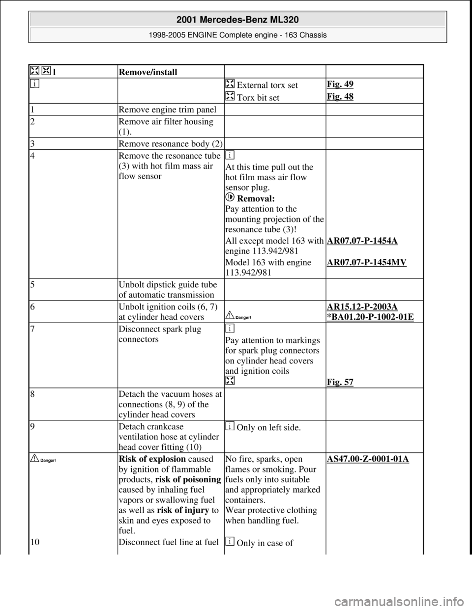
lRemove/install
External torx setFig. 49
Torx bit setFig. 48
1Remove engine trim panel
2Remove air filter housing
(1).
3Remove resonance body (2)
4Remove the resonance tube
(3) with hot film mass air
flow sensor
At this time pull out the
hot film mass air flow
sensor plug.
Removal:
Pay attention to the
mounting projection of the
resonance tube (3)!
All except model 163 with
engine 113.942/981AR07.07-P-1454A
Model 163 with engine
113.942/981AR07.07-P-1454MV
5Unbolt dipstick guide tube
of automatic transmission
6Unbolt ignition coils (6, 7)
at cylinder head covers
AR15.12-P-2003A
*BA01.20
-P-1002-01E
7Disconnect spark plug
connectors
Pay attention to markings
for spark plug connectors
on cylinder head covers
and ignition coils
Fig. 57
8Detach the vacuum hoses at
connections (8, 9) of the
cylinder head covers
9Detach crankcase
ventilation hose at cylinder
head cover fitting (10) Only on left side.
Risk of explosion caused
by ignition of flammable
products, risk of poisoning
caused by inhaling fuel
vapors or swallowing fuel
as well as risk of injury to
skin and eyes exposed to
fuel.No fire, sparks, open
flames or smoking. Pour
fuels only into suitable
and appropriately marked
containers.
Wear protective clothing
when handling fuel.AS47.00-Z-0001-01A
10Disconnect fuel line at fuel Only in case of
2001 Mercedes-Benz ML320
1998-2005 ENGINE Complete engine - 163 Chassis
me
Saturday, October 02, 2010 3:17:56 PMPage 63 © 2006 Mitchell Repair Information Company, LLC.
Page 2420 of 4133
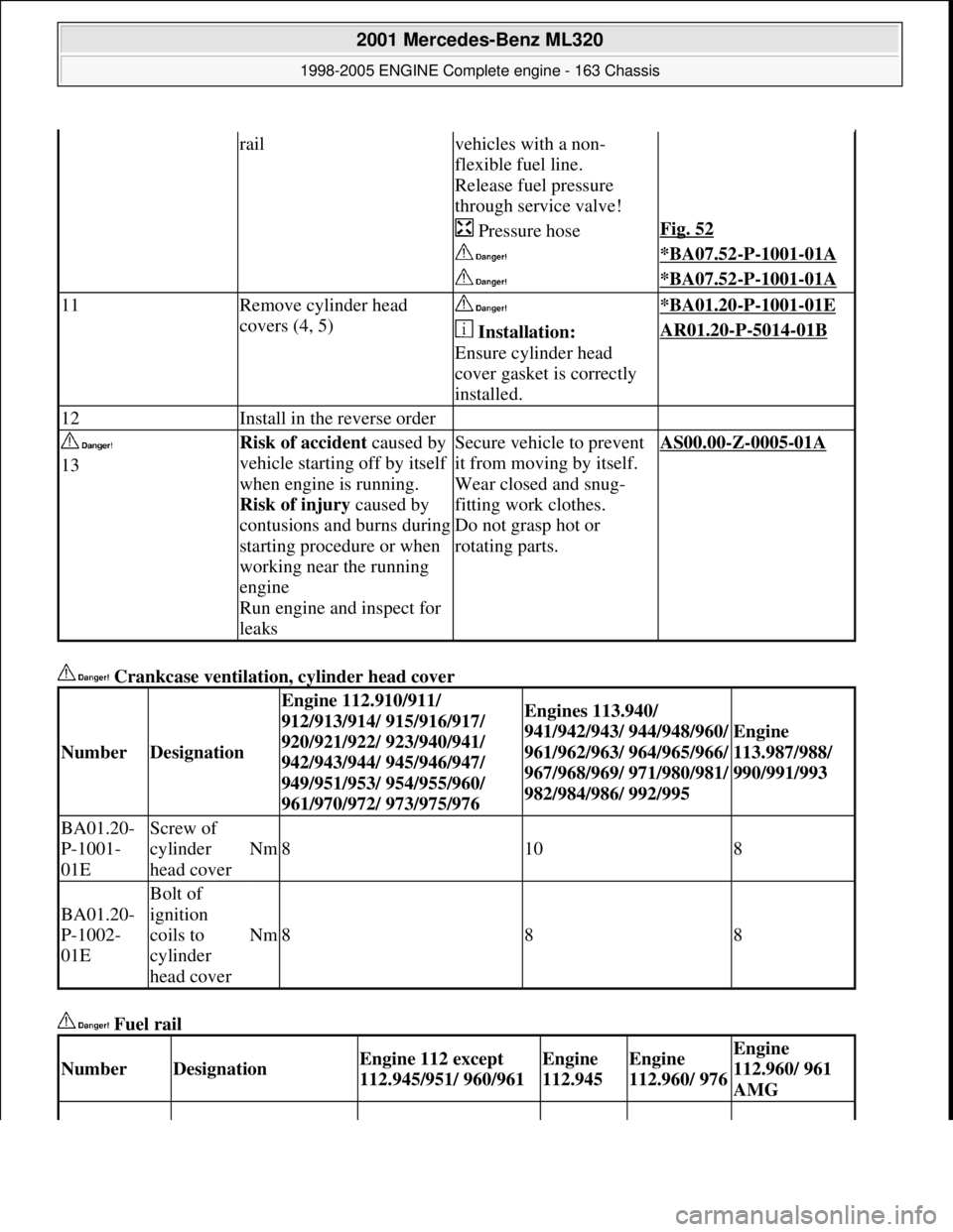
Crankcase ventilation, cylinder head cover
Fuel rail
railvehicles with a non-
flexible fuel line.
Release fuel pressure
through service valve!
Pressure hoseFig. 52
*BA07.52-P-1001-01A
*BA07.52-P-1001-01A
11Remove cylinder head
covers (4, 5) *BA01.20-P-1001-01E
Installation:
Ensure cylinder head
cover gasket is correctly
installed.AR01.20-P-5014-01B
12Install in the reverse order
13Risk of accident caused by
vehicle starting off by itself
when engine is running.
Risk of injury caused by
contusions and burns during
starting procedure or when
working near the running
engine
Run engine and inspect for
leaksSecure vehicle to prevent
it from moving by itself.
Wear closed and snug-
fitting work clothes.
Do not grasp hot or
rotating parts.AS00.00-Z-0005-01A
NumberDesignation
Engine 112.910/911/
912/913/914/ 915/916/917/
920/921/922/ 923/940/941/
942/943/944/ 945/946/947/
949/951/953/ 954/955/960/
961/970/972/ 973/975/976Engines 113.940/
941/942/943/ 944/948/960/
961/962/963/ 964/965/966/
967/968/969/ 971/980/981/
982/984/986/ 992/995
Engine
113.987/988/
990/991/993
BA01.20-
P-1001-
01EScrew of
cylinder
head cover
Nm8108
BA01.20-
P-1002-
01E
Bolt of
ignition
coils to
cylinder
head cover
Nm888
NumberDesignationEngine 112 except
112.945/951/ 960/961Engine
112.945Engine
112.960/ 976Engine
112.960/ 961
AMG
2001 Mercedes-Benz ML320
1998-2005 ENGINE Complete engine - 163 Chassis
me
Saturday, October 02, 2010 3:17:56 PMPage 64 © 2006 Mitchell Repair Information Company, LLC.