radio antenna MERCEDES-BENZ ML430 1997 Complete Owner's Guide
[x] Cancel search | Manufacturer: MERCEDES-BENZ, Model Year: 1997, Model line: ML430, Model: MERCEDES-BENZ ML430 1997Pages: 4133, PDF Size: 88.89 MB
Page 1616 of 4133
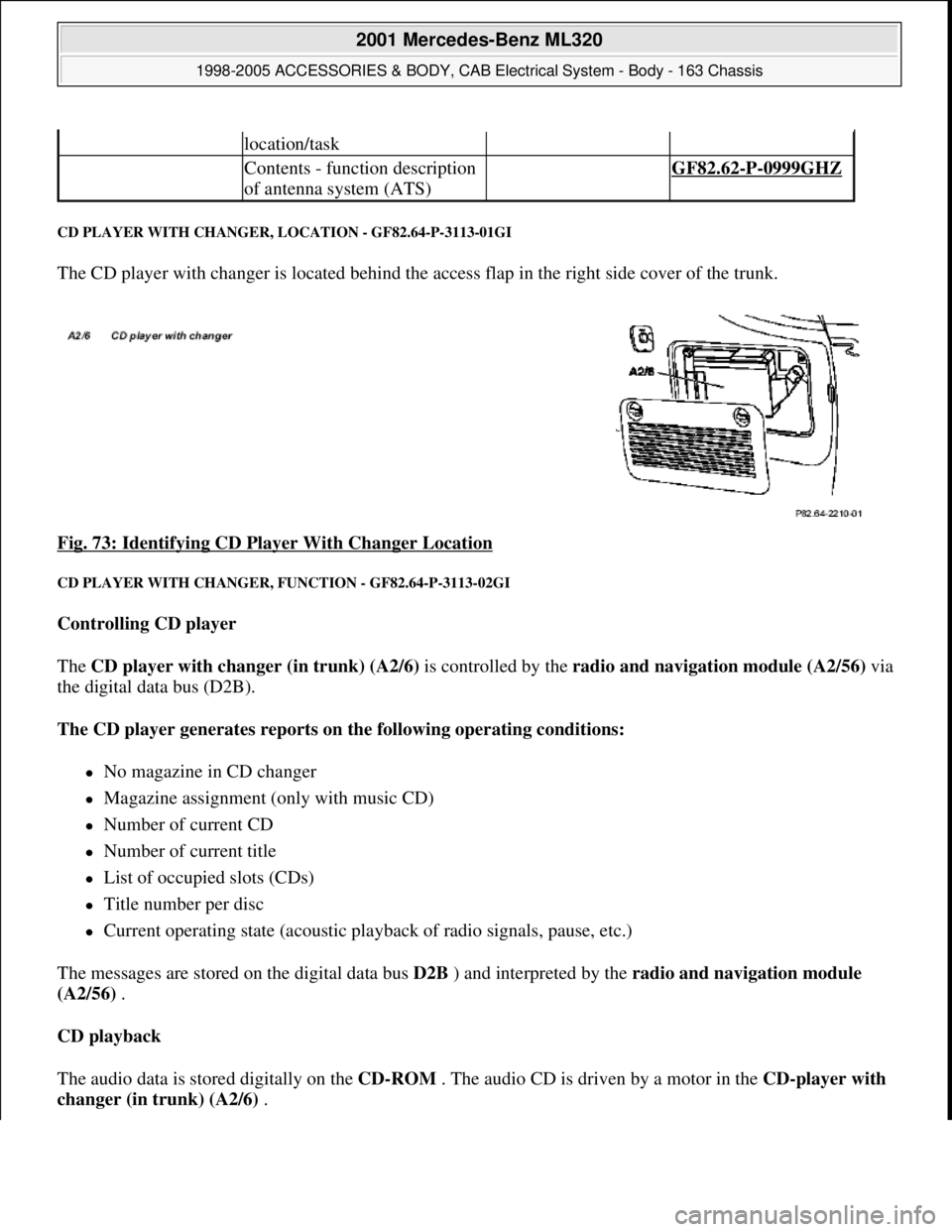
CD PLAYER WITH CHANGER, LOCATION - GF82.64-P-3113-01GI
The CD player with changer is located behind the access flap in the right side cover of the trunk.
Fig. 73: Identifying CD Player With Changer Location
CD PLAYER WITH CHANGER, FUNCTION - GF82.64-P-3113-02GI
Controlling CD player
The CD player with changer (in trunk) (A2/6) is controlled by the radio and navigation module (A2/56)via
the digital data bus (D2B).
The CD player generates reports on the following operating conditions:
No magazine in CD changer
Magazine assignment (only with music CD)
Number of current CD
Number of current title
List of occupied slots (CDs)
Title number per disc
Current operating state (acoustic playback of radio signals, pause, etc.)
The messages are stored on the digital data bus D2B ) and interpreted by the radio and navigation module
(A2/56) .
CD playback
The audio data is stored digitally on the CD-ROM . The audio CD is driven by a motor in the CD-player with
changer (in trunk) (A2/6) .
location/task
Contents - function description
of antenna system (ATS) GF82.62-P-0999GHZ
2001 Mercedes-Benz ML320
1998-2005 ACCESSORIES & BODY, CAB Electrical System - Body - 163 Chassis
me
Saturday, October 02, 2010 3:30:06 PMPage 121 © 2006 Mitchell Repair Information Company, LLC.
Page 1622 of 4133
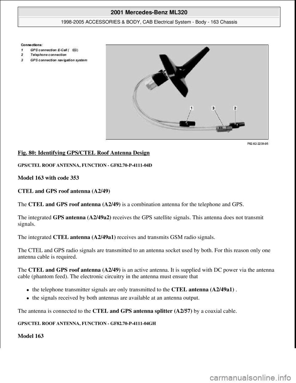
Fig. 80: Identifying GPS/CTEL Roof Antenna Design
GPS/CTEL ROOF ANTENNA, FUNCTION - GF82.70-P-4111-04D
Model 163 with code 353
CTEL and GPS roof antenna (A2/49)
The CTEL and GPS roof antenna (A2/49) is a combination antenna for the telephone and GPS.
The integrated GPS antenna (A2/49a2) receives the GPS satellite signals. This antenna does not transmit
signals.
The integrated CTEL antenna (A2/49a1) receives and transmits GSM radio signals.
The CTEL and GPS radio signals are transmitted to an antenna socket used by both. For this reason only one
antenna cable is required.
The CTEL and GPS roof antenna (A2/49) is an active antenna. It is supplied with DC power via the antenna
cable (phantom feed). The electronic circuitry in the antenna must ensure that
the telephone transmitter signals are only transmitted to the CTEL antenna (A2/49a1) .
the signals received by both antennas are available at an antenna output.
The antenna is connected to the CTEL and GPS antenna splitter (A2/57) by a coaxial cable.
GPS/CTEL ROOF ANTENNA, FUNCTION - GF82.70-P-4111-04GH
Model 163
2001 Mercedes-Benz ML320
1998-2005 ACCESSORIES & BODY, CAB Electrical System - Body - 163 Chassis
me
Saturday, October 02, 2010 3:30:06 PMPage 127 © 2006 Mitchell Repair Information Company, LLC.
Page 1623 of 4133
Function up to 31.8.01
The GPS/CTEL roof antenna (A2/49) is a combination antenna for telephone and GPS.
The CTEL and GPS roof antenna (A2/49) receives the GPS satellite signals. No GPS signals are transmitted
over this range of the antenna.
The CTEL and GPS roof antenna (A2/49) receives and transmits the GSM radio signals.
The radio signals for CTEL and GPS are transmitted to the CTEL and GPS antenna splitter (A2/57) via a
common antenna cable.
The CTEL and GPS roof antenna (A2/49) is an active antenna .
It is supplied with direct voltage via the antenna cable ( phantom feed ). The electronics in the antenna must
ensure that the
transmission signals of the cellular telephone are transmitted by the CTEL and GPS roof antenna
(A2/49)
the received signals of both antennas are made available to an antenna output.
The antenna is linked via a coaxial cable to the CTEL and GPS antenna splitter (A2/57) .
Function as of 01.09.01
The CTEL and GPS roof antenna (A2/49) is a new version of the combination antenna for CTEL and GPS.
It has an integrated antenna splitter and an antenna amplifier, which eliminates the need for the CTEL and
GPS antenna splitter (A2/57) . splitter
The CTEL and GPS roof antenna (A2/49) has connections for
Cellular telephone,
GPS navigation system and
GPS E-Call ( )
GPS/TELEPHONE ROOF ANTENNA, LOCATION/TASK/DESIGN/FUNCTION - GF82.70-P-4111A
MODELS 140, 210 up to 31.5.98 with CODE (348) TELE AID emergency call system
MODELS 129, 202, 208.3, 210 as of 6/198, 220 with CODE (347) TELE AID emergency call system (D2B)
MODEL 140 as of 1.1.98, 168, 202, 208.3, 210.0 as of 1.1.98, 210.2 with CODE (351) Auto pilot system
(APS)
MODELS 163,168, 208.3, 210 with CODE (353) Audio 30 APS
2001 Mercedes-Benz ML320
1998-2005 ACCESSORIES & BODY, CAB Electrical System - Body - 163 Chassis
me
Saturday, October 02, 2010 3:30:06 PMPage 128 © 2006 Mitchell Repair Information Company, LLC.
Page 1624 of 4133
MODELS 163, 208.3, 210, 220 with CODE (352a) COMAND operating and display system with CODE
(353) Audio 30 APS with CODE (853) MB standard CTEL telephone with CODE (854) MB portable
CTEL telephone with CODE (855) TELE AID
MODEL 163 with CODE (522) Modular control system (MCS) Radio USA
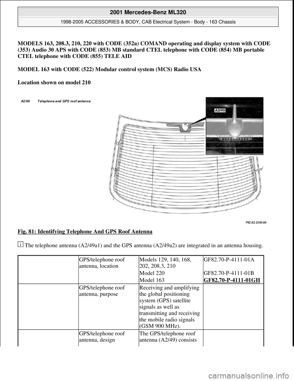
Location shown on model 210
Fig. 81: Identifying Telephone And GPS Roof Antenna
The telephone antenna (A2/49a1) and the GPS antenna (A2/49a2) are integrated in an antenna housing.
GPS/telephone roof
antenna, locationModels 129, 140, 168,
202, 208.3, 210GF82.70-P-4111-01A
Model 220GF82.70-P-4111-01B
Model 163GF82.70-P-4111-01GH
GPS/telephone roof
antenna, purposeReceiving and amplifying
the global positioning
system (GPS) satellite
signals as well as
transmitting and receiving
the mobile radio signals
(GSM 900 MHz).
GPS/telephone roof
antenna, designThe GPS/telephone roof
antenna (A2/49) consists
2001 Mercedes-Benz ML320
1998-2005 ACCESSORIES & BODY, CAB Electrical System - Body - 163 Chassis
me
Saturday, October 02, 2010 3:30:06 PMPage 129 © 2006 Mitchell Repair Information Company, LLC.
Page 1625 of 4133
MODULAR CONTROL SYSTEM (MCS), FUNCTION - GF82.85-P-0011GI
MODEL 163 as of 1.9.01 with CODE (522) Modular control system (MCS) radio USA with CODE (357)
Navigation system - additional unit with CODE (818b) Single CD player - additional unit with CODE
(819) 6-disk CD changer in trunk with CODE (491) U.S. version
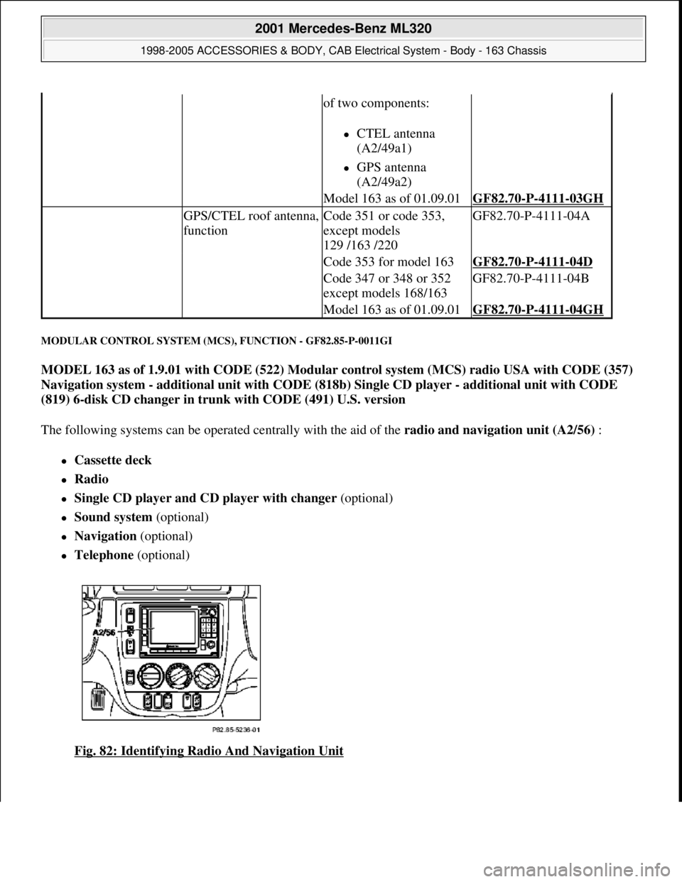
The following systems can be operated centrally with the aid of the radio and navigation unit (A2/56) :
Cassette deck
Radio
Single CD player and CD player with changer (optional)
Sound system (optional)
Navigation (optional)
Telephone (optional)
Fig. 82: Identifying Radio And Navigation Unit
of two components:
CTEL antenna
(A2/49a1)
GPS antenna
(A2/49a2)
Model 163 as of 01.09.01GF82.70-P-4111-03GH
GPS/CTEL roof antenna,
functionCode 351 or code 353,
except models
129 /163 /220GF82.70-P-4111-04A
Code 353 for model 163GF82.70-P-4111-04D
Code 347 or 348 or 352
except models 168/163GF82.70-P-4111-04B
Model 163 as of 01.09.01GF82.70-P-4111-04GH
2001 Mercedes-Benz ML320
1998-2005 ACCESSORIES & BODY, CAB Electrical System - Body - 163 Chassis
me
Saturday, October 02, 2010 3:30:06 PMPage 130 © 2006 Mitchell Repair Information Company, LLC.
Page 1629 of 4133
SWITCH ON/OFF BEHAVIOR, FUNCTION - GF82.85-P-2006B
MODEL 163, 168, 170, 203.0 /2 /7, 208, 209.3 /4, 210 with CODE (353) Audio 30 APS
ON/off characteristics
The radio (A2) is switched on by pressing the "ON" button. The radio (A2) likewise switches On automatically
by rotating the ignition key (models 163, 168, 170, 208, 210) or transmitter key (A8/1) (models 203, 209) into
position 1 "circuit 15R ON", provided that it was switched on immediately before the last time "circuit 15R
ON" was switched off. However, if the radio (A2) was switched off last, only the following components are
activated with "circuit 15R ON":
Digital databus (D2B)
Continuous location finding
In this case the display on the radio (A2) remains Off. This allows quick availability of the system when the
"ON" button is then actuated.
Following each switch-on operation, the system returns to the state in which it was before it was last switched
off (e.g. navigation basic menu).
The bus systems and navigation processor for location finding (for quicker readiness for operation) are
already activated when the driver door is opened.
Switch off characteristics
The system is switched off by switching off at the "ON" button or when "circuit 15R ON" is switched off.
The unit switches off automatically after an hour, if when switching on the ignition key (models 163, 168, 170,
208, 210) or transmitter key (A8/1) (models 203, 209) has not been inserted in the ignition switch.
Run-on time/navigation
CTEL mode, functionFor MB CTEL
standard (code 853)
or MB portable
CTEL (code 854).GF82.85-P-2007GH
Voice command, function GF82.85-P-3001GH
Table of contents, function description
of antenna system (ATS) GF82.62-P-0999B
Overview of system components for
cockpit management and data system
(COMAND ),
location/task/design/function GF82.85-P-
9997GHZ
2001 Mercedes-Benz ML320
1998-2005 ACCESSORIES & BODY, CAB Electrical System - Body - 163 Chassis
me
Saturday, October 02, 2010 3:30:06 PMPage 134 © 2006 Mitchell Repair Information Company, LLC.
Page 1632 of 4133
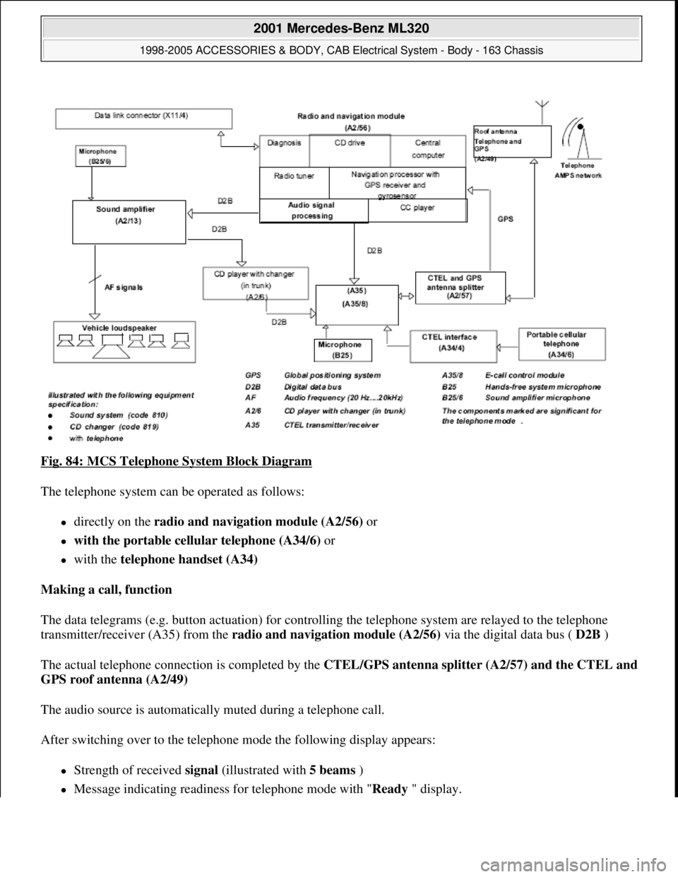
Fig. 84: MCS Telephone System Block Diagram
The telephone system can be operated as follows:
directly on the radio and navigation module (A2/56) or
with the portable cellular telephone (A34/6) or
with the telephone handset (A34)
Making a call, function
The data telegrams (e.g. button actuation) for controlling the telephone system are relayed to the telephone
transmitter/receiver (A35) from the radio and navigation module (A2/56) via the digital data bus ( D2B )
The actual telephone connection is completed by the CTEL/GPS antenna splitter (A2/57) and the CTEL and
GPS roof antenna (A2/49)
The audio source is automatically muted during a telephone call.
After switching over to the telephone mode the following display appears:
Strength of received signal (illustrated with 5 beams )
Message indicating readiness for telephone mode with "Ready" display.
2001 Mercedes-Benz ML320
1998-2005 ACCESSORIES & BODY, CAB Electrical System - Body - 163 Chassis
me
Saturday, October 02, 2010 3:30:06 PMPage 137 © 2006 Mitchell Repair Information Company, LLC.
Page 1634 of 4133
If a name is not available for the stored telephone number, the display is switched over and the
memory location and the telephone number are displayed.
By manually entering 1 or 2 numbers and subsequent actuation of the multifunction key" NAME " or
"NUM " the name stored under this memory location number or the stored telephone number are
indicated.
Pressing " SEND " button completes the desired connection. If no connection is to be completed, the
memory area can be exited by pressing the multifunction key" EXIT ".
Quick dial
When a one or two-digit number is entered and the " SEND " button is actuated the telephone number
stored under this memory location number is dialed.
By pressing and holding one of the number buttons 1 to 9 for more than 2 s the telephone number stored
under this memory location number is dialed. In this case it is not necessary to actuate the " SEND "
button.
Memory location functions 1 number is reserved for emergency !
Redialing
Pressing the" SEND " button without previously entering a telephone number calls up the last 5 selected
telephone numbers on the display. It is possible to select the desired telephone number by pressing the"
joystick " up or down. The connection is completed by actuating the" SEND " button. This area can be
exited by pressing the multifunction key" EXIT ".
Incoming calls
During an incoming call all other audio sources are set to mute and "CALL " appears on the display. The
call can be accepted by pressing the " SEND " button or terminated by pressing the" END " button.
During a call it is possible to continue dialing, e.g. enter a code number for an answering machine.
CASSETTE MODE, FUNCTION - GF82.85-P-2010GI
MODEL 163 as of 1.9.01 with CODE (522) Modular control system (MCS) radio USA with CODE (357)
Navigation system - additional unit with CODE (818b) Single CD player - additional unit with CODE
(491) U.S. version
GPS roof
antenna/telephone,
location/purpose/
design/function GF82.70-P-
4111A
2001 Mercedes-Benz ML320
1998-2005 ACCESSORIES & BODY, CAB Electrical System - Body - 163 Chassis
me
Saturday, October 02, 2010 3:30:06 PMPage 139 © 2006 Mitchell Repair Information Company, LLC.
Page 1638 of 4133
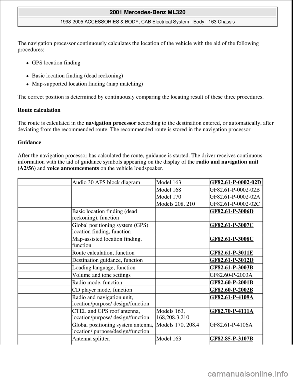
The navigation processor continuously calculates the location of the vehicle with the aid of the following
procedures:
GPS location finding
Basic location finding (dead reckoning)
Map-supported location finding (map matching)
The correct position is determined by continuously comparing the locating result of these three procedures.
Route calculation
The route is calculated in the navigation processor according to the destination entered, or automatically, after
deviating from the recommended route. The recommended route is stored in the navigation processor
Guidance
After the navigation processor has calculated the route, guidance is started. The driver receives continuous
information with the aid of guidance symbols appearing on the display of the radio and navigation unit
(A2/56) and voice announcements on the vehicle loudspeaker.
Audio 30 APS block diagramModel 163GF82.61-P-0002-02D
Model 168GF82.61-P-0002-02B
Model 170GF82.61-P-0002-02A
Models 208, 210GF82.61-P-0002-02C
Basic location finding (dead
reckoning), function GF82.61-P-3006D
Global positioning system (GPS)
location finding, function GF82.61-P-3007C
Map-assisted location finding,
function GF82.61-P-3008C
Route calculation, function GF82.61-P-3011E
Destination guidance, function GF82.61-P-3012D
Loading language, function GF82.61-P-3003B
Volume and tone settings GF82.60-P-2003A
Radio mode, function GF82.60-P-2001B
CD player mode, function GF82.60-P-2002B
Radio and navigation unit,
location/purpose/ design/function GF82.61-P-4109A
CTEL and GPS roof antenna,
location/purpose/ design/functionModels 163,
168,208.3,210GF82.70-P-4111A
Global positioning system antenna,
location/ purpose/design/functionModels 170, 208.4GF82.61-P-4106A
Antenna splitter, Model 163GF82.85-P-3107B
2001 Mercedes-Benz ML320
1998-2005 ACCESSORIES & BODY, CAB Electrical System - Body - 163 Chassis
me
Saturday, October 02, 2010 3:30:06 PMPage 143 © 2006 Mitchell Repair Information Company, LLC.
Page 1654 of 4133
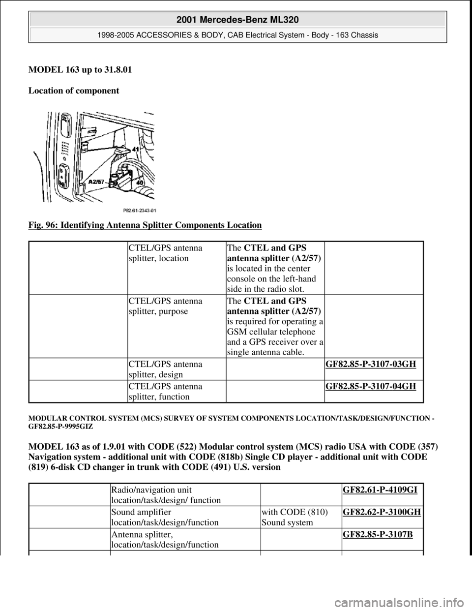
MODEL 163 up to 31.8.01
Location of component
Fig. 96: Identifying Antenna Splitter Components Location
MODULAR CONTROL SYSTEM (MCS) SURVEY OF SYSTEM COMPONENTS LOCATION/TASK/DESIGN/FUNCTION -
GF82.85-P-9995GIZ
MODEL 163 as of 1.9.01 with CODE (522) Modular control system (MCS) radio USA with CODE (357)
Navigation system - additional unit with CODE (818b) Single CD player - additional unit with CODE
(819) 6-disk CD changer in trunk with CODE (491) U.S. version
CTEL/GPS antenna
splitter, locationThe CTEL and GPS
antenna splitter (A2/57)
is located in the center
console on the left-hand
side in the radio slot.
CTEL/GPS antenna
splitter, purposeThe CTEL and GPS
antenna splitter (A2/57)
is required for operating a
GSM cellular telephone
and a GPS receiver over a
single antenna cable.
CTEL/GPS antenna
splitter, design GF82.85-P-3107-03GH
CTEL/GPS antenna
splitter, function GF82.85-P-3107-04GH
Radio/navigation unit
location/task/design/ function GF82.61-P-4109GI
Sound amplifier
location/task/design/functionwith CODE (810)
Sound systemGF82.62-P-3100GH
Antenna splitter,
location/task/design/function GF82.85-P-3107B
2001 Mercedes-Benz ML320
1998-2005 ACCESSORIES & BODY, CAB Electrical System - Body - 163 Chassis
me
Saturday, October 02, 2010 3:30:06 PMPage 159 © 2006 Mitchell Repair Information Company, LLC.