roof rack MERCEDES-BENZ ML430 1997 Complete Service Manual
[x] Cancel search | Manufacturer: MERCEDES-BENZ, Model Year: 1997, Model line: ML430, Model: MERCEDES-BENZ ML430 1997Pages: 4133, PDF Size: 88.89 MB
Page 3752 of 4133
AR46.20-P-0600GH
Removing and installing rack-and-pinion steering
1.3.97
MODEL
163.113 /128 /136 /154 /157 /172 /174 /175
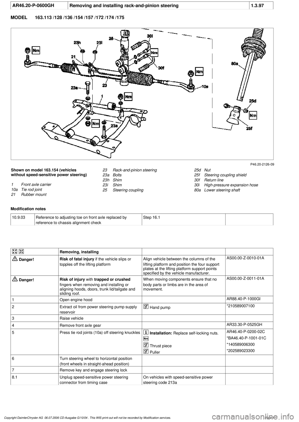
P46.20-2126-09
Shown on model 163.154 (vehicles
without speed-sensitive power steering)
1
Front axle carrier
10a
Tie rod joint
21
Rubber mount
25d
Nut
25f
Steering coupling shield
30f
Return line
30i
High-pressure expansion hose
80a
Lower steering shaft
23
Rack-and-pinion steering
23a
Bolts
23h
Shim
23i
Shim
25
Steering coupling
Modification notes
10.9.03
Reference to adjusting toe on front axle replaced by
reference to chassis alignment check
Step 16.1
Removing, installing
Danger!
Risk of fatal injury
if the vehicle slips or
topples off the lifting platform
Align vehicle between the columns of the
lifting platform and position the four support
plates
at the lifting platform support points
specified by the vehicle manufacturer.
AS00.00-Z-0010-01A
Danger!
Risk of injury
with
trapped or crushed
fingers when removing and installing or
aligning hoods, doors, trunk lid/tailgate and
sliding roof.
When moving components ensure that no
body parts or limbs are in the area of
movement.
AS00.00-Z-0011-01A
1
Open engine hood
AR88.40-P-1000GI
2
Extract oil from power steering pump supply
reservoir
Hand pump
*210589007100
3
Raise vehicle
4
Remove front axle gear
AR33.30-P-0525GH
5
Press tie rod joints (10a) off steering knuckles
Installation:
Replace self-locking nuts.
AR46.40-P-0200-02C
*BA46.40-P-1001-01C
Thrust piece
*140589006300
Puller
*202589023300
6
Turn steering wheel to horizontal position
(front wheels in straight-ahead position)
7
Remove key and engage steering lock
8.1
Unplug speed-sensitive power steering
connector from timing case
On vehicles with speed-sensitive power
steering code 213a
Copyright DaimlerChrysler AG 06.07.2006 CD-Ausgabe G/10/04 . This WIS print-out will not be recorde
d by Modification services.
Page 1
Page 3759 of 4133
AR20.40-P-5000M
Remove/install electric fan
24.8.99
ENGINE
612.963 in MODEL 163.113
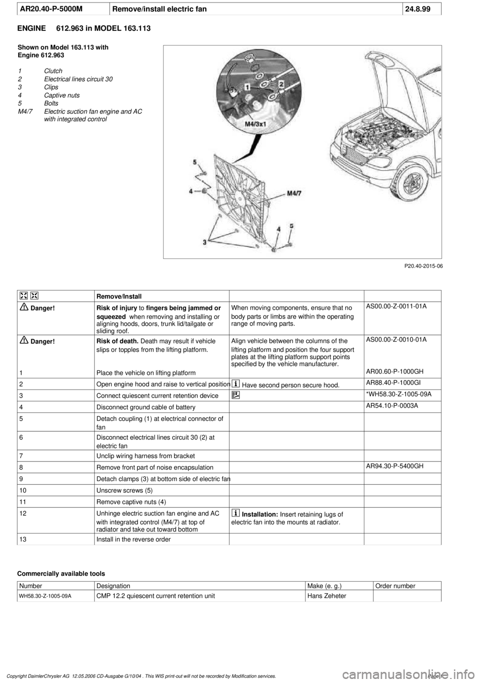
P20.40-2015-06
Shown on Model 163.113 with
Engine 612.963
1
Clutch
2
Electrical lines circuit 30
3
Clips
4
Captive nuts
5
Bolts
M4/7
Electric suction fan engine and AC
with integrated control
Remove/Install
Danger!
Risk of injury
to
fingers being jammed or
squeezed
when removing and installing or
aligning hoods, doors, trunk lid/tailgate or
sliding roof.
When moving components, ensure that no
body parts or limbs are within the operating
range of moving parts.
AS00.00-Z-0011-01A
Danger!
Risk of death.
Death may result if vehicle
slips or topples from the lifting platform.
Align vehicle between the columns of the
lifting platform and position the four support
plates
at the lifting platform support points
specified by the vehicle manufacturer.
AS00.00-Z-0010-01A
1
Place the vehicle on lifting platform
AR00.60-P-1000GH
2
Open engine hood and raise to vertical position
Have second person secure hood.
AR88.40-P-1000GI
3
Connect quiescent current retention device
*WH58.30-Z-1005-09A
4
Disconnect ground cable of battery
AR54.10-P-0003A
5
Detach coupling (1) at electrical connector of
fan
6
Disconnect electrical lines circuit 30 (2) at
electric fan
7
Unclip wiring harness from bracket
8
Remove front part of noise encapsulation
AR94.30-P-5400GH
9
Detach clamps (3) at bottom side of electric fan
10
Unscrew screws (5)
11
Remove captive nuts (4)
12
Unhinge electric suction fan engine and AC
with integrated control (M4/7) at top of
radiator and take out toward bottom
Installation:
Insert retaining lugs of
electric fan into the mounts at radiator.
13
Install in the reverse order
Commercially available tools
Number
Designation
Make (e. g.)
Order number
WH58.30-Z-1005-09A
CMP 12.2 quiescent current retention unit
Hans Zeheter
Copyright DaimlerChrysler AG 12.05.2006 CD-Ausgabe G/10/04 . This WIS print-out will not be recorde
d by Modification services.
Page 1
Page 3786 of 4133
AN68.30-P-0001-02A
Modify roof paneling for installing handle and
clamping strap mount
Model 163.113 /154 #A up to 289564,
#X up to 754619
Model 163.136/ 172
with code (847), 3rd seat row
Handles
Number
Designation
MODEL
Series 163
BA68.70-P-1001-02A
Screw for pivot handle/mount on roof frame
Nm
2.5
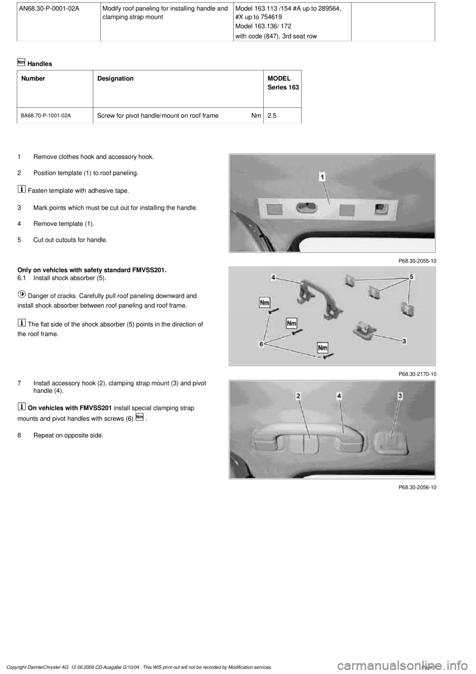
P68.30-2055-10
1
Remove clothes hook and accessory hook.
2
Position template (1) to roof paneling.
Fasten template with adhesive tape.
3
Mark points which must be cut out for installing the handle.
4
Remove template (1).
5
Cut out cutouts for handle.
P68.30-2170-10
Only on vehicles with safety standard FMVSS201.
6.1
Install shock absorber (5).
Danger of cracks. Carefully pull roof paneling downward and
install shock absorber between roof paneling and roof frame.
The flat side of the shock absorber (5) points in the direction of
the roof frame.
P68.30-2056-10
7
Install accessory hook (2), clamping strap mount (3) and pivot
handle (4).
On vehicles with FMVSS201
install special clamping strap
mounts and pivot handles with screws (6)
.
8
Repeat on opposite side.
Copyright DaimlerChrysler AG 12.06.2006 CD-Ausgabe G/10/04 . This WIS print-out will not be recorde
d by Modification services.
Page 1
Page 3815 of 4133
AR91.40-P-2000GHRemove/install seat belts for third row of seats
12.3.97
MODEL
163.113 /128 /136 /154 /157 /172 /175 with CODE (847) 3rd seat row
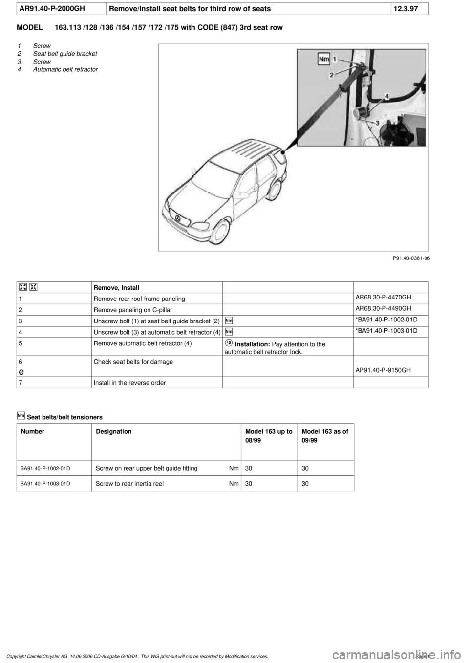
P91.40-0361-06
1
Screw
2
Seat belt guide bracket
3
Screw
4
Automatic belt retractor
Remove, Install
1
Remove rear roof frame paneling
AR68.30-P-4470GH
2
Remove paneling on C-pillar
AR68.30-P-4490GH
3
Unscrew bolt (1) at seat belt guide bracket (2)
*BA91.40-P-1002-01D
4
Unscrew bolt (3) at automatic belt retractor (4)
*BA91.40-P-1003-01D
5
Remove automatic belt retractor (4)
Installation:
Pay attention to the
automatic belt retractor lock.
6
Check seat belts for damage
e
AP91.40-P-9150GH
7
Install in the reverse order
Seat belts/belt tensioners
Number
Designation
Model 163 up to
08/99
Model 163 as of
09/99
BA91.40-P-1002-01D
Screw on rear upper belt guide fitting
Nm
3030
BA91.40-P-1003-01D
Screw to rear inertia reel
Nm
3030
Copyright DaimlerChrysler AG 14.06.2006 CD-Ausgabe G/10/04 . This WIS print-out will not be recorde
d by Modification services.
Page 1