Shutoff valve MERCEDES-BENZ ML430 1997 Complete Repair Manual
[x] Cancel search | Manufacturer: MERCEDES-BENZ, Model Year: 1997, Model line: ML430, Model: MERCEDES-BENZ ML430 1997Pages: 4133, PDF Size: 88.89 MB
Page 2145 of 4133
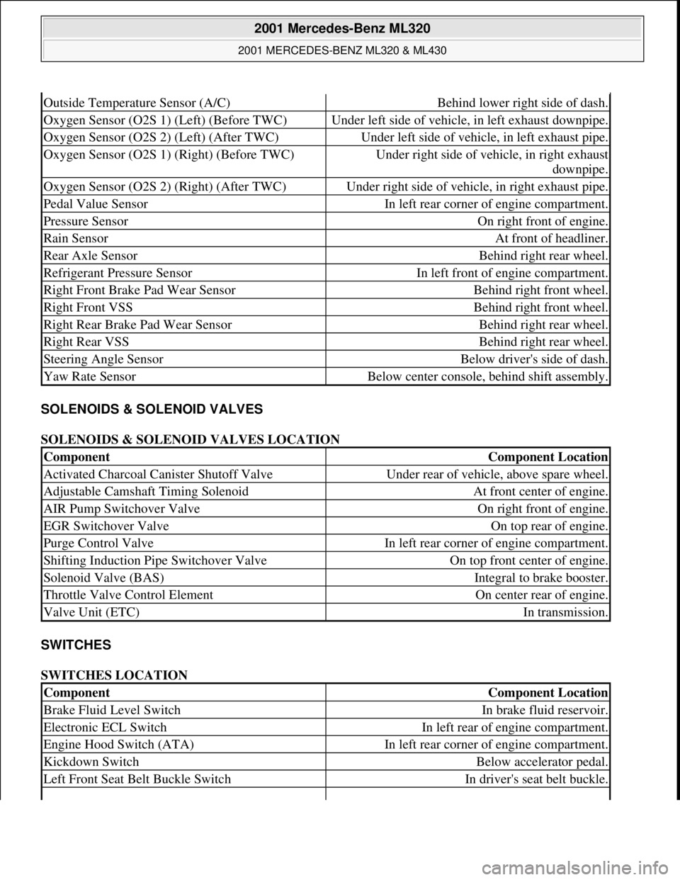
SOLENOIDS & SOLENOID VALVES
SOLENOIDS & SOLENOID VALVES LOCATION
SWITCHES
SWITCHES LOCATION
Outside Temperature Sensor (A/C)Behind lower right side of dash.
Oxygen Sensor (O2S 1) (Left) (Before TWC)Under left side of vehicle, in left exhaust downpipe.
Oxygen Sensor (O2S 2) (Left) (After TWC)Under left side of vehicle, in left exhaust pipe.
Oxygen Sensor (O2S 1) (Right) (Before TWC)Under right side of vehicle, in right exhaust
downpipe.
Oxygen Sensor (O2S 2) (Right) (After TWC)Under right side of vehicle, in right exhaust pipe.
Pedal Value SensorIn left rear corner of engine compartment.
Pressure SensorOn right front of engine.
Rain SensorAt front of headliner.
Rear Axle SensorBehind right rear wheel.
Refrigerant Pressure SensorIn left front of engine compartment.
Right Front Brake Pad Wear SensorBehind right front wheel.
Right Front VSSBehind right front wheel.
Right Rear Brake Pad Wear SensorBehind right rear wheel.
Right Rear VSSBehind right rear wheel.
Steering Angle SensorBelow driver's side of dash.
Yaw Rate SensorBelow center console, behind shift assembly.
ComponentComponent Location
Activated Charcoal Canister Shutoff ValveUnder rear of vehicle, above spare wheel.
Adjustable Camshaft Timing SolenoidAt front center of engine.
AIR Pump Switchover ValveOn right front of engine.
EGR Switchover ValveOn top rear of engine.
Purge Control ValveIn left rear corner of engine compartment.
Shifting Induction Pipe Switchover ValveOn top front center of engine.
Solenoid Valve (BAS)Integral to brake booster.
Throttle Valve Control ElementOn center rear of engine.
Valve Unit (ETC)In transmission.
ComponentComponent Location
Brake Fluid Level SwitchIn brake fluid reservoir.
Electronic ECL SwitchIn left rear of engine compartment.
Engine Hood Switch (ATA)In left rear corner of engine compartment.
Kickdown SwitchBelow accelerator pedal.
Left Front Seat Belt Buckle SwitchIn driver's seat belt buckle.
2001 Mercedes-Benz ML320
2001 MERCEDES-BENZ ML320 & ML430
me
Saturday, October 02, 2010 3:21:17 PMPage 5 © 2006 Mitchell Repair Information Company, LLC.
Page 2171 of 4133
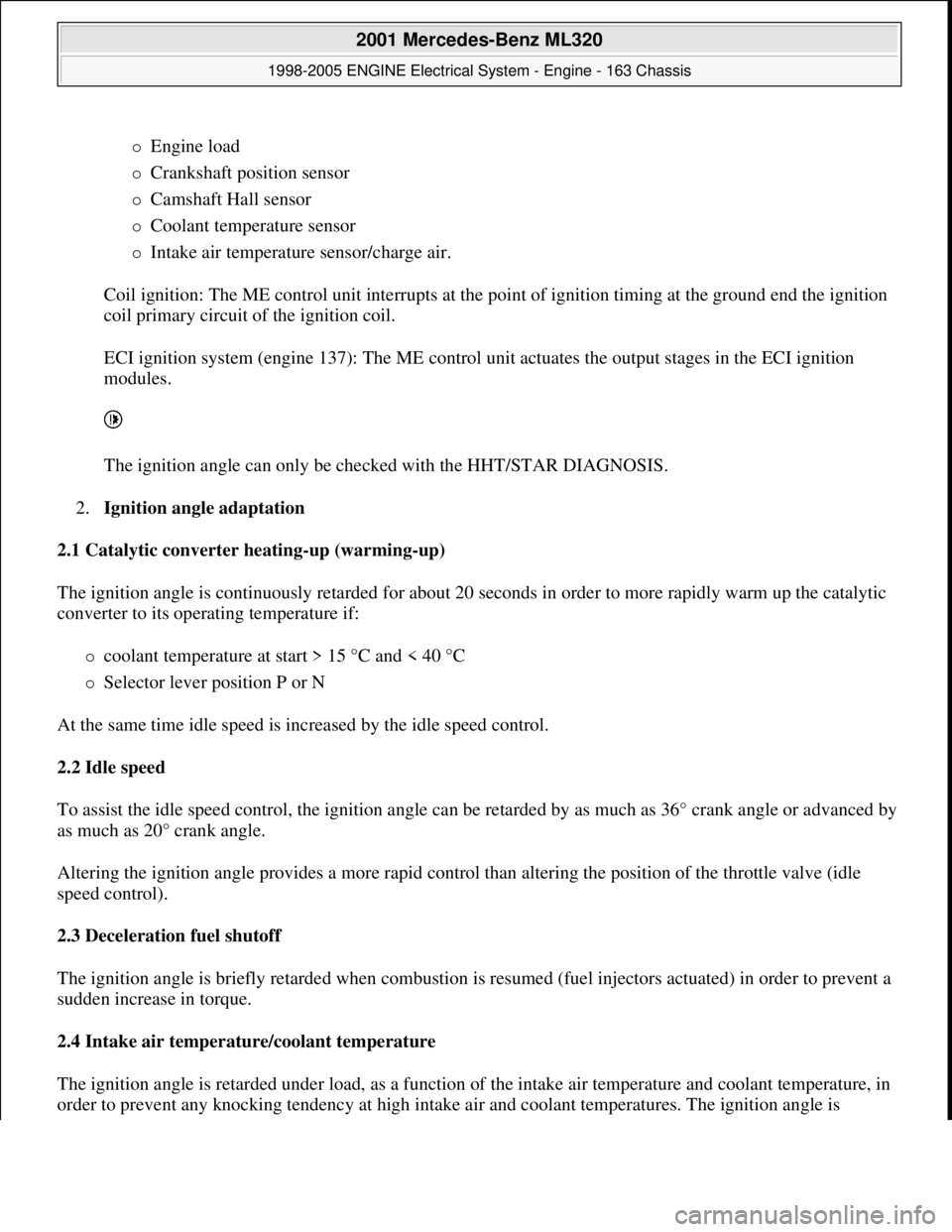
Engine load
Crankshaft position sensor
Camshaft Hall sensor
Coolant temperature sensor
Intake air temperature sensor/charge air.
Coil ignition: The ME control unit interrupts at the point of ignition timing at the ground end the ignition
coil primary circuit of the ignition coil.
ECI ignition system (engine 137): The ME control unit actuates the output stages in the ECI ignition
modules.
The ignition angle can only be checked with the HHT/STAR DIAGNOSIS.
2.Ignition angle adaptation
2.1 Catalytic converter heating-up (warming-up)
The ignition angle is continuously retarded for about 20 seconds in order to more rapidly warm up the catalytic
converter to its operating temperature if:
coolant temperature at start > 15 °C and < 40 °C
Selector lever position P or N
At the same time idle speed is increased by the idle speed control.
2.2 Idle speed
To assist the idle speed control, the ignition angle can be retarded by as much as 36° crank angle or advanced by
as much as 20° crank angle.
Altering the ignition angle provides a more rapid control than altering the position of the throttle valve (idle
speed control).
2.3 Deceleration fuel shutoff
The ignition angle is briefly retarded when combustion is resumed (fuel injectors actuated) in order to prevent a
sudden increase in torque.
2.4 Intake air temperature/coolant temperature
The ignition angle is retarded under load, as a function of the intake air temperature and coolant temperature, in
order to prevent an
y knocking tendency at high intake air and coolant temperatures. The ignition angle is
2001 Mercedes-Benz ML320
1998-2005 ENGINE Electrical System - Engine - 163 Chassis
me
Saturday, October 02, 2010 3:18:54 PMPage 17 © 2006 Mitchell Repair Information Company, LLC.
Page 2240 of 4133

Fuel pump (gear pump) and electric
shutoff valve can remain on engine.
15
Check injection system for leakage.
16
Check with HHT/DAS for proper
function (check actual value).
17
Read DTC memory and erase after
checking.
Copyright DaimlerChrysler AG 28.05.2006 CD-Ausgabe G/10/04 . This WIS print-out will not be recorde
d by Modification services.
Page 2
Page 2254 of 4133
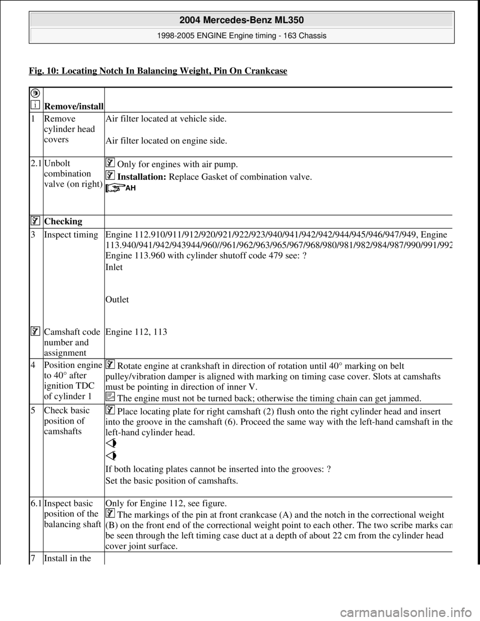
Fig. 10: Locating Notch In Balancing Weight, Pin On Crankcase
Remove/install
1Remove
cylinder head
covers Air filter located
at vehicle side.
Air filter located on engine side.
2.1Unbolt
combination
valve (on right) Only for engines with air pump.
Installation: Replace Gasket of combination valve.
Checking
3Inspect timing Engine 112.910/911/912/920/921/ 922/923/940/941/942/942/944/945/946/947/949, Engine
113.940/941/942/943944/960//961/962/963/965/ 967/968/980/981/982/984/987/990/991/99
2
Engine 113.960 with cylinder shutoff code 479 see: ?
Inlet
Outlet
Camshaft code
number and
assignmentEngine 112, 113
4Position engine
to 40° after
ignition TDC
of cylinder 1 Rotate engine at crankshaft in direct ion of rotation until 40° marking on belt
pulley/vibration damper is aligned with mark ing on timing case cover. Slots at camshafts
must be pointing in di rection of inner V.
The engine must not be turned back; otherwise the timing chain can get jammed.
5Check basic
position of
camshafts Place locating plate for right camshaft (2) fl
ush onto the right cylinder head and insert
into the groove in the camshaft (6). Proceed the same way with the left-hand camshaft in th
e
left-hand cylinder head.
If both locating plates cannot be inserted into the grooves: ?
Set the basic position of camshafts.
6.1Inspect basic
position of the
balancing shaftOnly for Engine 112, see figure.
The markings of the pin at front crankcase (A) and the notch in the correctional weight
(B) on the front end of the corr ectional weight point to each ot her. The two scribe marks ca
n
be seen through the left timing case duct at a depth of about 22 cm from the cylinder head
cover joint surface.
7Install in the
2004 Mercedes-Benz ML350
1998-2005 ENGINE Engine timing - 163 Chassis
me
Saturday, October 02, 2010 3:39:37 PMPage 13 © 2006 Mitchell Repair Information Company, LLC.
Page 2271 of 4133
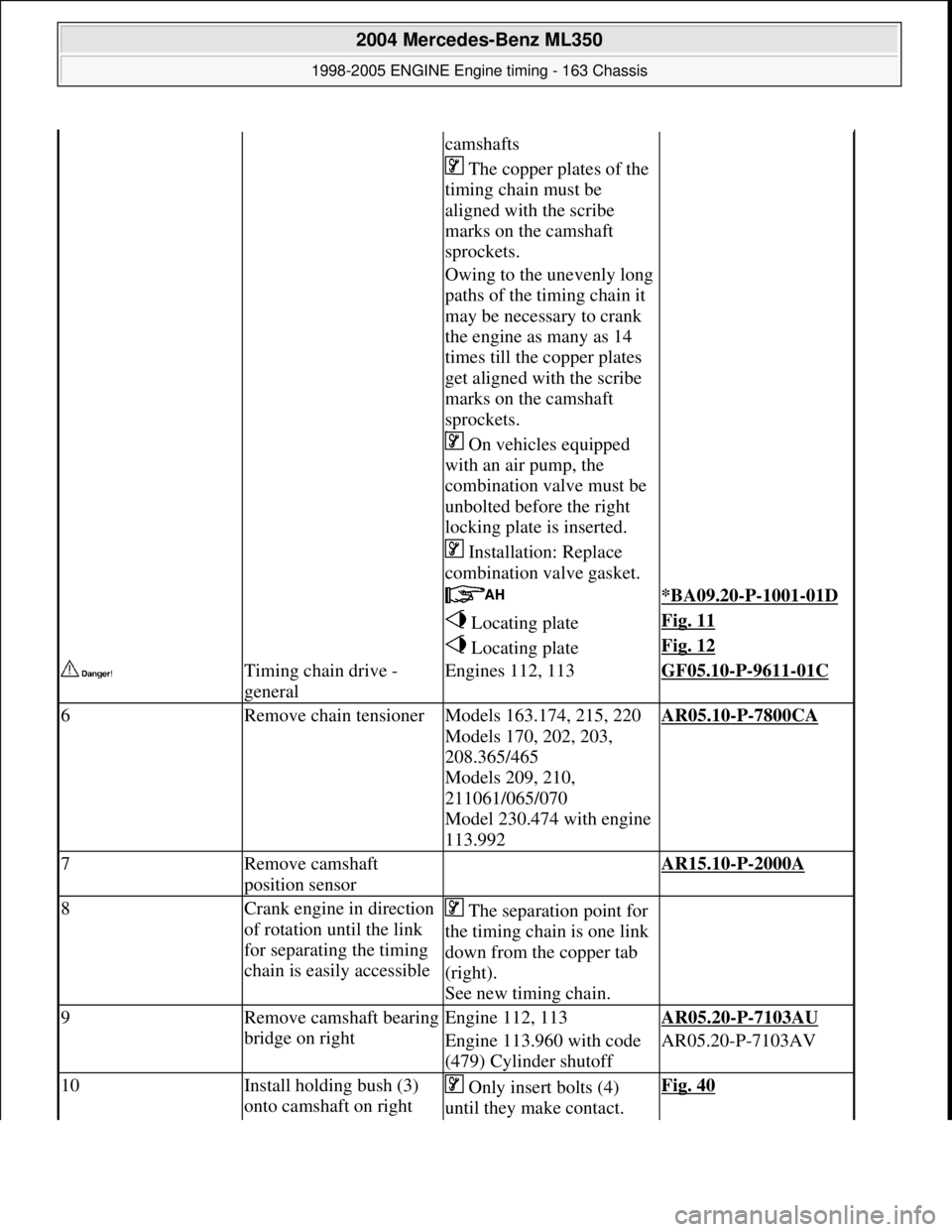
camshafts
The copper plates of the
timing chain must be
aligned with the scribe
marks on the camshaft
sprockets.
Owing to the unevenly long
paths of the timing chain it
may be necessary to crank
the engine as many as 14
times till the copper plates
get aligned with the scribe
marks on the camshaft
sprockets.
On vehicles equipped
with an air pump, the
combination valve must be
unbolted before the right
locking plate is inserted.
Installation: Replace
combination valve gasket.
*BA09.20-P-1001-01D
Locating plateFig. 11
Locating plateFig. 12
Timing chain drive -
generalEngines 112, 113GF05.10-P-9611-01C
6Remove chain tensionerModels 163.174, 215, 220
Models 170, 202, 203,
208.365/465
Models 209, 210,
211061/065/070
Model 230.474 with engine
113.992AR05.10-P-7800CA
7Remove camshaft
position sensor AR15.10-P-2000A
8Crank engine in direction
of rotation until the link
for separating the timing
chain is easily accessible The separation point for
the timing chain is one link
down from the copper tab
(right).
See new timing chain.
9Remove camsha ft bearing
bridge on rightEngine 112, 113AR05.20-P-7103AU
Engine 113.960 with code
(479) Cylinder shutoffAR05.20-P-7103AV
10Install holding bush (3)
onto camshaft on right Only insert bolts (4)
until they make contact. Fig. 40
2004 Mercedes-Benz ML350
1998-2005 ENGINE Engine timing - 163 Chassis
me
Saturday, October 02, 2010 3:39:37 PMPage 30 © 2006 Mitchell Repair Information Company, LLC.
Page 2278 of 4133
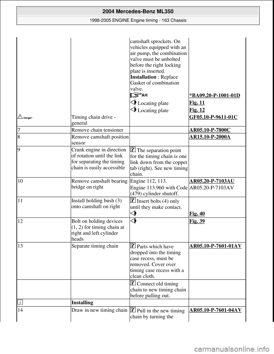
camshaft sprockets. On
vehicles equipped with an
air pump, the combination
valve must be unbolted
before the right locking
plate is inserted.
Installation : Replace
Gasket of combination
valve.
*BA09.20-P-1001-01D
Locating plateFig. 11
Locating plateFig. 12
Timing chain drive -
general GF05.10-P-9611-01C
7Remove chain tensioner AR05.10-P-7800C
8Remove camshaft position
sensor AR15.10-P-2000A
9Crank engine in direction
of rotation until the link
for separating the timing
chain is easily accessible The separation point
for the timing chain is one
link down from the copper
tab (right). See new timing
chain.
10Remove camsha ft bearing
bridge on rightEngine 112, 113.AR05.20-P-7103AU
Engine 113.960 with Code
(479) cylinder shutoff.AR05.20-P-7103AV
11Install holding bush (3)
onto camshaft on right Insert bolts (4) only
until they make contact.
Fig. 40
12Bolt on holding devices
(1, 2) for timing chain at
right and left cylinder
heads Fig. 39
13Separate timing chain Parts which have
dropped into the timing
case recess, must be
removed. Cover over
timing case recess with a
clean cloth.AR05.10-P-7601-01AV
Connect old timing
chain to new timing chain
before pulling out.
Installing
14Draw in new timing chain Pull in the new timing
chain by turning the AR05.10-P-7601-04AV
2004 Mercedes-Benz ML350
1998-2005 ENGINE Engine timing - 163 Chassis
me
Saturday, October 02, 2010 3:39:37 PMPage 37 © 2006 Mitchell Repair Information Company, LLC.
Page 2875 of 4133
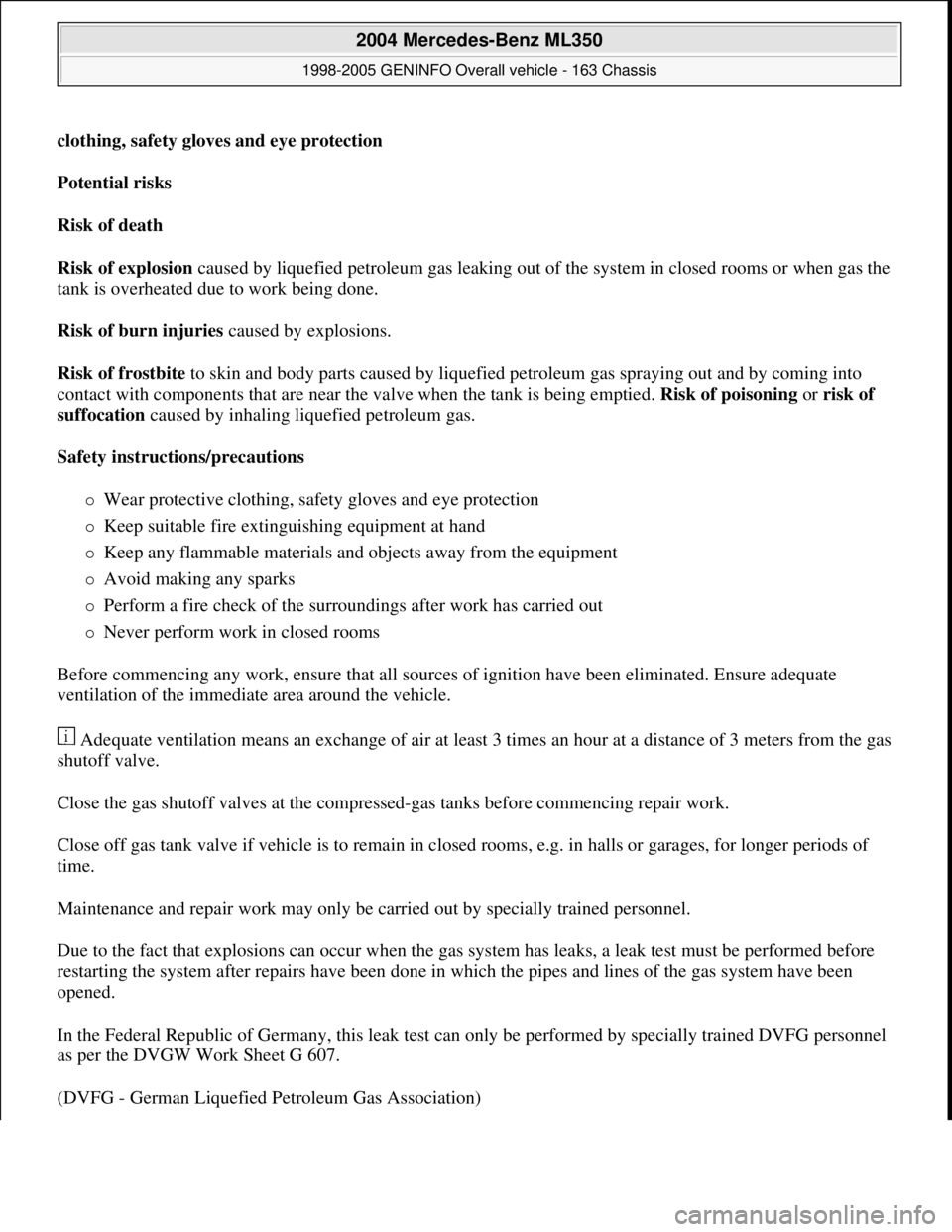
clothing, safety gloves and eye protection
Potential risks
Risk of death
Risk of explosion caused by liquefied petroleum gas leaking out of the system in closed rooms or when gas the
tank is overheated due to work being done.
Risk of burn injuries caused by explosions.
Risk of frostbite to skin and body parts caused by liquefied petroleum gas spraying out and by coming into
contact with components that are near the valve when the tank is being emptied. Risk of poisoning or risk of
suffocation caused by inhaling liquefied petroleum gas.
Safety instructions/precautions
Wear protective clothing, safety gloves and eye protection
Keep suitable fire extinguishing equipment at hand
Keep any flammable materials and objects away from the equipment
Avoid making any sparks
Perform a fire check of the surroundings after work has carried out
Never perform work in closed rooms
Before commencing any work, ensure that all sources of ignition have been eliminated. Ensure adequate
ventilation of the immediate area around the vehicle.
Adequate ventilation means an exchange of air at least 3 times an hour at a distance of 3 meters from the gas
shutoff valve.
Close the gas shutoff valves at the compressed-gas tanks before commencing repair work.
Close off gas tank valve if vehicle is to remain in closed rooms, e.g. in halls or garages, for longer periods of
time.
Maintenance and repair work may only be carried out by specially trained personnel.
Due to the fact that explosions can occur when the gas system has leaks, a leak test must be performed before
restarting the system after repairs have been done in which the pipes and lines of the gas system have been
opened.
In the Federal Republic of Germany, this leak test can only be performed by specially trained DVFG personnel
as per the DVGW Work Sheet G 607.
(DVFG - German Liquefied Petroleum Gas Association)
2004 Mercedes-Benz ML350
1998-2005 GENINFO Overall vehicle - 163 Chassis
me
Saturday, October 02, 2010 3:47:48 PMPage 230 © 2006 Mitchell Repair Information Company, LLC.
Page 3854 of 4133
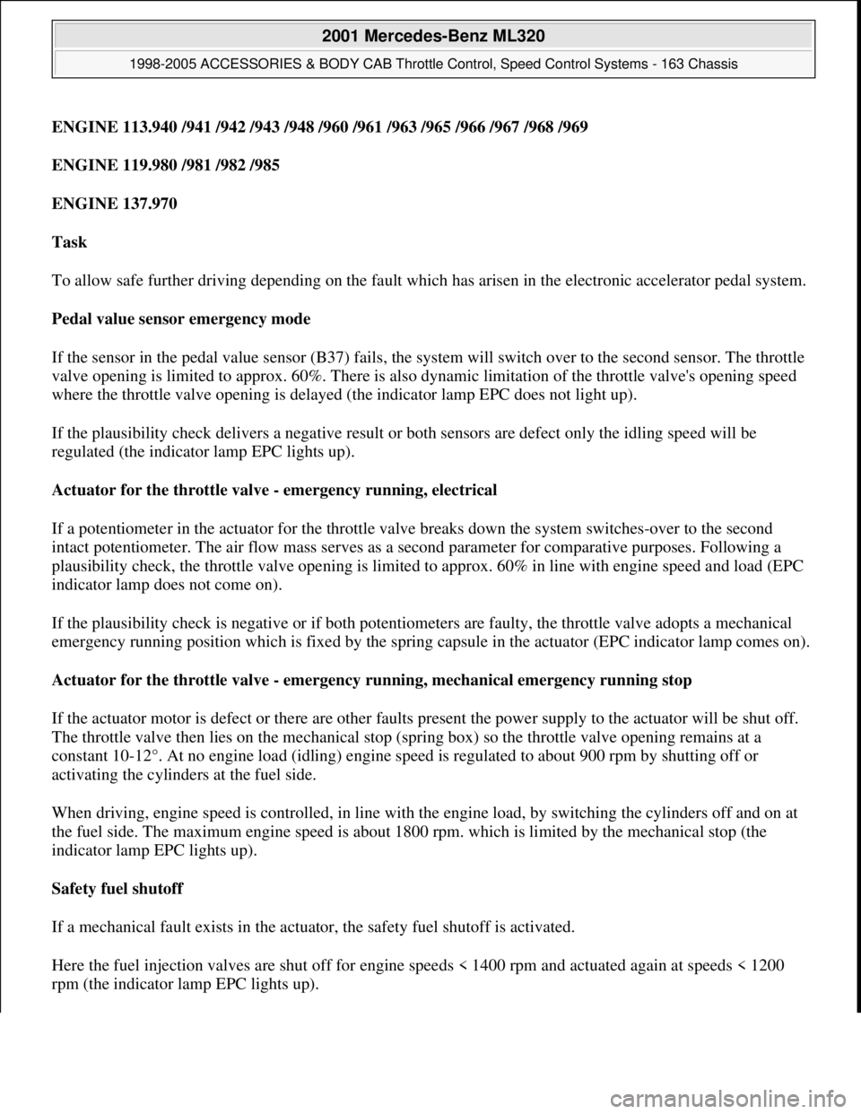
ENGINE 113.940 /941 /942 /943 /948 /960 /961 /963 /965 /966 /967 /968 /969
ENGINE 119.980 /981 /982 /985
ENGINE 137.970
Task
To allow safe further driving depending on the fault which has arisen in the electronic accelerator pedal system.
Pedal value sensor emergency mode
If the sensor in the pedal value sensor (B37) fails, the system will switch over to the second sensor. The throttle
valve opening is limited to approx. 60%. There is also dynamic limitation of the throttle valve's opening speed
where the throttle valve opening is delayed (the indicator lamp EPC does not light up).
If the plausibility check delivers a negative result or both sensors are defect only the idling speed will be
regulated (the indicator lamp EPC lights up).
Actuator for the throttle valve - emergency running, electrical
If a potentiometer in the actuator for the throttle valve breaks down the system switches-over to the second
intact potentiometer. The air flow mass serves as a second parameter for comparative purposes. Following a
plausibility check, the throttle valve opening is limited to approx. 60% in line with engine speed and load (EPC
indicator lamp does not come on).
If the plausibility check is negative or if both potentiometers are faulty, the throttle valve adopts a mechanical
emergency running position which is fixed by the spring capsule in the actuator (EPC indicator lamp comes on).
Actuator for the throttle valve - emergency running, mechanical emergency running stop
If the actuator motor is defect or there are other faults present the power supply to the actuator will be shut off.
The throttle valve then lies on the mechanical stop (spring box) so the throttle valve opening remains at a
constant 10-12°. At no engine load (idling) engine speed is regulated to about 900 rpm by shutting off or
activating the cylinders at the fuel side.
When driving, engine speed is controlled, in line with the engine load, by switching the cylinders off and on at
the fuel side. The maximum engine speed is about 1800 rpm. which is limited by the mechanical stop (the
indicator lamp EPC lights up).
Safety fuel shutoff
If a mechanical fault exists in the actuator, the safety fuel shutoff is activated.
Here the fuel injection valves are shut off for engine speeds < 1400 rpm and actuated again at speeds < 1200
rpm (the indicator lamp EPC li
ghts up).
2001 Mercedes-Benz ML320
1998-2005 ACCESSORIES & BODY CAB Throttle Control, Speed Control Systems - 163 Chassis
me
Saturday, October 02, 2010 3:36:27 PMPage 14 © 2006 Mitchell Repair Information Company, LLC.