battery MERCEDES-BENZ ML430 2002 W163 User Guide
[x] Cancel search | Manufacturer: MERCEDES-BENZ, Model Year: 2002, Model line: ML430, Model: MERCEDES-BENZ ML430 2002 W163Pages: 342, PDF Size: 13.75 MB
Page 169 of 342
166 Tele Aid
Te ch n i c a l
data Instruments
and controlsOperationDrivingInstrument
cluster displayPractical hints Car care Index
Tele Aid (optional for Canada)
Important!
The initial activation of the Tele Aid system may only be
performed by completing the subscriber agreement and
placing an acquaintance call using the “SOS” button.
Failure to complete either of these steps will result in a
system that is not activated. If the system is not
activated the indicator lamp in the “SOS” button stays
on after turning electronic key in starter switch to
position 2 and the message “TELE AID – NOT
ACTIVATED” will be shown in the MCS display for
approx. 10 seconds.
If you have any questions regarding activation, please
call the Response Center at 1-800-756-9018 (in the USA)
or 1-888-923-8367 (in Canada).
(Te l ematic Alarm Identification on Demand)
The Tele Aid system consists of three types of response;
automatic and manual emergency, roadside assistance
and information.The Tele Aid system is operational providing that the
vehicle’s battery is charged, properly connected, not
damaged and cellular and GPS coverage is available.
The speaker volume of a Tele Aid call can be adjusted
using the volume control on the MCS unit. To activate,
press the “SOS” button, the Roadside Assistance
button• or the Information button¡, depending
on the type of response required.
Shortly after the completion of your Acquaintance Call,
you will receive a user ID and password via first call
mail. By visiting www.mbusa.com and selecting
“Tele Aid” (USA only), you will have access to account
information, remote door unlock, Info Services
* profile
and more.
* OptionalSystem self-check
Initially, after turning the key in steering lock to
position 2, malfunctions are detected and indicated (the
indicator lamps in the “SOS” button, the Roadside
Assistance button• and Information button¡
stay on longer than 10 seconds or do not come on). The
message “TELE AID – PLEASE VISIT WORKSHOP”
appears in the MCS display.
Page 184 of 342
181 Steering lock
Te ch n i c a l
data Instruments
and controlsOperationDrivingInstrument
cluster displayPractical hints Car care Index Caution!
To prevent accelerated battery discharge and a possible
dead battery, always remove the key from the steering
lock. Do not leave the key in steering lock position 0.
Notes:
A warning sounds when the driver’s door is opened
while the key is in steering lock position 1 or 0.
With the engine at idle speed, the charging rate of the
alternator (output) is limited.It is therefore recommended that you turn off
unnecessary electrical consumers while driving in stop-
and-go traffic. This precaution helps to avoid draining of
the battery.
Unnecessary strain on the battery and charging system
may be minimized by turning off the following power
consumers, for example: Heated seats, rear window
defroster.
Page 203 of 342

200 Driving instructions
Te ch n i c a l
data Instruments
and controlsOperationDrivingInstrument
cluster displayPractical hints Car care Index
If the vehicle is parked after being driven on salt treated
roads, the braking efficiency should be tested as soon as
possible after driving is resumed while observing the
safety rules in the previous paragraph.
Winter driving
Have your vehicle winterized at your authorized
Mercedes-Benz Light Truck Center before the onset of
winter.
•Change the engine oil if the engine contains an oil
which is not approved for winter operation. For
viscosity (SAE / CCMC class) and filling quantity,
see page 314.•Check engine coolant anticorrosion / antifreeze
concentration.
•Additive for the windshield washer and headlamp
cleaning system: Add MB Concentrate “S” to a
premixed windshield washer solvent / antifreeze
which is formulated for below freezing temperatures
see page 259.
•Test battery: Battery capacity drops with decreasing
ambient temperature. A well charged battery helps
to ensure that the engine can be started, even at low
ambient temperatures.
•Tires: We recommend M+S rated radial-ply tires on
all four wheels for the winter season. Observe
permissible maximum speed for M+S rated
radial-ply tires and the legal speed limit.
In winter operation, the maximum effectiveness of the
antilock brake system (ABS), the four wheel electronic
traction system (4-ETS+), the electronic stability
program (ESP), and electronic brake proportioning
(EBP) can only be achieved with M+S rated radial-ply
tires and / or snow chains recommended by
Mercedes-Benz. Snow chains maximize performance.
For driving instructions using snow chains see
page 199.
Wa r n i n g !
If the vehicle becomes stuck in snow, make sure
that snow is kept clear of the exhaust pipe and
from around the vehicle with engine running.
Otherwise, deadly carbon monoxide (CO) gases may
enter vehicle interior resulting in unconsciousness
and death.To assure sufficient fresh air ventilation, open a
window slightly on the side of the vehicle not
facing the wind.
Page 227 of 342
224 Driving systems
Te ch n i c a l
data Instruments
and controlsOperationDrivingInstrument
cluster displayPractical hints Car care Index
If the BAS / ESP malfunction indicator lamp¿ comes
on continuously with the engine running, a malfunction
has been detected in either system. Only partial engine
output will be available.
If the BAS malfunctions, the brake system functions in
the usual manner, but without BAS.
If the BAS / ESP malfunction indicator lamp stays
illuminated, have the BAS or ESP checked at your
authorized Mercedes-Benz Light Truck Center as soon
as possible.
With the ABS malfunctioning, the ESP is also switched
off.
Driving the vehicle with varied size tires will cause the
wheels to rotate at different speeds, therefore the ESP
may activate (yellow ESP warning lampv in
speedometer dial comes on). For this reason, all wheels,
including the spare wheel, must have the same tire
outside diameter.
When testing the parking brake on a brake test
dynamometer, the engine must be shut off. Otherwise,
the ESP will immediately be engaged and will apply the
rear wheel brakes.In winter operation, the maximum effectiveness of the
ESP is only achieved with Mercedes-Benz recommended
M+S rated radial-ply tires and / or snow chains.
Synchronizing ESP
If the power supply was interrupted (battery
disconnected or empty), the BAS / ESP malfunction
indicator lamp may be illuminated with the engine
running.
Turn steering wheel completely to the left and then to
the right. The BAS / ESP malfunction indicator lamp
should go out.
If battery voltage drops below 10 volts, the indicator
lamp comes on and the brake assist system (BAS) is
deactivated. If the battery voltage rises and exceeds
10 volts, the BAS / ESP malfunction indicator lamp goes
out, and brake assist system (BAS) is functional again.
After driving off the BAS / ESP malfunction indicator
lamp should go out after approximately 110 - 220 yd
(100 - 200 m).
Page 252 of 342

249 Contents - Practical hints
Te ch n i c a l
data Instruments
and controlsOperation DrivingInstrument
cluster displayPractical hintsCar care Index
Practical hintsFirst aid kit .....................................250
Fuses ................................................250
Electrical outlet ..............................252
Stowing items in the vehicle ........252
Hood .................................................253
Checking engine oil level .............255
Automatic transmission
fluid level ...................................256
Engine oil consumption ................256
Coolant level ...................................256
Adding coolant ...........................257
Windshield washer/headlamp
cleaning system .........................258
Windshield and headlamp
washer fluid mixing ratio .........259Ve h i c l e j a c k ,
wheel bolt wrench and
screwdriver ............................... 259
Air pump ......................................... 261
Wheels ............................................ 262
Tire replacement ....................... 262
Rotating wheels ......................... 263
Spare wheel .................................... 264
Changing wheels ........................... 267
Tire inflation pressure ................. 272
Battery ............................................. 273
Jump starting ................................. 275
Towing the vehicle ........................ 277
Transmission selector lever,
manually unlocking .................. 281
Stranded vehicle ............................ 281Exterior lamps ................................282
Headlamp assembly ...................283
Taillamp assemblies ..................287
Adjusting headlamp aim ...............290
Remote control battery
replacement ...............................292
Synchronizing
remote control ............................293
Emergency operation of
sliding/pop-up roof ...................294
Manual release for
fuel filler flap .............................295
Replacing wiper blades .................295
Roof rack .........................................296
Page 276 of 342
273 Battery
Te ch n i c a l
data Instruments
and controlsOperation DrivingInstrument
cluster displayPractical hintsCar care Index If a tire constantly loses air, it should be inspected for
damage.
The spare tire should be checked periodically for
condition and inflation. Spare tire will age and become
worn over time even if never used, and thus should be
inspected and replaced when necessary.Battery
Important!
Battery replacement information:
The maintenance-free battery is located in the engine
compartment.
The service life of the battery is dependent on its
condition of charge. The battery should always be kept
sufficiently charged, in order to last an optimum length
of time.
Wa r n i n g !
Do not overinflate tires. Overinflating tires can
result in sudden deflation (blowout) because they
are more likely to become punctured or damaged
by road debris, potholes etc.. Follow recommended
inflation pressures.Do not overload the tires by exceeding the specified
vehicle capacity weight (as indicated by the label
on the driver’s door latch post). Overloading the
tires can overheat them, possibly causing a
blowout.
Wa r n i n g !
Failure to follow these instructions can result in
severe injury or death.Never lean over batteries while connecting, you
might get injured.Battery fluid contains sulfuric acid. Do not allow
this fluid to come in contact with eyes, skin or
clothing. In case it does, immediately flush affected
area with water and seek medical help if necessary.A battery will also produce hydrogen gas, which is
flammable and explosive. Keep flames or sparks
away from battery, avoid improper connection of
jumper cables, smoking etc..
Page 277 of 342
274 Battery
Te ch n i c a l
data Instruments
and controlsOperation DrivingInstrument
cluster displayPractical hintsCar care Index
Therefore, we strongly recommend that you have the
battery charge checked frequently, and corrected if
necessary, especially if you use the vehicle less than
approximately 200 miles (300 km) per month,
mostly for short distance trips, or if it is not used for
long periods of time.
Only charge a battery with a battery charger after the
battery has been disconnected from the vehicle’s
electrical circuit.
Always disconnect the battery negative lead first and
connect last.
When removing and connecting the battery, always
make sure that all electrical consumers are off and the
key is in steering lock position 0. The battery must
always be securely installed when the vehicle is in
operation. During removal and installation always
protect the disconnected battery positive (+) terminal
with the cover attached to the battery.
While the engine is running the battery terminal clamps
must not be loosened or detached, otherwise the
generator and other electronic components would be
damaged.Note:
The gear selector lever will remain locked in
position “P” and the electronic key cannot be turned in
the steering lock if the vehicle battery is disconnected
or discharged.
After reconnecting the battery also set the clock in
instrument cluster (see page 87), set date in trip
computer (see page 89), resynchronize the sliding / pop-
up roof (see page 294) and the electronic stability
program (ESP) (see page 224).
Battery recycling
Batteries contain material that can harm the
environment with improper disposal.
Large 12 Volt storage batteries contain lead.
Recycling of batteries is the preferred method of
disposal.
Many states require sellers of batteries to accept old
batteries for recycling.
Page 278 of 342
275 Jump starting
Te ch n i c a l
data Instruments
and controlsOperation DrivingInstrument
cluster displayPractical hintsCar care Index Jump startingImportant!
A discharged battery can freeze at approximately +14
°F
(–10
°C). In that case, it must be thawed out before
jumper cables are used. Attempting to jump start a
frozen battery can result in it exploding, causing
personal injury.
Jumper cable specifications:
•Minimum cable cross-section of 25 mm
2 or
approximately 2 AWG
•Maximum length of 11.5 ft. (3.5 m).
If the battery is discharged, the engine should be started
with jumper cables and the (12 V) battery of another
vehicle.
Only use 12 V battery to jump start your vehicle. Jump
starting with more powerful battery could damage the
vehicle’s electrical systems, which will not be covered
by the Mercedes-Benz Limited Warranty.
Wa r n i n g !
Failure to follow these directions will cause
damage to the electronic components, and can lead
to a battery explosion and severe injury or death.Never lean over batteries while connecting or jump
starting, you might get injured.Battery fluid contains sulfuric acid. Do not allow
this fluid to come in contact with eyes, skin or
clothing. In case it does, immediately flush affected
area with water, and seek medical help if
necessary.A battery will also produce hydrogen gas, which is
flammable and very explosive. Keep flames or
sparks away from battery, avoid improper
connection of jumper cables, smoking etc..Read all instructions before proceeding.
Page 279 of 342
276 Jump starting
Te ch n i c a l
data Instruments
and controlsOperation DrivingInstrument
cluster displayPractical hintsCar care Index
The battery is located on the right side in the engine
compartment.
Proceed as follows:
1. Position the vehicle with the charged battery so that
the jumper cables will reach, but never let the
vehicles touch. Make sure the jumper cables do not
have loose or missing insulation.
2. On both vehicles:
•Turn off engine and all lights and accessories,
except hazard warning flashers or work lights.
•Apply parking brake and shift selector lever to
position “P”.
Important!
3. Clamp one end of the first jumper cable to the
positive (+) under hood terminal of the discharged
battery and the other end to the positive (+) terminal
of the charged battery. Make sure the cable clamps
do not touch any other metal parts.
4. Clamp one end of the second jumper cable to the
grounded negative (–) terminal of the charged
battery and the final connection to the negative (–)
terminal of the discharged battery.Important!
5. Start engine of the vehicle with the charged battery
and run at high idle. Make sure the cables are not
on or near pulleys, fans, or other parts that move
when the engine is started. Allow the discharged
battery to charge for a few minutes. Start engine of
the disabled vehicle in the usual manner.
6. After the engine has started, remove jumper cables
by exactly reversing the above installation
sequence, starting with the last connection made
first. When removing each clamp, make sure that it
does not touch any other metal while the other end
is still attached.
Notes:
If engine does not run after several unsuccessful
starting attempts, have it checked at the nearest
authorized Mercedes-Benz Light Truck Center.
Excessive unburned fuel may damage the catalytic
converter.
Page 282 of 342
279 Towing
Te ch n i c a l
data Instruments
and controlsOperation DrivingInstrument
cluster displayPractical hintsCar care Index ML 55 AMG and vehicles with optional sport package.
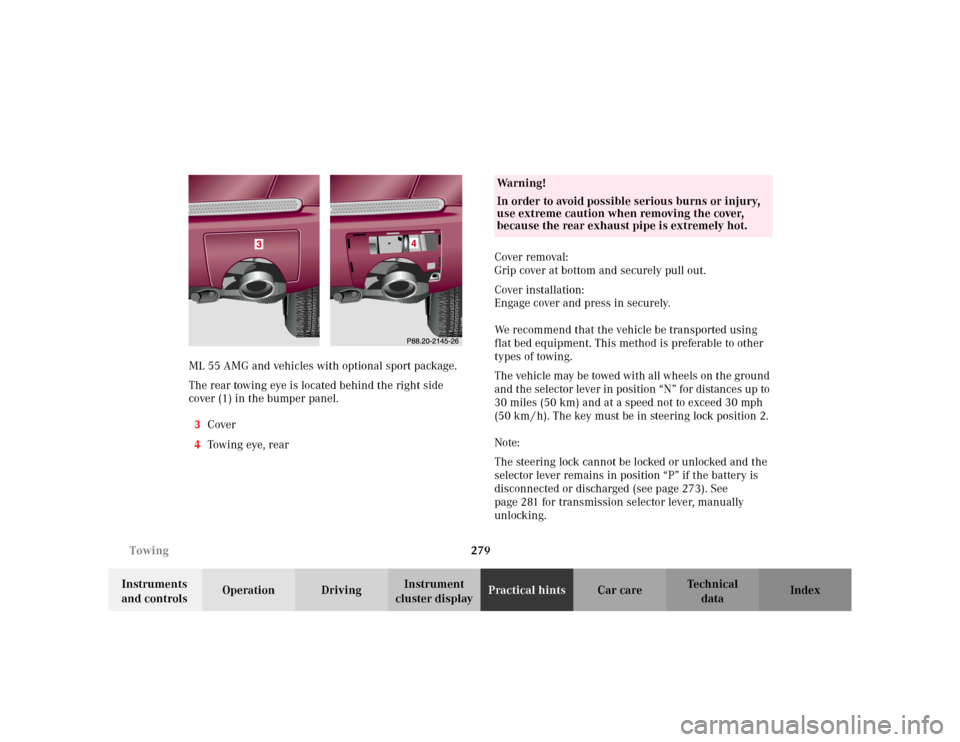
The rear towing eye is located behind the right side
cover (1) in the bumper panel.
3Cover
4Tow i n g eye , r e a rCover removal:
Grip cover at bottom and securely pull out.
Cover installation:
Engage cover and press in securely.
We recommend that the vehicle be transported using
flat bed equipment. This method is preferable to other
types of towing.
The vehicle may be towed with all wheels on the ground
and the selector lever in position “N” for distances up to
30 miles (50 km) and at a speed not to exceed 30 mph
(50 km / h). The key must be in steering lock position 2.
Note:
The steering lock cannot be locked or unlocked and the
selector lever remains in position “P” if the battery is
disconnected or discharged (see page 273). See
page 281 for transmission selector lever, manually
unlocking.
Wa r n i n g !
In order to avoid possible serious burns or injury,
use extreme caution when removing the cover,
because the rear exhaust pipe is extremely hot.