engine oil MERCEDES-BENZ ML500 1997 Complete Manual Online
[x] Cancel search | Manufacturer: MERCEDES-BENZ, Model Year: 1997, Model line: ML500, Model: MERCEDES-BENZ ML500 1997Pages: 4133, PDF Size: 88.89 MB
Page 1132 of 4133

328 IndexK
Key
Global locking 89
Global unlocking 89
Loss of 90
Positions in steering lock 33
Remote control with folding key 88
Unlocking liftgate 89
Unlocking the driver’s door, fuel filler
flap 89
Key positions in steering lock 33
Key, Mechanical 261
Key, Remote control
Unlocking with 32
Kickdown 123, 313
L
Labels, identification 292
Lamp bulbs, exterior 266
Lamps, exterior
Front 266
Rear 267Lamps, indicator and warning
4-ETS 251, 252
ABS 242
Adjustable steering column 253
AIRBAG OFF 63, 243
BAS 78, 245, 246, 247
Battery indicator lamp 254
Brake pad wear 254
Brakes 244
CHECK ENGINE 248
Coolant 249
EBP 245
Engine diagnostics 248
ESP 245, 246, 247, 251
Front fog lamps 253
Fuel reserve 252
Low engine oil level 253
LOW RANGE 252
Low washer system fluid level 253
Seat belts 253
Service indicator 232
SRS 255
Turn signals 25LATCH child seat anchors 72
LATCH child seat mounts 72
Layout of poly-V-belt drive 293
Leather upholstery
Cleaning 239
Lever
For cruise control 150
License plate lamps
Replacing bulbs 267, 271
Liftgate
Closing 92
Opening 89, 91
Opening from inside 91
Opening from outside 91
Light alloy wheels
Cleaning 238
Lighter
Rear center console 169
Lighter see cigarette lighter 168
Page 1133 of 4133

329 Index
Lighting 107
Automatic headlamp mode 108
Cargo compartment 114
Combination switch 110
Daytime running lamp mode 109
Door entry lamps 113
Front fog lamps 111
High beam flasher 110
High beams 110
Instrument cluster illumination 116
Interior 112
Locator lighting 110
Night security illumination 109
Limiting the gear range 121
Limp Home Mode 124
Line of fall 313
Loading 157
Cargo area cover blind* 161
Cargo floor plates 162
Cargo tie-down rings 158
Hooks 159
Instructions 157, 158
Partition net* 159
Roof rack 163Split rear bench seat 99
Trailer 208
Locator lighting 110
Lock button 313
Locking 88
Automatic while driving 93
Centrally from inside 94
Fuel filler flap 214
Global 89
Vehicle in an emergency 262
Locking knobs 32
Loss of keys 90
Loss of Service and Warranty Information
Booklet 291
Low beam headlamps
Replacing bulbs 266, 268
Switching on 48
Low engine oil level
Indicator lamp 253
LOW RANGE - 4-ETS 80
LOW RANGE - ABS 77LOW RANGE - ESP 81
LOW RANGE mode 125
Low washer system fluid level
Indicator lamp 253
Lowering
Vehicle 276
M
Main dimensions 298
Maintenance 12
Display messages 256
Manual operations
Fuel filler flap 263
Interior lighting control 113
Locking the vehicle 262
Sliding/pop-up roof* 265
Unlocking the driver’s door 261
Unlocking transmission selector
lever 264
Page 1141 of 4133

337 Index
Sun visor 132
Supplemental Restraint System
(SRS) 314
Switching off
Automatic climate control 137
ESP 81
Hazard warning flasher 112
Headlamps 54
Rapid seat heating 99
Transmission control – LOW RANGE
mode 125
Switching on
Automatic climate control 137
ESP 82
Front fog lamps 111
Front fog lamps, rear fog lamp 111
Hazard warning flasher 112
Headlamps 48
High beams 110
Rapid seat heating* 98
Seat heating* 98
Transmission control – LOW RANGE
mode 125
Trip computer* 186
Windshield wipers 49Synchronizing
ESP 246
Power windows 146
Remote control 263
Sliding/pop-up roof* 149
T
Tachometer 26, 118
Displaying gear range 121
Tail lamps 270
Cleaning 236
Replacing bulbs 267Tar stains 235
Technical data 302
Brake fluid 302
Coolants 304
Electrical system 297
Engine 294
Engine oil 302
Engine oil additives 302
Fuel requirements 303
Gasoline additives 303
Main dimensions 298
Premium unleaded gasoline 303
Rims and tires 295
Weights 299
Windshield and headlamp washer
system 307
Tele Aid System* 315
Page 1170 of 4133
1998-03 AUTOMATIC TRANSMISSIONS
Complete Transmissions - ML 320 - 722.662
MODEL IDENTIFICATION
MODEL IDENTIFICATION
COMPLETE TRANSMISSION
REMOVE/INSTALL OIL PUMP
Model (Year)ChassisEngineTransmission
ML320 (2001-03)163.154112.942722.662
2001 Mercedes-Benz ML320
1998-03 AUTOMATIC TRANSMISSIONS Complete Transmissions - ML 320 - 722.662
2001 Mercedes-Benz ML320
1998-03 AUTOMATIC TRANSMISSIONS Complete Transmissions - ML 320 - 722.662
me
Saturday, October 02, 2010 3:15:25 PMPage 1 © 2006 Mitchell Repair Information Company, LLC.
me
Saturday, October 02, 2010 3:15:33 PMPage 1 © 2006 Mitchell Repair Information Company, LLC.
Page 1202 of 4133
The parking lock gear and drive flange are connected to the output shaft by gearing.
Freewheels F1 and F2 optimize shifting. The front freewheel (F1) rests against the stator shaft extension on the
transmission side and connects the sun gear of the front planetary gear set tot the transmission housing in the
locking direction.
The torque converter housing and transmission housing are made of a metal alloy. They are bolted together and
centered via the outer multiple-disc carrier of the multiple-disc brake B1. A coated intermediate panel seals the
two components.
The oil pump and outer multiple-disc carrier of the front multiple-disc brake are bolted to the converter housing.
The mechanical part consists of the propeller shaft, output shaft, a sun gear shaft and three planetary gearsets
which are coupled together.
In transmissions for powerful engines, the planetary gearsets have 4 planetary gears, while for less powerful
engines the front and rear planetary gear system has three planetary gear wheels. The stator shaft is pressed into
this and is secured against turning by a spline.
The rear freewheel (F2) connects the sun gear of the center planetary gear set to the sun gear of the rear
planetary gearset in the locking direction.
The electrohydraulic control unit consists of the shift plate made of light alloy for hydraulic control and an
electronic control unit.
The electrical control unit consists of a supporting body made of plastic in which the electrical components are
combined. The shell is screwed tot he shift plate. Conductor tracks which are integrated into the shell, connect
the electric components to a plug connector. This 13-pin plug connector forms the connection with the vehicle-
side wiring harness and with the ETC 5 (Electronic Transmission Control) control module (N15/5) via a
bayonet lock.
Automatic Transmission, Location Of Mechanical Parts
See AUTOMATIC TRANSMISSION, LOCATION OF MECHANICAL PARTS
.
Automatic Transmission, Location Of Electric/Electronic Components
See AUTOMATIC TRANSMISSION, LOCATION OF ELECTRIC/ELECTRONIC
COMPONENTS.
Automatic Transmission, Location Of Hydraulic Components
See AUTOMATIC TRANSMISSION, POSITION OF HYDRAULIC COMPONENTS
.
Automatic Transmission, Location Of Components, Floor Shift
See AUTOMATIC TRANSMISSION, LOCATION OF COMPONENTS, FLOOR SHIFT
.
2001 Mercedes-Benz ML320
1998-03 AUTOMATIC TRANSMISSIONS Complete Transmissions - ML 320 - 722.662
me
Saturday, October 02, 2010 3:15:26 PMPage 33 © 2006 Mitchell Repair Information Company, LLC.
Page 1232 of 4133
vehicle is stationary and the engine is idling, boosts the engine torque and provides infinitely variable
engine speed and torque matching when moving off.
Torque Converter, Design
The impeller (P) is connected to the engine, the turbine wheel (T) is connected to the transmission input
shaft.
The stator (L) is connected to the transmission housing via a freewheel and the stator shaft (8).
Torque Converter, Function
See TORQUE CONVERTER, FUNCTION
.
Torque Converter, Function
Due to the effect of centrifugal force, the blades of the impeller (P) pump the oil outwards to the turbine wheel
(T), causing it to rotate. See Fig. 31
. The turbine wheel blades direct the oil onto the blades of the stator, which
in turn push the oil back to the impeller (P) (arrow). This diversion at the stator (L), which is supported against
the transmission housing via the freewheel, produces and increase in torque. At the maximum speed difference
between the impeller and the turbine wheel (T), the torque conversion achieves its maximum value at a factor of
1.8 to 2.0, dropping to a torque ratio of 1:1 as the speeds converge. From this operating state onwards, also
referred to as the coupling point, the stator (l) rotates with the impeller (P) and the turbine wheel (T).
Efficiencies of up to approximately 98% are achieved in the coupling range.
The oil in the torque converter is constantly being replaced so that the heat produced in the operating phase can
be dissipated via the transmission oil cooler.
2001 Mercedes-Benz ML320
1998-03 AUTOMATIC TRANSMISSIONS Complete Transmissions - ML 320 - 722.662
me
Saturday, October 02, 2010 3:15:26 PMPage 63 © 2006 Mitchell Repair Information Company, LLC.
Page 1264 of 4133
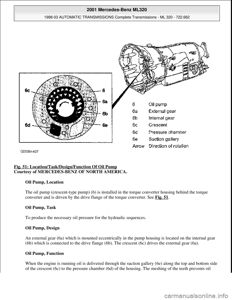
Fig. 51: Location/Task/Desi gn/Function Of Oil Pump
Courtesy of MERCEDES-BENZ OF NORTH AMERICA.
Oil Pump, Location
The oil pump (crescent-type pump) (6) is installed in the torque converter housing behind the torque
converter and is driven by the drive flange of the torque converter. See Fig. 51
.
Oil Pump, Task
To produce the necessary oil pressure for the hydraulic sequences.
Oil Pump, Design
An external gear (6a) which is m ounted eccentrically in the pump housi ng is located on the internal gear
(6b) which is connected to the drive flange (6b). The crescent (6c) drives the external gear (6a).
Oil Pump, Function
When the engine is running oil is delivered through th e suction gallery (6e) along the top and bottom side
of the crescent (6c) to the pr essure chamber (6d) of the housin
g. The meshing of the teeth prevents oil
2001 Mercedes-Benz ML320
1998-03 AUTOMATIC TRANSMI SSIONS Complete Transmissions - ML 320 - 722.662
me
Saturday, October 02, 2010 3:15:26 PMPage 95 © 2006 Mitchell Repair Information Company, LLC.
Page 1333 of 4133
Task - The ETC control module (N15/3) determines the instantaneous operating condition of the vehicle and
controls all gearshift sequences taking into account the ease of shifting and the driving situation. This involves
receiving, converting and transmitting various digital and analog signals. See Fig. 96
.
It receives operating data in the form of input signals from:
Starter Lock-Out Contact (Y3/6S1)
RPM Sensor 2 (Y3/6N2)
RPM Sensor 3 (Y3/6n3)
Transmission Oil Temperature Sensor (Y3/6B1)
In addition there is a connection via the engine compartment bus to the:
Instrument Cluster (A1)
ME-SFI Control Module (N3/10) or CDI Control Module (N3/9)
The solenoid valves for the modulating and shift pressure and for the gear changes are actuated by the ETC
control module (N15/3).
The pressure required is calculated from all input signals, adjusted to the torque to be transferred. The following
information from other systems is then processed.
ME-SFI Control Module (N3/10) or CDI Control Module (N3/9):
Engine Torque
Engine Speed
Accelerator Pedal Position
Gear Shift
Engine Status
Electronic Selector Lever Module Control Module (N15/5):
Kickdown Switch (S16/6)
Selector Lever Position P/N
Traction System Control Module (N47):
Transmission Ratio
Speeds
Instrument Cluster (A1):
Selector Lever Position/Shift Range
2001 Mercedes-Benz ML320
1998-03 AUTOMATIC TRANSMISSIONS Complete Transmissions - ML 320 - 722.662
me
Saturday, October 02, 2010 3:15:27 PMPage 164 © 2006 Mitchell Repair Information Company, LLC.
Page 1335 of 4133
Courtesy of MERCEDES-BENZ OF NORTH AMERICA.
Task - The ETC control module (N15/3) determines the instantaneous operating condition for the vehicle and
controls all gearshift sequences taking into account the ease of shifting and the driving situation. See Fig. 97
.
This involves receiving , converting and transmitting various digital and analog signals.
Input signals:
Starter Lock-Out Contact (Y3/6S1)
RPM Sensor 2 (Y3/6N2)
RPM Sensor 3 (Y3/6N3)
Transmission Oil Temperature Sensor (Y3/6B1)
Kickdown Switch (S16/6)
Gear Recognition Switch (S16/10)
Output signals:
Reverse/parking lock valve
Input and output signals:
Datalink connector (X11/4)
In addition there is a connection via the engine compartment bus to the:
ME-SFI Control Module (N3/10) or CDI Control Module (N3/9)
Traction System Control Module (N47)
Transfer Case Control Module (N78)
The solenoid valves for the modulating and shift pressure and for the gear changes are actuated by the ETC
control module (N15/3). The pressure required is calculated from all input signals, adjusted to the torque to be
transferred.
The following information from other systems is then processed:
ME-SFI Control Module (N3/10) or CDI Control Module (N3/9)
(Y66/1)
Selector lever position P/N to the engine control module (ME-SFI) (N3/10) (only on detection of the
selector lever position "P" or "N" on the transmission range recognition switch (S16/10) and at the starter
interlock contact (Y3/6s1)).
Traction system control module (N47):
Wheel speeds
2001 Mercedes-Benz ML320
1998-03 AUTOMATIC TRANSMISSIONS Complete Transmissions - ML 320 - 722.662
me
Saturday, October 02, 2010 3:15:27 PMPage 166 © 2006 Mitchell Repair Information Company, LLC.
Page 1352 of 4133
Fig. 106: Torque Converter Lockup Clutch, Function
Courtesy of MERCEDES-BENZ OF NORTH AMERICA.
Operation
When actuated by the ETC control module (N15/3), oil pressure controlled by the torque converter lockup
PWM solenoid Valve (Y3/6y6) is directed through the input shaft (1) to the pressure chamber behind the piston
(16d). See Fig. 106
. The piston presses the clutch pack (16c) together and allows torque to be transferred
directly between the impeller (P) and turbine wheel (T). The torque converter lockup clutch is activated in 5th,
4th and 3rd gears in relation to the engine speed and engine load.
AUTOMATIC TRANSMISSION, FUNCTION
Transmission without touch shift. 722.6 in MODEL 163, 170, 202, 208, 210.
Transmission 722.6 in MODEL 129, 140.
Automatic transmission 722.6 is an electronically controlled 5-speed transmission with a lockup clutch in the
torque converter.
The ratios for the gear stages are achieved by three planetary gear sets. The 5th gear is designed with a step-up
ratio as an overdrive.
Shifting is initiated electronically. The gears are shifted by the corresponding combination of three
hydraulically actuated multi-plate brakes, three hydraulically actuated multi-disc clutches and two mechanical
freewheels.
Basically automatic transmission 722.6 with electronic control offers the following advantages:
Reduced fuel consumption
Improved shift comfort
More favorable gear steps as a result of 5 gears
Enhanced life and reliability
Reduced servicing costs
The electrohydraulic control unit is bolted onto the bottom of the transmission housing. The end of the
transmission is formed by an oil pan made of sheet steel.
The oil pressure for the converter lockup clutch and center multiple disc clutch is supplied via holes in the input
shaft. The oil pressure to the rear multiple-disc clutch is routed through the output shaft. The lubricating oil is
supplied and distributed by additional bore holes in both shafts. All bearing points of the gear sets as well as
freewheels and shift elements are supplied with lubricating oil.
The parking lock gear and drive flange are connected to the output shaft by gearing.
Freewheels F1 and F2 optimize shiftin
g. The front freewheel (F1) rests against the stator shaft extension on the
2001 Mercedes-Benz ML320
1998-03 AUTOMATIC TRANSMISSIONS Complete Transmissions - ML 320 - 722.662
me
Saturday, October 02, 2010 3:15:28 PMPage 183 © 2006 Mitchell Repair Information Company, LLC.