weight MERCEDES-BENZ ML550 2010 W164 Owner's Guide
[x] Cancel search | Manufacturer: MERCEDES-BENZ, Model Year: 2010, Model line: ML550, Model: MERCEDES-BENZ ML550 2010 W164Pages: 368, PDF Size: 9.09 MB
Page 189 of 368
The cargo compartment is the preferred place
to carry objects. Always use cargo tie-down
rings, and if so equipped, always use the cargo
net when transporting cargo.
Never drive a vehicle with the tailgate open.
Deadly carbon monoxide (CO) gases may
enter vehicle interior resulting in
unconsciousness and death.
Load distribution
The Gross Vehicle Weight (GVW) is the weight
of the vehicle including:Rfuel
Rtools
Rspare wheel
Rinstalled accessories
Rpassengers
Rluggage/cargo
It must never exceed the load limit and the
Gross Vehicle Weight Rating (GVWR) for your
vehicle. The load limit and the GVWR are
specified on the placard located on the
driver’s door B-pillar (Y page 227).
In addition, the load must be distributed so
that the weight on each axle never exceeds
the Gross Axle Weight Rating (GAWR) for the
front and rear axle. The GVWR and GAWR for
your vehicle are indicated on the certification
label located on the driver’s door B-pillar
(Y page 227).
For more information, see “Tire and Loading
Information” (Y page 227).
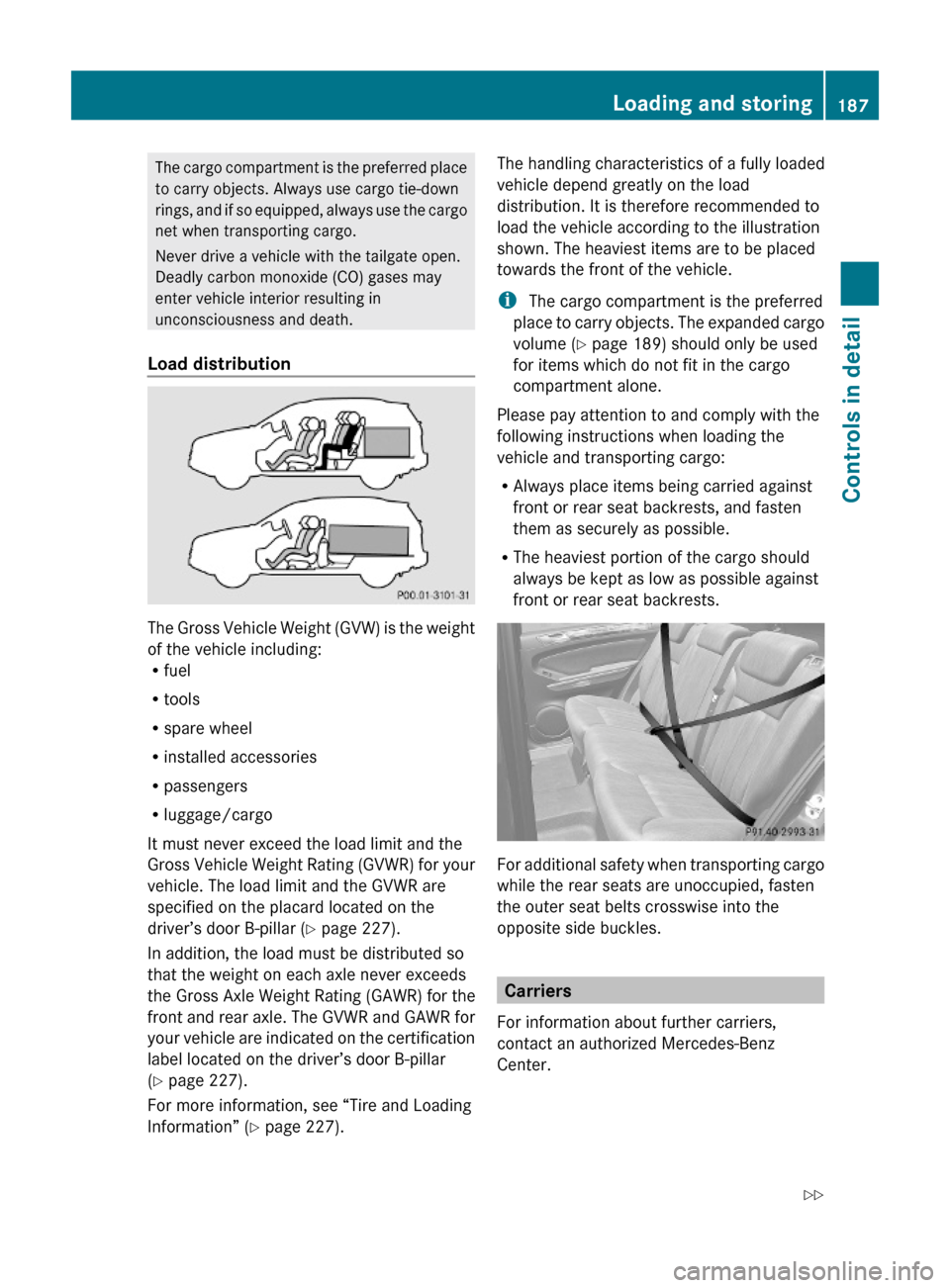
The handling characteristics of a fully loaded
vehicle depend greatly on the load
distribution. It is therefore recommended to
load the vehicle according to the illustration
shown. The heaviest items are to be placed
towards the front of the vehicle.
i The cargo compartment is the preferred
place to carry objects. The expanded cargo
volume (Y page 189) should only be used
for items which do not fit in the cargo
compartment alone.
Please pay attention to and comply with the
following instructions when loading the
vehicle and transporting cargo:
RAlways place items being carried against
front or rear seat backrests, and fasten
them as securely as possible.
RThe heaviest portion of the cargo should
always be kept as low as possible against
front or rear seat backrests.
For additional safety when transporting cargo
while the rear seats are unoccupied, fasten
the outer seat belts crosswise into the
opposite side buckles.
Carriers
For information about further carriers,
contact an authorized Mercedes-Benz
Center.
Loading and storing187Controls in detail164_AKB; 7; 31, en-USd2ureepe,Version: 2.11.8.12009-09-11T12:07:36+02:00 - Seite 187Z
Page 190 of 368
GWarning!
Only use carriers when the basic carrier bars
have been completely mounted. The left and
right roof rails are only stabilized by means of
the basic carrier bars mounted.
Follow the manufacturer’s installation
instructions. Otherwise, an improperly
attached carrier or its load could become
detached from the vehicle.
Do not exceed the maximum roof load of
220 lb (100 kg).
Take into consideration that when the roof is
loaded, the handling characteristics are
different from those when operating the
vehicle without the roof loaded.
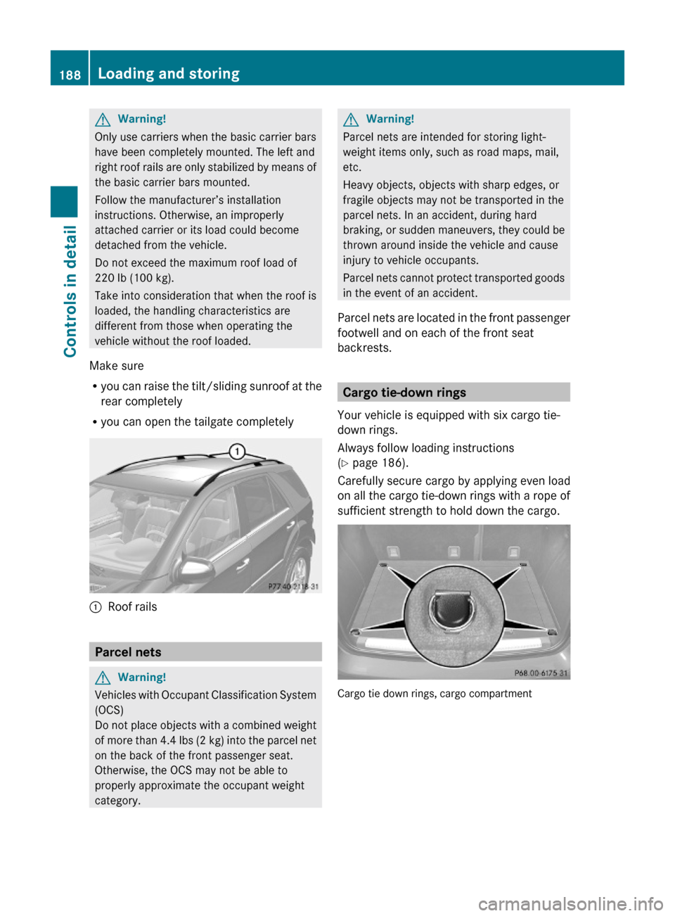
Make sure
Ryou can raise the tilt/sliding sunroof at the
rear completely
Ryou can open the tailgate completely
:Roof rails
Parcel nets
GWarning!
Vehicles with Occupant Classification System
(OCS)
Do not place objects with a combined weight
of more than 4.4 lbs (2 kg) into the parcel net
on the back of the front passenger seat.
Otherwise, the OCS may not be able to
properly approximate the occupant weight
category.
GWarning!
Parcel nets are intended for storing light-
weight items only, such as road maps, mail,
etc.
Heavy objects, objects with sharp edges, or
fragile objects may not be transported in the
parcel nets. In an accident, during hard
braking, or sudden maneuvers, they could be
thrown around inside the vehicle and cause
injury to vehicle occupants.
Parcel nets cannot protect transported goods
in the event of an accident.
Parcel nets are located in the front passenger
footwell and on each of the front seat
backrests.
Cargo tie-down rings
Your vehicle is equipped with six cargo tie-
down rings.
Always follow loading instructions
(Y page 186).
Carefully secure cargo by applying even load
on all the cargo tie-down rings with a rope of
sufficient strength to hold down the cargo.
Cargo tie down rings, cargo compartment
188Loading and storingControls in detail
164_AKB; 7; 31, en-USd2ureepe,Version: 2.11.8.12009-09-11T12:07:36+02:00 - Seite 188
Page 191 of 368
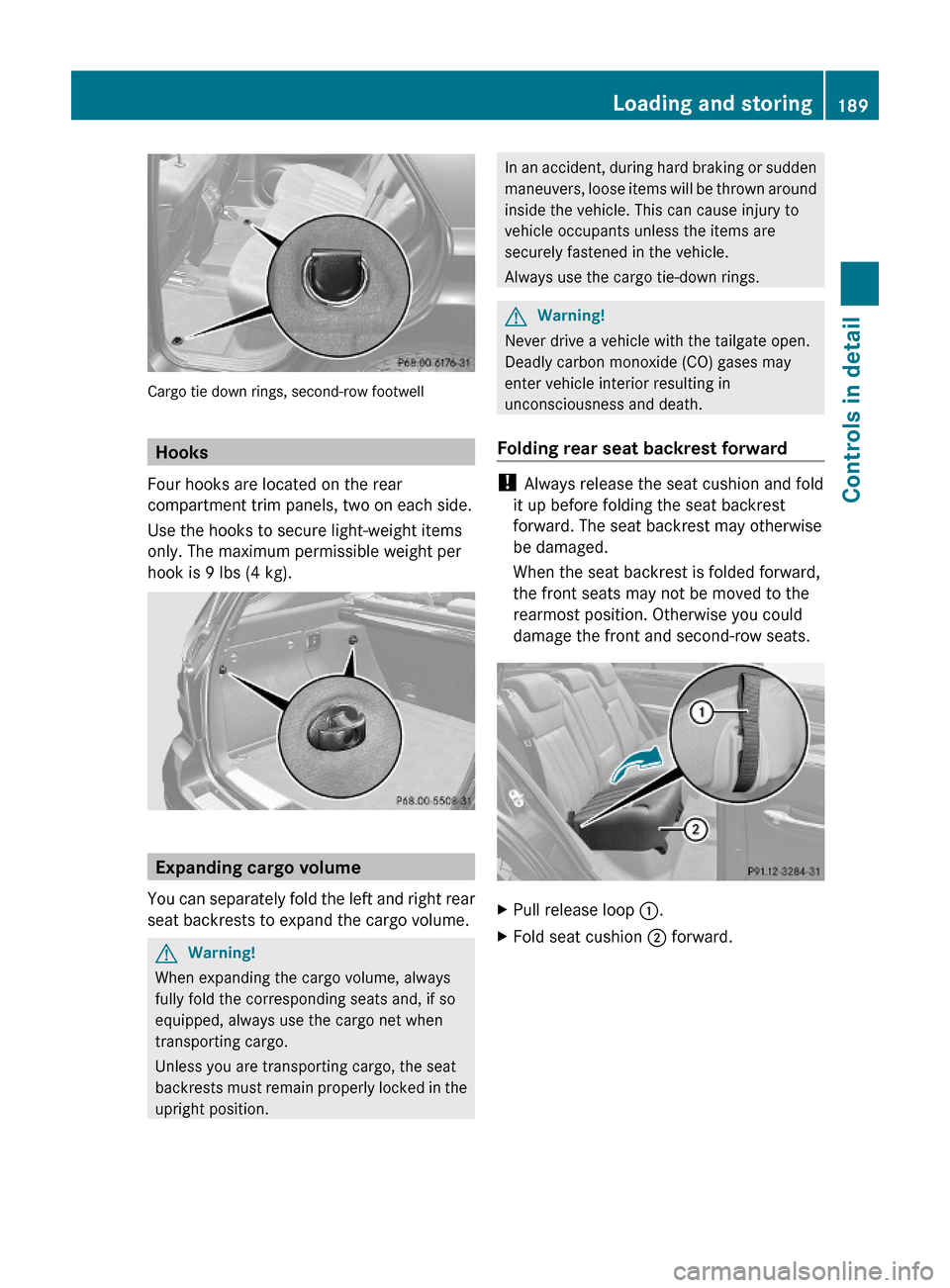
Cargo tie down rings, second-row footwell
Hooks
Four hooks are located on the rear
compartment trim panels, two on each side.
Use the hooks to secure light-weight items
only. The maximum permissible weight per
hook is 9 lbs (4 kg).
Expanding cargo volume
You can separately fold the left and right rear
seat backrests to expand the cargo volume.
GWarning!
When expanding the cargo volume, always
fully fold the corresponding seats and, if so
equipped, always use the cargo net when
transporting cargo.
Unless you are transporting cargo, the seat
backrests must remain properly locked in the
upright position.
In an accident, during hard braking or sudden
maneuvers, loose items will be thrown around
inside the vehicle. This can cause injury to
vehicle occupants unless the items are
securely fastened in the vehicle.
Always use the cargo tie-down rings.
GWarning!
Never drive a vehicle with the tailgate open.
Deadly carbon monoxide (CO) gases may
enter vehicle interior resulting in
unconsciousness and death.
Folding rear seat backrest forward
! Always release the seat cushion and fold
it up before folding the seat backrest
forward. The seat backrest may otherwise
be damaged.
When the seat backrest is folded forward,
the front seats may not be moved to the
rearmost position. Otherwise you could
damage the front and second-row seats.
XPull release loop :.XFold seat cushion ; forward.Loading and storing189Controls in detail164_AKB; 7; 31, en-USd2ureepe,Version: 2.11.8.12009-09-11T12:07:36+02:00 - Seite 189Z
Page 197 of 368
XRemoving: Hold cup holder at its
bridge ; and pull out bridge in direction of
arrow.
XPull cup holder : out in direction of arrow.XReinstalling: First, insert cup holder :
and then insert bridge ;.
Cup holder in rear armrest
XFold down the rear armrest.
! Do not sit on or lean your body weight
against the armrest when it is folded down,
as you could otherwise damage it.
Sun visors
GWarning!
Do not use the vanity mirror while driving.
Keep the vanity mirrors in the sun visors
closed while vehicle is in motion. Reflected
glare can endanger you and others.
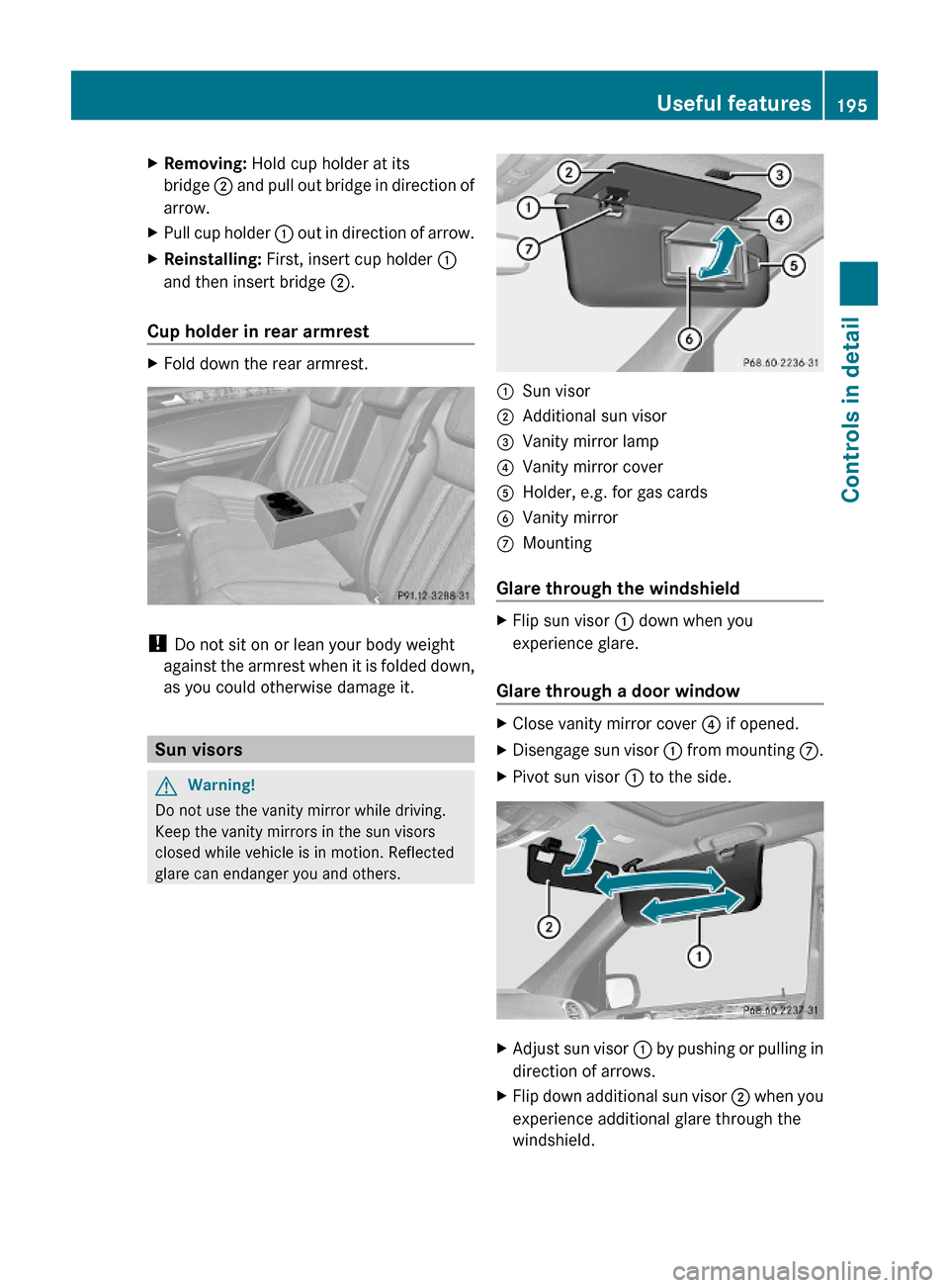
:Sun visor;Additional sun visor=Vanity mirror lamp?Vanity mirror coverAHolder, e.g. for gas cardsBVanity mirrorCMounting
Glare through the windshield
XFlip sun visor : down when you
experience glare.
Glare through a door window
XClose vanity mirror cover ? if opened.XDisengage sun visor : from mounting C.XPivot sun visor : to the side.XAdjust sun visor : by pushing or pulling in
direction of arrows.
XFlip down additional sun visor ; when you
experience additional glare through the
windshield.
Useful features195Controls in detail164_AKB; 7; 31, en-USd2ureepe,Version: 2.11.8.12009-09-11T12:07:36+02:00 - Seite 195Z
Page 222 of 368
pressures : for maximum loaded vehicle
weight. The tire inflation pressures listed
apply to the tires installed as original
equipment.
Important notes on tire inflation
pressure
GWarning!
If the tire inflation pressure drops repeatedly,
check the tires for punctures from foreign
objects and/or whether air is leaking from the
valves or from around the rim.
Tire temperature and tire inflation pressure
are also increased while driving, depending
on the driving speed and the tire load.
If you will be driving your vehicle at high
speeds of 100 mph (160 km/h) or higher,
where it is legal and conditions allow, consult
the tire inflation pressure label on the inside
of the fuel filler flap on how to adjust the cold
tire inflation pressure. If you do not adjust the
tire inflation pressure, excessive heat can
build up and result in sudden tire failure.
If you are not sure about the proper tire
inflation pressure, contact an authorized
Mercedes-Benz Center.
iDriving comfort may be reduced when the
tire inflation pressure is adjusted to the
value for speeds above 100 mph
(160 km/h) as specified on the tire inflation
pressure label located on the inside of the
fuel filler flap.
Make sure to readjust the tire inflation
pressure for normal driving speeds.
Supplemental tire inflation pressure
information for different loading conditions of
the vehicle can be found on the tire inflation
pressure label. The tire inflation pressure
label is located on the inside of the fuel filler
flap.
For the tire inflation pressure for spare
wheels such as Minispare wheels or spare
wheels with collapsible tire refer to
Rthe yellow label on the spare wheel rim
Rthe “Technical data” section of this
Operator’s Manual (Y page 356)
Rthe Tire and Loading Information placard on
the driver’s door B-pillar
Unless specified otherwise, the tire inflation
pressures on the tire inflation pressure label
are valid for all approved, factory-equipped
tires.
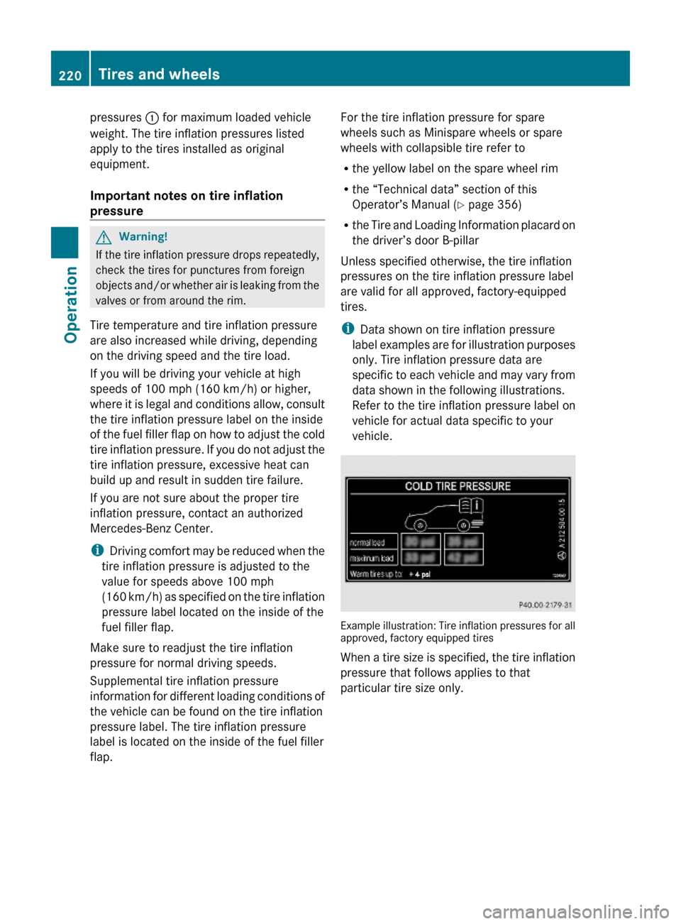
iData shown on tire inflation pressure
label examples are for illustration purposes
only. Tire inflation pressure data are
specific to each vehicle and may vary from
data shown in the following illustrations.
Refer to the tire inflation pressure label on
vehicle for actual data specific to your
vehicle.
Example illustration: Tire inflation pressures for allapproved, factory equipped tires
When a tire size is specified, the tire inflation
pressure that follows applies to that
particular tire size only.
220Tires and wheelsOperation
164_AKB; 7; 31, en-USd2ureepe,Version: 2.11.8.12009-09-11T12:07:36+02:00 - Seite 220
Page 229 of 368
punctured or damaged by road debris,
potholes etc.
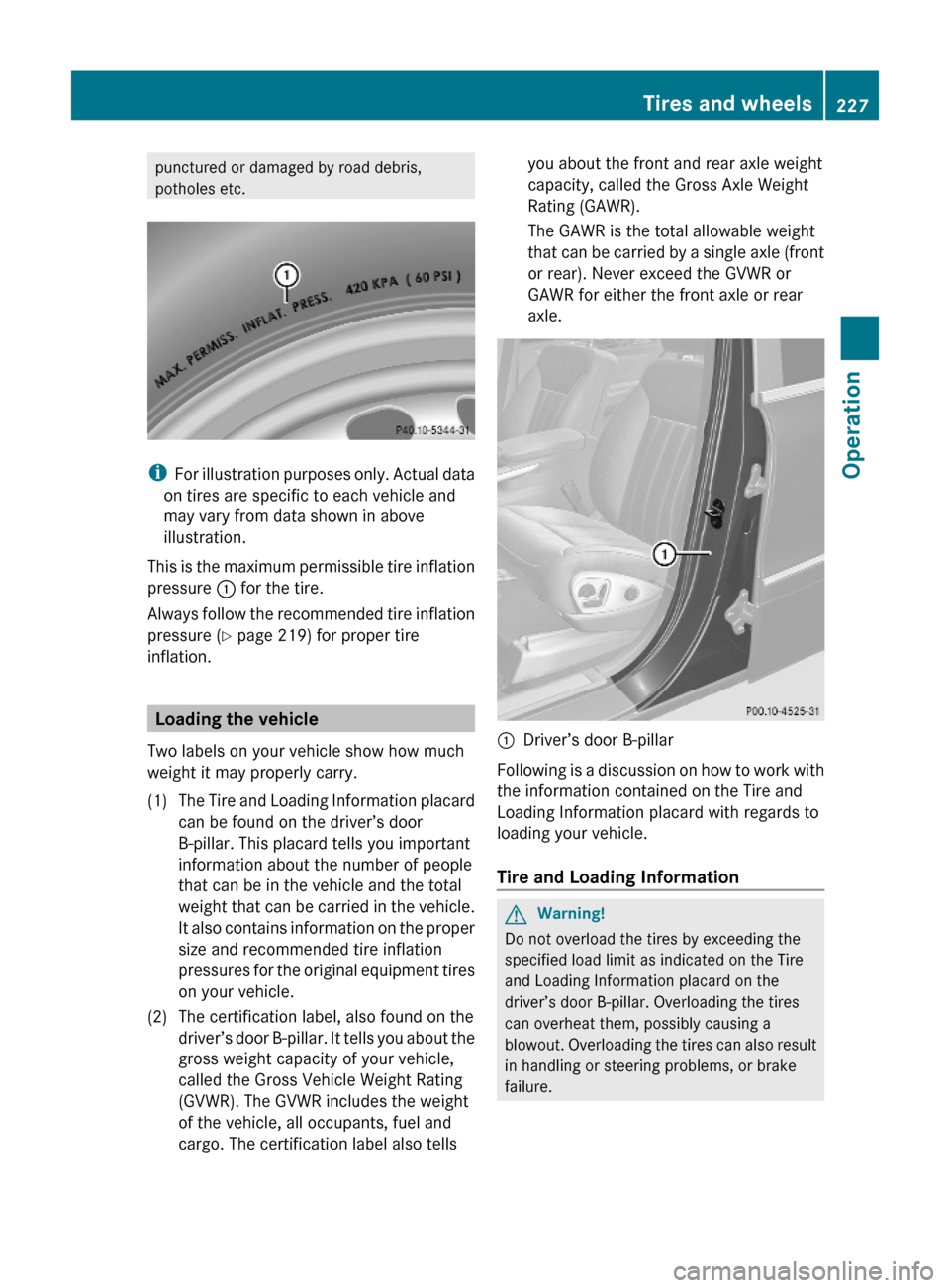
iFor illustration purposes only. Actual data
on tires are specific to each vehicle and
may vary from data shown in above
illustration.
This is the maximum permissible tire inflation
pressure : for the tire.
Always follow the recommended tire inflation
pressure (Y page 219) for proper tire
inflation.
Loading the vehicle
Two labels on your vehicle show how much
weight it may properly carry.
(1)The Tire and Loading Information placard
can be found on the driver’s door
B-pillar. This placard tells you important
information about the number of people
that can be in the vehicle and the total
weight that can be carried in the vehicle.
It also contains information on the proper
size and recommended tire inflation
pressures for the original equipment tires
on your vehicle.
(2)The certification label, also found on the
driver’s door B-pillar. It tells you about the
gross weight capacity of your vehicle,
called the Gross Vehicle Weight Rating
(GVWR). The GVWR includes the weight
of the vehicle, all occupants, fuel and
cargo. The certification label also tells
you about the front and rear axle weight
capacity, called the Gross Axle Weight
Rating (GAWR).
The GAWR is the total allowable weight
that can be carried by a single axle (front
or rear). Never exceed the GVWR or
GAWR for either the front axle or rear
axle.
:Driver’s door B-pillar
Following is a discussion on how to work with
the information contained on the Tire and
Loading Information placard with regards to
loading your vehicle.
Tire and Loading Information
GWarning!
Do not overload the tires by exceeding the
specified load limit as indicated on the Tire
and Loading Information placard on the
driver’s door B-pillar. Overloading the tires
can overheat them, possibly causing a
blowout. Overloading the tires can also result
in handling or steering problems, or brake
failure.
Tires and wheels227Operation164_AKB; 7; 31, en-USd2ureepe,Version: 2.11.8.12009-09-11T12:07:36+02:00 - Seite 227Z
Page 230 of 368
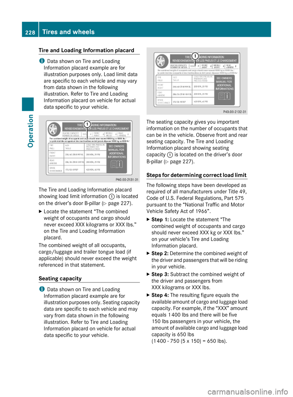
Tire and Loading Information placard
iData shown on Tire and Loading
Information placard example are for
illustration purposes only. Load limit data
are specific to each vehicle and may vary
from data shown in the following
illustration. Refer to Tire and Loading
Information placard on vehicle for actual
data specific to your vehicle.
The Tire and Loading Information placard
showing load limit information : is located
on the driver’s door B-pillar (Y page 227).
XLocate the statement “The combined
weight of occupants and cargo should
never exceed XXX kilograms or XXX lbs.”
on the Tire and Loading Information
placard.
The combined weight of all occupants,
cargo/luggage and trailer tongue load (if
applicable) should never exceed the weight
referenced in that statement.
Seating capacity
iData shown on Tire and Loading
Information placard example are for
illustration purposes only. Seating capacity
data are specific to each vehicle and may
vary from data shown in the following
illustration. Refer to Tire and Loading
Information placard on vehicle for actual
data specific to your vehicle.
The seating capacity gives you important
information on the number of occupants that
can be in the vehicle. Observe front and rear
seating capacity. The Tire and Loading
Information placard showing seating
capacity : is located on the driver’s door
B-pillar (Y page 227).
Steps for determining correct load limit
The following steps have been developed as
required of all manufacturers under Title 49,
Code of U.S. Federal Regulations, Part 575
pursuant to the “National Traffic and Motor
Vehicle Safety Act of 1966”.
XStep 1: Locate the statement “The
combined weight of occupants and cargo
should never exceed XXX kg or XXX lbs.”
on your vehicle’s Tire and Loading
Information placard.
XStep 2: Determine the combined weight of
the driver and passengers that will be riding
in your vehicle.
XStep 3: Subtract the combined weight of
the driver and passengers from
XXX kilograms or XXX lbs.
XStep 4: The resulting figure equals the
available amount of cargo and luggage load
capacity. For example, if the “XXX” amount
equals 1 400 lbs and there will be five
150 lbs passengers in your vehicle, the
amount of available cargo and luggage load
capacity is 650 lbs
(1 400 - 750 (5 x 150) = 650 lbs).
228Tires and wheelsOperation
164_AKB; 7; 31, en-USd2ureepe,Version: 2.11.8.12009-09-11T12:07:36+02:00 - Seite 228
Page 231 of 368
XStep 5: Determine the combined weight of
luggage and cargo being loaded on the
vehicle. That weight may not safely exceed
the available cargo and luggage load
capacity calculated in step 4.XStep 6 (if applicable): If your vehicle will
be towing a trailer, load from your trailer
will be transferred to your vehicle. Consult
this manual to determine how this reduces
the available cargo and luggage load
capacity of your vehicle ( Y page 231).
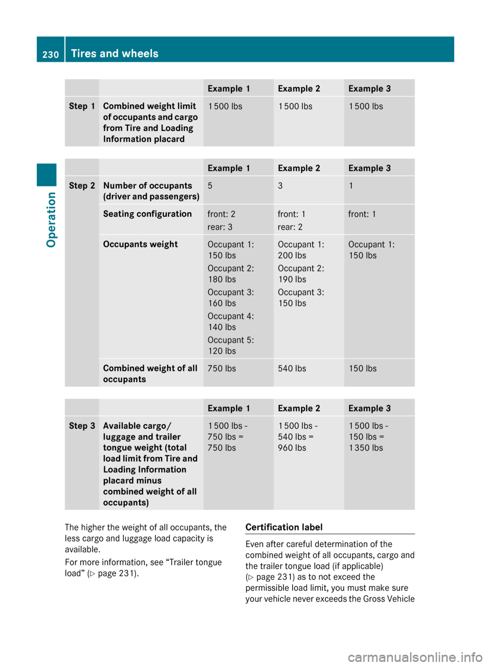
The following table shows examples on how
to calculate total and cargo load capacities
with varying seating configurations and
number and size of occupants. The following
examples use a load limit of 1 500 lbs. This
is for illustration purposes only. Make sure
you are using the actual load limit for your
vehicle stated on the vehicle’s Tire and
Loading Information placard ( Y page 228).
Tires and wheels229Operation164_AKB; 7; 31, en-USd2ureepe,Version: 2.11.8.12009-09-11T12:07:36+02:00 - Seite 229Z
Page 232 of 368
Example 1Example 2Example 3Step 1Combined weight limit
of occupants and cargo
from Tire and Loading
Information placard1 500 lbs1 500 lbs1 500 lbsExample 1Example 2Example 3Step 2Number of occupants
(driver and passengers)531Seating configurationfront: 2
rear: 3front: 1
rear: 2front: 1Occupants weightOccupant 1:
150 lbs
Occupant 2:
180 lbs
Occupant 3:
160 lbs
Occupant 4:
140 lbs
Occupant 5:
120 lbsOccupant 1:
200 lbs
Occupant 2:
190 lbs
Occupant 3:
150 lbsOccupant 1:
150 lbsCombined weight of all
occupants750 lbs540 lbs150 lbsExample 1Example 2Example 3Step 3Available cargo/
luggage and trailer
tongue weight (total
load limit from Tire and
Loading Information
placard minus
combined weight of all
occupants)1 500 lbs -
750 lbs =
750 lbs1 500 lbs -
540 lbs =
960 lbs1 500 lbs -
150 lbs =
1 350 lbsThe higher the weight of all occupants, the
less cargo and luggage load capacity is
available.
For more information, see “Trailer tongue
load” ( Y page 231).Certification label
Even after careful determination of the
combined weight of all occupants, cargo and
the trailer tongue load (if applicable)
( Y page 231) as to not exceed the
permissible load limit, you must make sure
your vehicle never exceeds the Gross Vehicle
230Tires and wheelsOperation
164_AKB; 7; 31, en-USd2ureepe,Version: 2.11.8.12009-09-11T12:07:36+02:00 - Seite 230
Page 233 of 368
Weight Rating (GVWR) and the Gross Axle
Weight Rating (GAWR) for either the front or
rear axle. You can obtain the GVWR and
GAWR from the certification label. The
certification label can be found on the driver’s
door B-pillar, see the “Technical data” section
(Y page 346).
Gross Vehicle Weight Rating (GVWR): The
total weight of the vehicle, all occupants, all
cargo, and the trailer tongue load (if
applicable) must never exceed the GVWR.
Gross Axle Weight Rating (GAWR): The total
allowable weight that can be carried by a
single axle (front or rear).
To assure that your vehicle does not exceed
the maximum permissible weight limits
(GVWR and GAWR for front and rear axle),
have the loaded vehicle (including driver,
passengers and all cargo and, if applicable,
trailer fully loaded) weighed on a suitable
commercial scale.
Trailer tongue load
The tongue load of any trailer is an important
weight to measure because it affects the load
you can carry in your vehicle. If a trailer is
towed, the tongue load must be added to the
weight of all occupants riding and any cargo
you are carrying in the vehicle. The tongue
load typically is between 8% and 15% of the
trailer weight and everything loaded in it.
Maximum tire load
GWarning!
Do not overload the tires by exceeding the
specified load limit as indicated on the Tire
and Loading Information placard on the
driver’s door B-pillar. Overloading the tires
can overheat them, possibly causing a
blowout. Overloading the tires can also result
in handling or steering problems, or brake
failure.
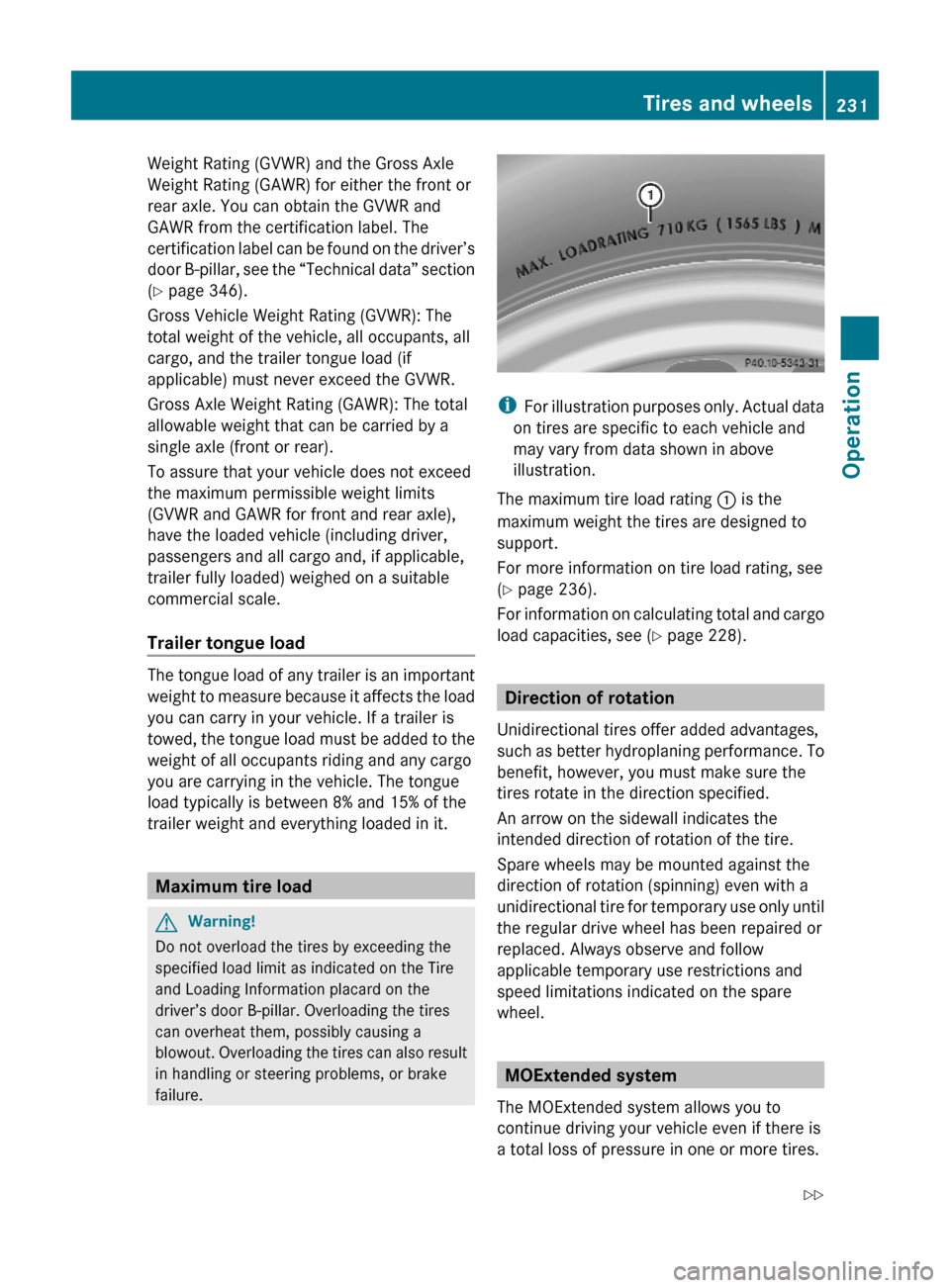
iFor illustration purposes only. Actual data
on tires are specific to each vehicle and
may vary from data shown in above
illustration.
The maximum tire load rating : is the
maximum weight the tires are designed to
support.
For more information on tire load rating, see
(Y page 236).
For information on calculating total and cargo
load capacities, see (Y page 228).
Direction of rotation
Unidirectional tires offer added advantages,
such as better hydroplaning performance. To
benefit, however, you must make sure the
tires rotate in the direction specified.
An arrow on the sidewall indicates the
intended direction of rotation of the tire.
Spare wheels may be mounted against the
direction of rotation (spinning) even with a
unidirectional tire for temporary use only until
the regular drive wheel has been repaired or
replaced. Always observe and follow
applicable temporary use restrictions and
speed limitations indicated on the spare
wheel.
MOExtended system
The MOExtended system allows you to
continue driving your vehicle even if there is
a total loss of pressure in one or more tires.
Tires and wheels231Operation164_AKB; 7; 31, en-USd2ureepe,Version: 2.11.8.12009-09-11T12:07:36+02:00 - Seite 231Z