MERCEDES-BENZ ML55AMG 2001 W163 Owner's Manual
Manufacturer: MERCEDES-BENZ, Model Year: 2001, Model line: ML55AMG, Model: MERCEDES-BENZ ML55AMG 2001 W163Pages: 317, PDF Size: 10.4 MB
Page 241 of 317
238 Spare wheel, vehicle jack
Te ch n ica l
data Instruments
and controlsOperation DrivingInstrument
cluster displayPractical hintsCar care Index
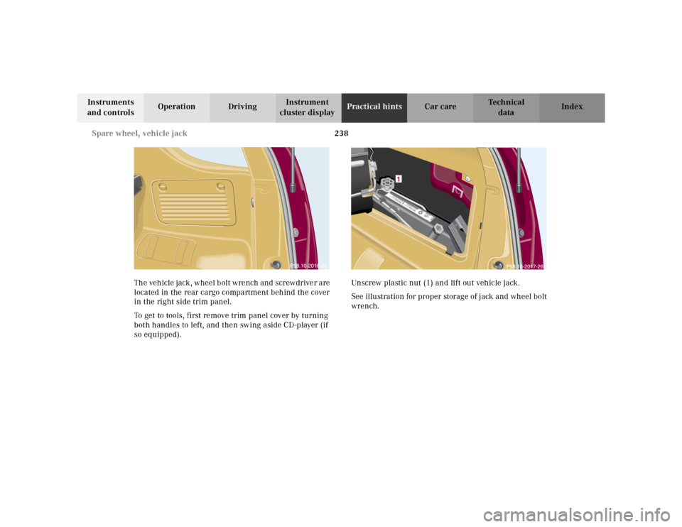
The vehicle jack, wheel bolt wrench and screwdriver are
located in the rear cargo compartment behind the cover
in the right side trim panel.
To get to tools, first remove trim panel cover by turning
both handles to left, and then swing aside CD-player (if
so equipped).Unscrew plastic nut (1) and lift out vehicle jack.
See illustration for proper storage of jack and wheel bolt
wrench.
Warnung!Sich nicht unter
das nur mit dem W
agenheber
aufgebockte Fahrzeug begeben!Warnung!Sich nicht unter
das nur mit dem W
agenheber
aufgebockte Fahrzeug begeben!
Page 242 of 317
239 Spare wheel, vehicle jack
Te ch n ica l
data Instruments
and controlsOperation DrivingInstrument
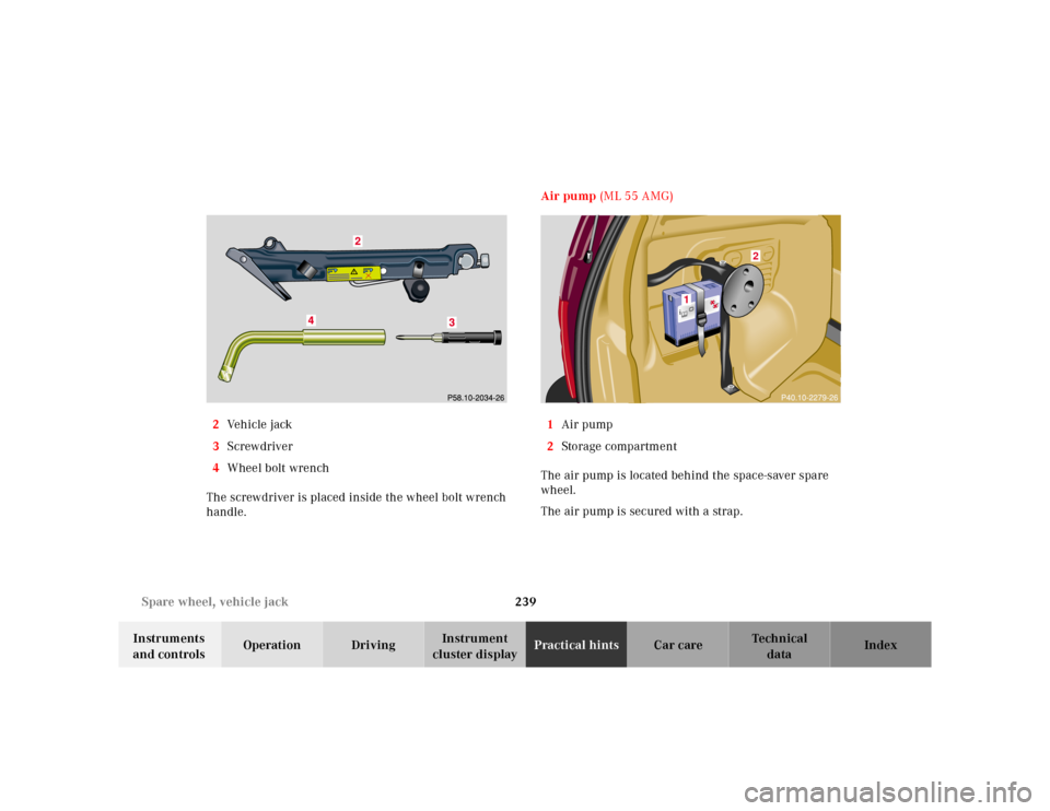
cluster displayPractical hintsCar care Index 2Ve h i c l e j a c k
3Screwdriver
4Wheel bolt wrench
The screwdriver is placed inside the wheel bolt wrench
handle.Air pump (ML 55 AMG)
1Air pump
2Storage compartment
The air pump is located behind the space-saver spare
wheel.
The air pump is secured with a strap.
1
2
Page 243 of 317
240 Tires, Wheels
Te ch n ica l
data Instruments
and controlsOperation DrivingInstrument
cluster displayPractical hintsCar care Index
Wheels
Replace rims or tires with the same designation,
manufacturer and type as shown on the original part.
See your authorized Mercedes-Benz Light Truck Center
for further information.
See your authorized Mercedes-Benz Light Truck Center
for information on tested and recommended rims and
tires for summer and winter operation. They can also
offer advice concerning tire service and purchase.Tire replacement
Front and rear tires should be replaced in sets.
Furthermore – in the event of tire replacement – the
optional regular size spare wheel should be used on the
rear axle. Rims and tires must be of the correct size and
type. For dimensions, see technical data on page 288.
We recommend that you break in new tires for
approximately 60 miles (100 km) at moderate speed.
It is imperative that the wheel mounting bolts be
fastened to a tightening torq ue of 110 ft.lb. (150 Nm)
whenever wheels are mounted.
For rim and tire specifications, refer to technical data on
page 288.
Wa r n i n g !
Do not mix different tire construction types (i.e.
radial, bias, bias-belted) on your vehicle because
handling may be adversely affected and may result
in loss of control.
Wa r n i n g !
Worn, old tires can cause accidents. If the tire tread
is badly worn, or if the tires have sustained
damage, replace them.When replacing rims, use only genuine
Mercedes-Benz wheel bolts specified for the
particular rim type. Failure to do so can result in
the bolts loosening and possibly an accident.
Page 244 of 317
241 Tires, Wheels
Te ch n ica l
data Instruments
and controlsOperation DrivingInstrument
cluster displayPractical hintsCar care Index Rotating wheels
The wheels can be rotated according to the degree of
tire wear while retaining the same direction of travel.
Rotating, however, should be carried out as
recommended by the tire manufacturer, before the
characteristic tire wear pattern (shoulder wear on front
wheels and tread center wear on rear wheels) becomes
visible, as otherwise the driving properties deteriorate.
Important!
Unidirectional tires must always be mounted with arrow
on tire sidewall pointing in direction of vehicle forward
movement.Notes:
Thoroughly clean the inner side of the wheels any time
you rotate the wheels or wash the vehicle underside.
The use of retread tires is not recommended. Retread
tires may adversely affect the handling characteristics
and safety of the vehicle.
Dented or bent rims can cause tire pressure loss and
dam age to t he tire bead s. For this reason, ch eck rims for
damage at regular intervals. The rim flanges must be
checked for wear before a tire is mounted. Remove
burrs, if any.
Check and ensure proper tire inflation pressure after
rotating the wheels. For tire inflation pressure see
page 250.
Page 245 of 317
242 Tires, Wheels
Te ch n ica l
data Instruments
and controlsOperation DrivingInstrument
cluster displayPractical hintsCar care Index
Spare wheel
In the case of a flat tire or break-down, you may
temporarily use the space-saver spare wheel, while
observing the following restrictions:
•Do not exceed vehicle speed of 50 mph (80 km / h).
•Drive to the nearest repair facility to have the f lat
tire repaired or replaced as appropriate.
•Do not operate vehicle with more than one spare
wheel mounted.
For rim and tire specifications, refer to “Technical data”
on page 288.
Caution!
Exercise care when removing or installing spare wheel
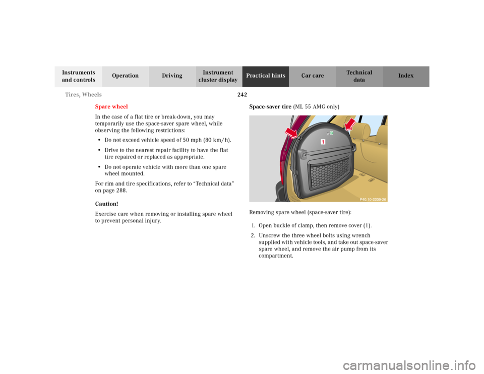
to prevent personal injury.Space-saver tire (ML 55 AMG only)
Removing spare wheel (space-saver tire):
1. Open buckle of clamp, then remove cover (1).
2. Unscrew the three wheel bolts using wrench
supplied with vehicle tools, and take out space-saver
spare wheel, and remove the air pump from its
compartment.
Page 246 of 317
243 Tires, Wheels
Te ch n ica l
data Instruments
and controlsOperation DrivingInstrument
cluster displayPractical hintsCar care Index Important!
To realize the total crumple zone in case of a rear end
collision, the space-saver spare wheel must be stored in
its holder with the tire deflated. Properly inflate the tire
prior to mounting it on the axle. See page 249 for
detailed instructions.
When storing the space-saver spare wheel in its holder,
tighten the three wheel bolts with a tightening torque of
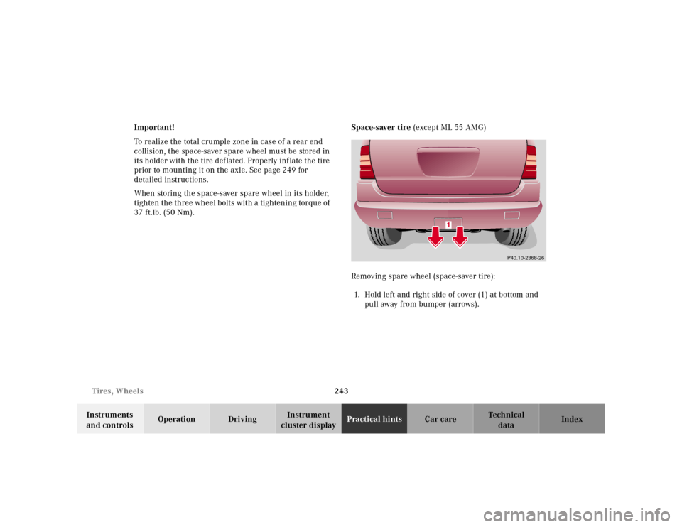
37 ft.lb. (50 Nm).Space-saver tire (except ML 55 AMG)
Removing spare wheel (space-saver tire):
1. Hold left and right side of cover (1) at bottom and
pu ll aw ay fr o m b u mpe r ( arr ows ) .
P40.10-2368-26
Page 247 of 317
244 Tires, Wheels
Te ch n ica l
data Instruments
and controlsOperation DrivingInstrument
cluster displayPractical hintsCar care Index
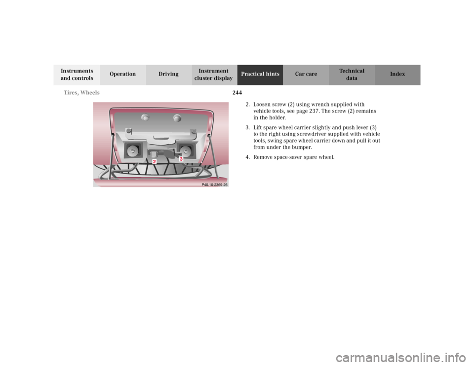
2. Loosen screw (2) using wrench supplied with
vehicle tools, see page 237. The screw (2) remains
in the holder.
3. Lift spare wheel carrier slightly and push lever (3)
to the right using screwdriver supplied with vehicle
tools, swing spare wheel carrier down and pull it out
from under the bumper.
4. Remove space-saver spare wheel.
Page 248 of 317
245 Tires, Wheels
Te ch n ica l
data Instruments
and controlsOperation DrivingInstrument
cluster displayPractical hintsCar care Index Changing wheels
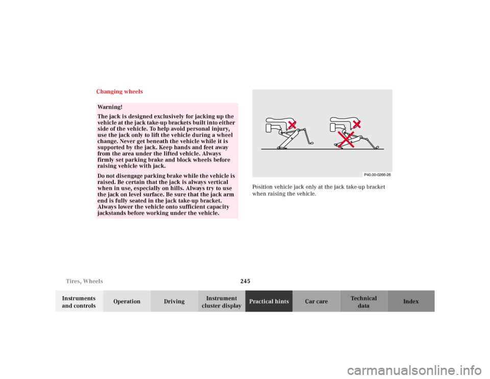
Position vehicle jack only at the jack take-up bracket
when raising the vehicle.
Wa r n i n g !
The jack is designed exclusively for jacking up the
veh icle at the jack take-u p brackets bu ilt i nto eit her
side of the vehicle. To help avoid personal injury,
use the jack only to lift the vehicle during a wheel
change. Never get beneath the vehicle while it is
supported by the jack. Keep hands and feet away
from the area under the lifted vehicle. Always
firmly set parking brake and block wheels before
raising vehicle with jack.Do not disengage parking brake while the vehicle is
raised. Be certain that the jack is always vertical
when in use, especially on hills. Always try to use
the jack on level surface. Be sure that the jack arm
end is fully seated in the jack take-up bracket.
Always lower the vehicle onto sufficient capacity
jackstands before working under the vehicle.
Page 249 of 317
246 Tires, Wheels
Te ch n ica l
data Instruments
and controlsOperation DrivingInstrument
cluster displayPractical hintsCar care Index
Move vehicle to a level area which is a safe distance
from the roadway.
Important!
The vehicle doors lock if the left front wheel rotates with
the engine running. Do not leave the engine running
while changing a wheel.
1. Set parking brake and turn on hazard warning
flasher.
2. Move selector lever to position “P” and turn off
engine, and remove key from the steering lock.
3. Prevent vehicle from rolling away by blocking
wheels with wheel chocks (not supplied with
vehicle) or sizable wood block or stone. When
changing a wheel on a hill, place chocks on the
downhill side blocking both wheels of the other
axle. On a level road, place one chock in front of and
one behind the wheel that is diagonally opposite to
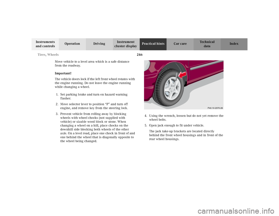
the wheel being changed.4. Using the wrench, loosen but do not yet remove the
wheel bolts.
5. Open jack enough to fit under vehicle.
The jack take-up brackets are located directly
behind the front wheel housings and in front of the
rear wheel housings.
P40.10-2370-26
Page 250 of 317
247 Tires, Wheels
Te ch n ica l
data Instruments
and controlsOperation DrivingInstrument
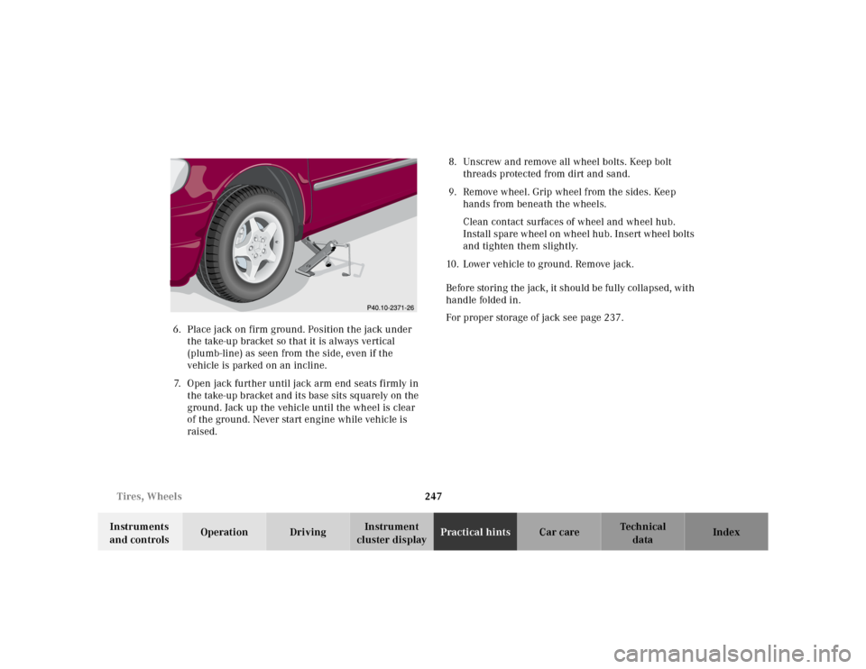
cluster displayPractical hintsCar care Index 6. Place jack on firm ground. Position the jack under
t he take-up bracket so t hat it is always ve rtical
(plumb-line) as seen from the side, even if the
vehicle is parked on an incline.
7. Open jack further until jack arm end seats firmly in
the take-up bracket and its base sits sq uarely on the
ground. Jack up the vehicle until the wheel is clear
of the ground. Never start engine while vehicle is
raised.8. Unscrew and remove all wheel bolts. Keep bolt
threads protected from dirt and sand.
9. Remove wheel. Grip wheel from the sides. Keep
hands from beneath the wheels.
Clean contact surfaces of wheel and wheel hub.
Install spare wheel on wheel hub. Insert wheel bolts
and tighten them slightly.
10. Lower vehicle to ground. Remove jack.
Before storing the jack, it should be fully collapsed, with
handle folded in.
For proper storage of jack see page 237.