torque MERCEDES-BENZ ML55AMG 2001 W163 Owner's Manual
[x] Cancel search | Manufacturer: MERCEDES-BENZ, Model Year: 2001, Model line: ML55AMG, Model: MERCEDES-BENZ ML55AMG 2001 W163Pages: 317, PDF Size: 10.4 MB
Page 173 of 317
170 Automatic transmission
Te ch n ica l
data Instruments
and controlsOperationDrivingInstrument
cluster displayPractical hints Car care Index
Press and hold selector lever in the ædirection:
The transmission will shift from the current gear
directly to gear range “D”.
Important!
With transmission in gear range “D”, “4” or “3”,
upshifting from 1st to 2nd to 3rd gear is delayed
depending on vehicle speed and engine temperature.
This allows the catalytic converter to heat up more
quickly to operating temperatures.During the brief warm-up period this delayed upshift
and increased engine noise might be perceived as a
malfunction. However, neither the engine nor
transmission are negatively affected by this mode of
operation.
The delayed upshift is effective with vehicle speeds
below 31 mph (50 km / h) at partial throttle and engine
temperatures below 95°F (35°C).
To avoid overrevving the engine when the selector lever
is moved to a lower gear range, the transmission will not
shift to a lower gear, if the engine’s revolutions per
minute limit would be exceeded. In this case there will
be no downshift, even when the vehicle speed reaches
the engine’s RPM limit of that gear, e.g. by applying the
service brakes. Continue driving in the usual manner.
The transmission will then shift down automatically.
To prevent the engine from laboring at low RPM when
driving uphill gradients or with your vehicle heavily
loaded, the automatic transmission will downshift when
necessary to maintain engine RPM within the best
torque range.
Wa r n i n g !
On slippery road surfaces, never downshift in order
to obtain braking action. This could result in drive
wheel slip and reduced vehicle control. Your
vehicle’s ABS will not prevent this type of loss of
control.
Page 188 of 317
185 Driving instructions
Te ch n ica l
data Instruments
and controlsOperationDrivingInstrument
cluster displayPractical hints Car care Index Driving on embankments, slopes and other steep
inclines should only be done straight up or downhill, i.e.
in the line of gravity.
Do not drive along the side of a slope (danger of vehicle
rollover). If in doing so, the vehicle begins to show a
tendency to roll, immediately steer into a line of gravity
(straight up or downhill).
To help avoid the vehicle rolling over, never turn it
around on steep inclines. If the vehicle cannot complete
the attempted climb, back it down in reverse gear.
Utilize the engine’s braking power when descending a
slope, observe the engine speed (do not overrev the
engine). Apply the service brake as needed.
Check the brakes after a lengthy downgrade drive.
Notes:
Avoid excessive engine speeds – drive with moderate
engine speeds (max. 3000 RPM).
Select gear range “2” or “1” on the automatic
transmission, see page 165.Traction in steep terrain:
Be easy on the accelerator and watch for continuous
wheel traction when driving in steep terrain.
The 4-ETS+ helps greatly when starting out on a steep
incline. The front wheels have then the tendency to slip
due to the weight reduction over the front axle. The ETS
recognizes the situation and limits the torque for the
front wheels by braking them. Simultaneously the
torque for the rear wheels is increased.
See page 203 for four wheel electronic traction system
(4-ETS+).
Driving across a hilltop:
To prevent the vehicle from speeding up too much after
climbing a hill, decelerate just ahead of a hilltop (do not
select gear range “N”). Use the momentum of the
vehicle to drive across the hilltop. Driving in this
manner prevents the vehicle from jumping across the
hilltop and thus loosing its forward momentum.
Page 208 of 317
205 Driving systems
Te ch n ica l
data Instruments
and controlsOperationDrivingInstrument
cluster displayPractical hints Car care Index Electronic stability program (ESP)
The ESP enhances directional control and reduces
driving wheel spin of the vehicle under various driving
conditions.
Over-/understeering of the vehicle is counteracted by
applying brakes to the appropriate wheel to create a
countervailing vehicle movement. Engine torque is also
limited. The ESP warning lamp, located in the
speedometer dial, starts to flash when ESP is in
operation.Important!
If the ESP warning lampv flashes:
•During take-off apply as little throttle as possible.
•While driving ease up on the accelerator.
•Adapt your speed and driving to the prevailing road
conditions.
•Do not switch off the ESP.
Caution!
If the vehicle is towed with the front axle raised (see
towing the vehicle on page 255), the engine must be
shut off (key in steering lock position 0 or 1). Otherwise,
the ESP will immediately be engaged and will apply the
rear wheel brakes.
Notes:
The malfunction indicator lamp for the ESP is combined
with that of the BAS.
The yellow BAS / ESP malfunction indicator lamp¿
in the instrument cluster and the yellow ESP warning
lampv in the speedometer dial come on with the
key in steering lock position 2. They should go out with
the engine running.
Wa r n i n g !
ESP cannot prevent the natural laws of physics
from acting on the vehicle, nor can it increase the
traction afforded. The ESP cannot prevent
accidents, including those resulting from excessive
speed in turns, or aquaplaning. Only a safe,
attentive, and skillful driver can prevent accidents.
The capabilities of an ESP equipped vehicle must
never be exploited in a reckless or dangerous
manner which could jeopardize the user’s safety or
the safety of others.
Page 210 of 317
207 Driving systems
Te ch n ica l
data Instruments
and controlsOperationDrivingInstrument
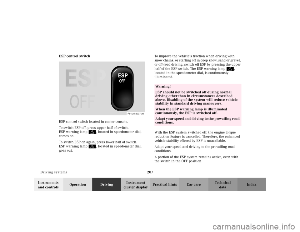
cluster displayPractical hints Car care Index ESP control switch
ESP control switch located in center console.
To switch ESP off, press upper half of switch.
ESP warning lamp v, located in speedometer dial,
comes on.
To switch ESP on again, press lower half of switch.
ESP warning lamp v, located in speedometer dial,
goes out.To improve the vehicle’s traction when driving with
snow chains, or starting off in deep snow, sand or gravel,
or off-road driving, switch off ESP by pressing the upper
half of the ESP switch. The ESP warning lampv,
located in the speedometer dial, is continuously
illuminated.
With the ESP system switched off, the engine torque
reduction feature is cancelled. Therefore, the enhanced
vehicle stability offered by ESP is unavailable.
Adapt your speed and driving to the prevailing road
conditions.
A portion of the ESP system remains active, even with
the switch in the OFF position.
P54.25-2037-26
Wa r n i n g !
ESP should not be switched off during normal
driving other than in circumstances described
above. Disabling of the system will reduce vehicle
stability in standard driving maneuvers.
When the ESP warning lamp is illuminated
continuously, the ESP is switched off.
Adapt your speed and driving to the prevailing road
conditions.
Page 246 of 317
243 Tires, Wheels
Te ch n ica l
data Instruments
and controlsOperation DrivingInstrument
cluster displayPractical hintsCar care Index Important!
To realize the total crumple zone in case of a rear end
collision, the space-saver spare wheel must be stored in
its holder with the tire deflated. Properly inflate the tire
prior to mounting it on the axle. See page 249 for
detailed instructions.
When storing the space-saver spare wheel in its holder,
tighten the three wheel bolts with a tightening torque of
37 ft.lb. (50 Nm).Space-saver tire (except ML 55 AMG)
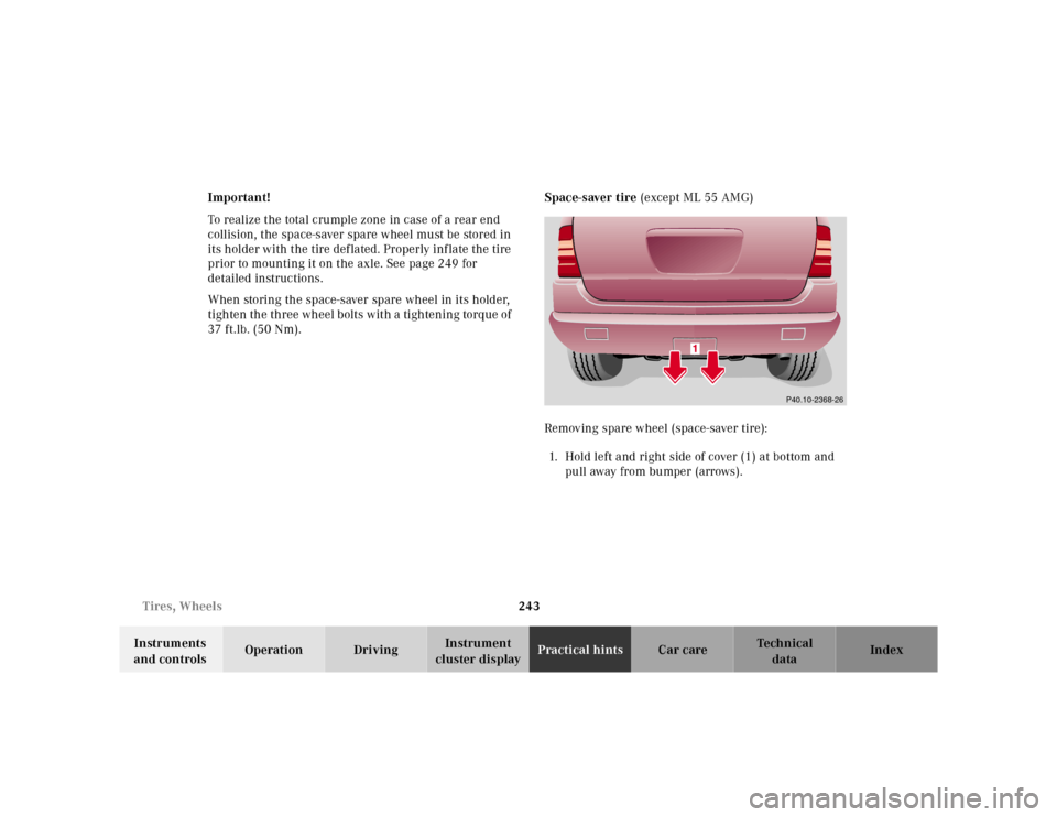
Removing spare wheel (space-saver tire):
1. Hold left and right side of cover (1) at bottom and
pu ll aw ay fr o m b u mpe r ( arr ows ) .
P40.10-2368-26
Page 251 of 317
248 Tires, Wheels
Te ch n ica l
data Instruments
and controlsOperation DrivingInstrument
cluster displayPractical hintsCar care Index
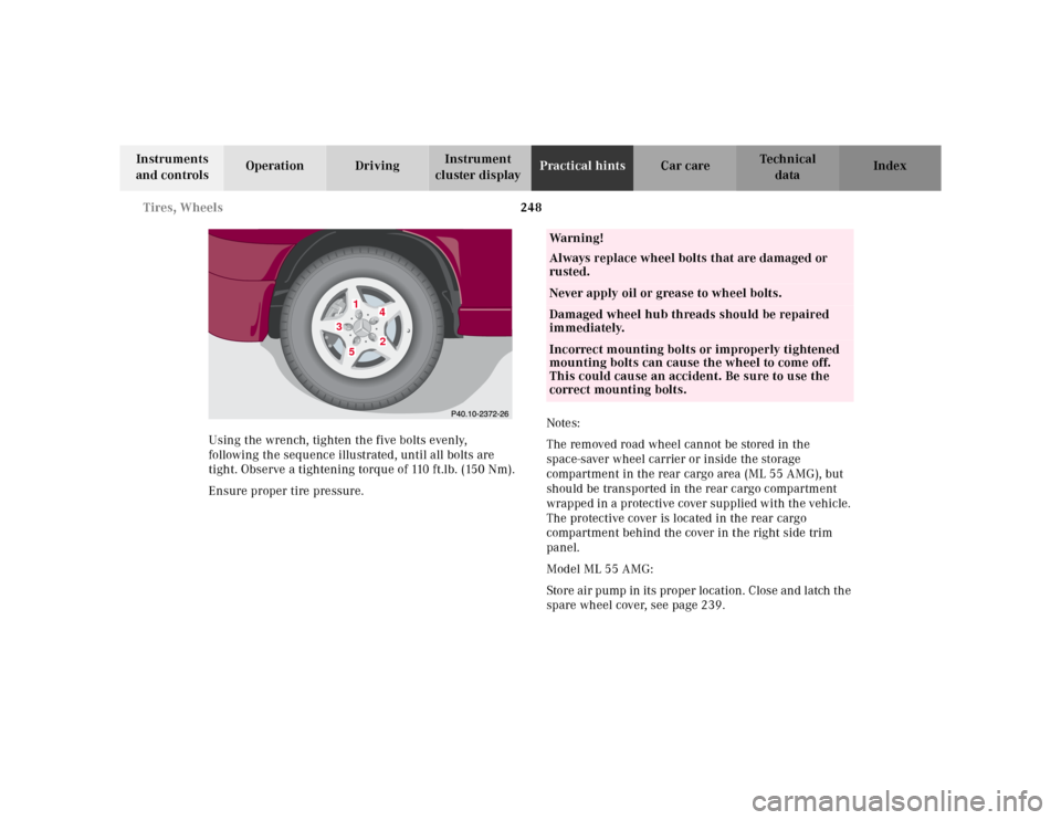
Using the wrench, tighten the five bolts evenly,
following the sequence illustrated, until all bolts are
tight. Observe a tightening torque of 110 ft.lb. (150 Nm).
Ensure proper tire pressure.Notes:
The removed road wheel cannot be stored in the
space-saver wheel carrier or inside the storage
compartment in the rear cargo area (ML 55 AMG), but
should be transported in the rear cargo compartment
wrapped in a protective cover supplied with the vehicle.
The protective cover is located in the rear cargo
compartment behind the cover in the right side trim
panel.
Model ML 55 AMG:
Store air pump in its proper location. Close and latch the
spare wheel cover, see page 239.
1
2
3
4
5
Wa r n i n g !
Always replace wheel bolts that are damaged or
rusted.Never apply oil or grease to wheel bolts.Damaged wheel hub threads should be repaired
immediately.Incorrect mounting bolts or improperly tightened
mounting bolts can cause the wheel to come off.
This could cause an accident. Be sure to use the
correct mounting bolts.
Page 290 of 317
287 Technical data
Te ch n ica l
data Instruments
and controlsOperation DrivingInstrument
cluster displayPractical hints Car care Index Technical data
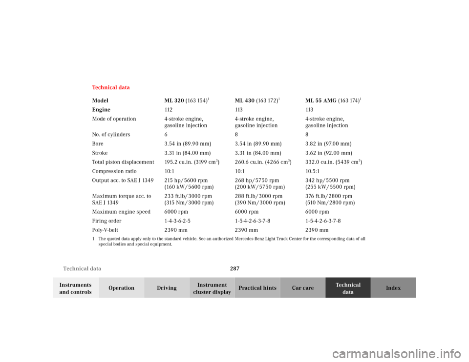
Model ML 320 (163 154)
1
ML 430 (163 172)
1
ML 55 AMG (163 174)
1
Engine112 113 113
Mode of operation 4-stroke engine,
gasoline injection4-stroke engine,
gasoline injection4-stroke engine,
gasoline injection
No. of cylinders688
Bore 3.54 in (89.90 mm) 3.54 in (89.90 mm) 3.82 in (97.00 mm)
Stroke 3.31 in (84.00 mm) 3.31 in (84.00 mm) 3.62 in (92.00 mm)
Total piston displacement 195.2 cu.in. (3199 cm
3) 260.6 cu.in. (4266 cm
3) 332.0 cu.in. (5439 cm
3)
Compression ratio 10:1 10:1 10.5:1
Output acc. to SAE J 1349 215 hp / 5600 rpm
(160 kW / 5600 rpm)268 hp / 5750 rpm
(200 kW / 5750 rpm)342 hp / 5500 rpm
(255 kW / 5500 rpm)
Maximum torque acc. to
SAE J 1349233 ft.lb / 3000 rpm
(315 Nm / 3000 rpm)288 ft.lb / 3000 rpm
(390 Nm / 3000 rpm)376 ft.lb / 2800 rpm
( 510 N m / 2 80 0 r p m )
Maximum engine speed 6000 rpm 6000 rpm 6000 rpm
Firing order 1-4-3-6-2-5 1-5-4-2-6-3-7-8 1-5-4-2-6-3-7-8
Poly-V-belt 2390 mm 2390 mm 2390 mm
1 The quoted data apply only to the standard vehicle. See an authorized Mercedes-Benz Light Truck Center for the corresponding data of all
special bodies and special equipment.
Page 293 of 317
290 Technical data
Te ch n ica l
data Instruments
and controlsOperation DrivingInstrument
cluster displayPractical hints Car care Index
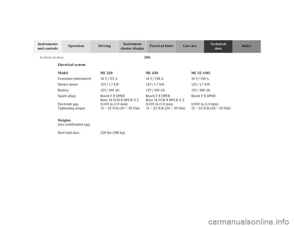
Electrical system
We i g h t s
(see certification tag) Model ML 320 ML 430 ML 55 AMG
Generator (alternator) 14 V / 115 A 14 V / 150 A 14 V / 150 A
S t a r te r m o to r 12 V / 1. 7 k W 12V / 1. 7 k W 12V / 1.7 k W
Battery 12V / 100 Ah 12V / 100 Ah 12V / 100 Ah
Spark plugs
Electrode gap
Tightening torqueBosch F 8 DPER
Beru 14 FGH 8 DPUR X 2
0.039 in (1.0 mm)
15–22ft.lb (20–30Nm)Bosch F 8 DPER
Beru 14 FGH 8 DPUR X 2
0.039 in (1.0 mm)
15–22ft.lb (20–30Nm)Bosch F 8 DPER
0.039 in (1.0 mm)
15–22ft.lb (20–30Nm)
Roof load max. 220 lbs (100 kg)