trunk MERCEDES-BENZ R-CLASS FAMILY TOURER 2012 Owners Manual
[x] Cancel search | Manufacturer: MERCEDES-BENZ, Model Year: 2012, Model line: R-CLASS FAMILY TOURER, Model: MERCEDES-BENZ R-CLASS FAMILY TOURER 2012Pages: 368, PDF Size: 29.05 MB
Page 20 of 368
Maximum load on a tire
(definition) ..................................... 345
Maximum permissible tire
pressure (definition) ....................... 344
Maximum tire load .........................337
Maximum tire load (definition) .......344
Optional equipment weight
(definition) ..................................... 345
PSI (pounds per square inch)
(definition) ..................................... 345
Replacing ....................................... 346
Service life ..................................... 323
Sidewall (definition) .......................345
Speed index (definition) .................344
Storing ........................................... 347
Structure and characteristics
(definition) ..................................... 343
Temperature .................................. 339
TIN (Tire Identification Number)
(definition) ..................................... 345
Tire bead (definition) ......................345
Tire pressure (definition) ................345
Tire pressures (recommended) ......343
Tire size (data) ............................... 347
Tire size designation, load-bearing
capacity, speed index ....................340
Tire tread ....................................... 323
Tire tread (definition) .....................345
Total load limit (definition) .............346
Traction ......................................... 338
Traction (definition) .......................345
Tread wear ..................................... 338
TWR (permissible trailer drawbar
noseweight) (definition) .................345
Uniform Tire Quality Grading
Standards ...................................... 338
Uniform Tire Quality Grading
Standards (definition) ....................343
Unladen weight (definition) ............344
Wear indicator (definition) .............346
Wheel rim (definition) ....................344
see Flat tire
Top Tether ............................................ 60
Towing Important safety guidelines ...........315
Installing the towing eye ................315
Removing the towing eye ...............316Towing a trailer
Coupling up a trailer ......................192
Decoupling a trailer .......................193
Driving tips .................................... 191
Important safety notes ..................191
Lights display message ..................222
Power supply ................................. 194
Shift range ..................................... 153
Towing away
With both axles on the ground .......316
Tow-starting
Emergency engine starting ............317
Important safety notes ..................315
Trailer
Towing ........................................... 192
Trailer loads and drawbar
noseweights ...................................... 194
Trailer towing Blind Spot Assist ............................ 191
ESP ®
................................................ 67
PARKTRONIC ................................. 186
Permissible trailer loads and
drawbar noseweights .....................194
Towing a trailer .............................. 192
Transmission
see Automatic transmission
Transporting the vehicle .................. 316
Trim pieces (cleaning instructions) . 293
Trip computer (on-board
computer) .......................................... 210
Trip meter see Trip odometer
Trip odometer
Calling up ....................................... 202
Resetting (on-board computer) ......211
Trunk
see Tailgate
Turn signals
Changing bulbs (front) ...................122
Display message ............................ 222
Switching on/off ........................... 117
see Turn signals
TWR (Tongue Weight Rating)
(definition) ......................................... 345
Type identification plate see Vehicle identification plate 18Index
Page 60 of 368
GWARNING
When leaving the vehicle, always remove the
SmartKey from the ignition lock. Always take
the SmartKey with you and lock the vehicle.
Do not leave children unattended in the
vehicle, even if they are secured in a child
restraint system, or with access to an
unlocked vehicle. A child's unsupervised
access to a vehicle could result in an accident
and/or serious personal injury. The children
could:
R injure themselves on parts of the vehicle
R be seriously or fatally injured through
excessive exposure to extreme heat or cold
R injure themselves or cause an accident with
vehicle equipment that can be operated
even if the SmartKey is removed from the
ignition lock or removed from the vehicle,
such as seat adjustment, steering wheel
adjustment, or the memory function
If children open a door, they could injure other
persons or get out of the vehicle and injure
themselves or be injured by following traffic.
Do not expose the child restraint system to
direct sunlight. The child restraint system's
metal parts, for example, could become very
hot, and the child could be burned on these
parts.
GWARNING
Do not carry heavy or hard objects in the
passenger compartment or trunk unless they
are firmly secured in place.
Unsecured or improperly positioned cargo
increases a child's risk of injury in the event
of
R strong braking maneuvers
R sudden changes of direction
R an accident
Special seat belt retractor
All seat belts except the driver's seat belt are
equipped with a special seat belt retractor.
When activated, the special seat belt
retractor ensures the seat belt will not
slacken once the child restraint system has
been secured.
Installing a child restraint system:XAlways comply with the manufacturer's
installation instructions.XPull the seat belt smoothly from the inertia
reel.XEngage the seat belt tongue in the belt
buckle.
Activating the special seat belt retractor:
XPull the seat belt out fully and let the inertia
reel retract it again.
While the seat belt is retracting, you should
hear a ratcheting sound. The special seat
belt retractor is enabled.XPush down on the child restraint system to
take up any slack.
Removing a child restraint system/
deactivating the special seat belt retractor:
XAlways comply with the manufacturer's
installation instructions.XPress the seat belt release button and
guide the belt tongue to the belt outlet.
The special seat belt retractor is
deactivated.GWARNING
Never release the seat belt buckle while the
vehicle is in motion, since the special seat belt
retractor will be deactivated.
LATCH-type (ISOFIX) child seat anchors
in the rear
GWARNING
Children that are too large for a child restraint
must travel in seats using normal seat belts.
Position shoulder belt across the chest and
shoulder, not face or neck.
In order to attain the correct seating position
for children weighing over 41 lb (18 kg), it may
be necessary to use a booster seat until they
reach a height where a normal lap/shoulder
58Children in the vehicleSafety
Page 164 of 368
use a sponge and cold water to clean it. DEF
residues crystallize after time and
contaminate the affected surfaces.
! DEF is not a fuel additive and must not be
added to the fuel tank. If DEF is added to
the fuel tank, this can lead to engine
damage.
i If you are adding between maintenance
intervals, add approximately 1 gallon (3.8 l)
of DEF to the DEF tank. One gallon (3.8 l)
of DEF is approximately 2 DEF refill bottles.
For further information on DEF, see:
( Y page 357).
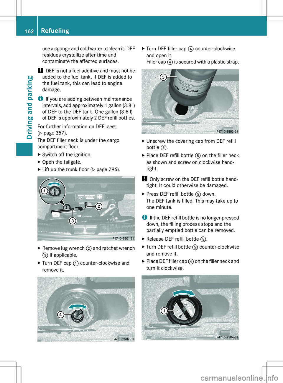
The DEF filler neck is under the cargo
compartment floor.XSwitch off the ignition.XOpen the tailgate.XLift up the trunk floor ( Y page 296).XRemove lug wrench ; and ratchet wrench
= if applicable.XTurn DEF cap : counter-clockwise and
remove it.XTurn DEF filler cap ? counter-clockwise
and open it.
Filler cap ? is secured with a plastic strap.XUnscrew the covering cap from DEF refill
bottle A.XPlace DEF refill bottle A on the filler neck
as shown and screw on clockwise hand-
tight.
! Only screw on the DEF refill bottle hand-
tight. It could otherwise be damaged.
XPress DEF refill bottle A down.
The DEF tank is filled. This may take up to
one minute.
i If the DEF refill bottle is no longer pressed
down, the filling process stops and the
partially emptied bottle can be removed.
XRelease DEF refill bottle A.XTurn DEF refill bottle A counter-clockwise
and remove it.XPlace DEF filler cap ? on the filler neck and
turn it clockwise.162RefuelingDriving and parking
Page 256 of 368
third-row seat occupants to use folded
second-row seats as a footrest while driving.
Third-row seat occupants must, like all vehicle
occupants, keep both feet on the floor in front
of their seat. Otherwise, occupants could
slide under their seat belt in a collision. If
occupants slide under the seat belt, it would
apply force at the abdomen or neck. That
could cause serious or even fatal injuries. Do
not fold the second-row seats and allow third-
row seat occupants to use folded second-row
seats as a table while driving. Objects placed
on folded second-row seats may come loose
during braking, vehicle maneuvers, or an
accident and be thrown around the vehicle
interior. Objects thrown around the vehicle
interior may cause an accident and/or
serious personal injury.
! Make absolutely sure that you adhere to
the specified folding order when fully
enlarging the cargo compartment:
R fold down the center seat in the 2nd row
of seats (7-seat vehicles)
R fold down the outer seats in the 2nd row
of seats
R fold down the seats in the 3rd row of
seats
You could otherwise damage the seats.
Folding down the center seat in the 2nd
row of seats
! Close the cup holder in the 2nd row of
seats before folding down the 2nd row of
seats. You could otherwise damage the
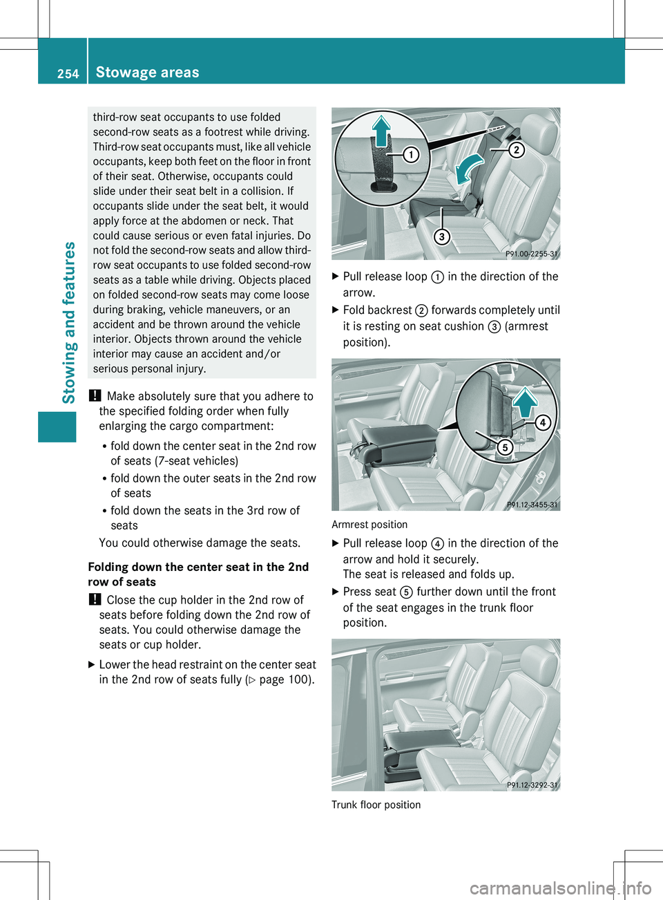
seats or cup holder.XLower the head restraint on the center seat
in the 2nd row of seats fully ( Y page 100).XPull release loop : in the direction of the
arrow.XFold backrest ; forwards completely until
it is resting on seat cushion = (armrest
position).
Armrest position
XPull release loop ? in the direction of the
arrow and hold it securely.
The seat is released and folds up.XPress seat A further down until the front
of the seat engages in the trunk floor
position.
Trunk floor position
254Stowage areasStowing and features
Page 298 of 368
Useful information
i This Operator's Manual describes all
models and all standard and optional
equipment of your vehicle available at the
time of publication of the Operator's
Manual. Country-specific differences are
possible. Please note that your vehicle may
not be equipped with all features
described. This also applies to safety-
related systems and functions.
i Please read the information on qualified
specialist workshops ( Y page 24).
Where will I find...?
First-aid kit
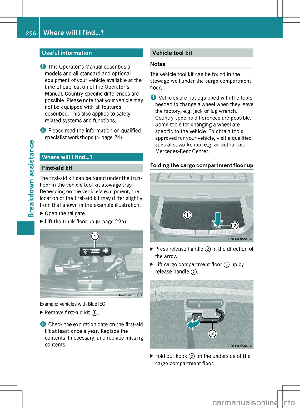
The first-aid kit can be found under the trunk
floor in the vehicle tool kit stowage tray.
Depending on the vehicle's equipment, the
location of the first-aid kit may differ slightly
from that shown in the example illustration.
XOpen the tailgate.XLift the trunk floor up ( Y page 296).
Example: vehicles with BlueTEC
XRemove first-aid kit :.
i
Check the expiration date on the first-aid
kit at least once a year. Replace the
contents if necessary, and replace missing
contents.
Vehicle tool kit
Notes
The vehicle tool kit can be found in the
stowage well under the cargo compartment
floor.
i Vehicles are not equipped with the tools
needed to change a wheel when they leave
the factory, e.g. jack or lug wrench.
Country-specific differences are possible.
Some tools for changing a wheel are
specific to the vehicle. To obtain tools
approved for your vehicle, visit a qualified
specialist workshop, e.g. an authorized
Mercedes-Benz Center.
Folding the cargo compartment floor up
XPress release handle ; in the direction of
the arrow.XLift cargo compartment floor : up by
release handle ;.XFold out hook = on the underside of the
cargo compartment floor.296Where will I find...?Breakdown assistance
Page 299 of 368
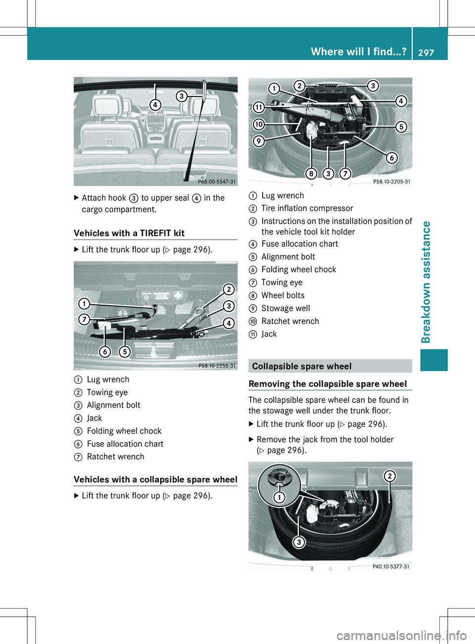
XAttach hook = to upper seal ? in the
cargo compartment.
Vehicles with a TIREFIT kit
XLift the trunk floor up ( Y page 296).:Lug wrench;Towing eye=Alignment bolt?JackAFolding wheel chockBFuse allocation chartCRatchet wrench
Vehicles with a collapsible spare wheel
XLift the trunk floor up ( Y page 296).:Lug wrench;Tire inflation compressor=Instructions on the installation position of
the vehicle tool kit holder?Fuse allocation chartAAlignment boltBFolding wheel chockCTowing eyeDWheel boltsEStowage wellFRatchet wrenchGJack
Collapsible spare wheel
Removing the collapsible spare wheel
The collapsible spare wheel can be found in
the stowage well under the trunk floor.
XLift the trunk floor up ( Y page 296).XRemove the jack from the tool holder
( Y page 296).Where will I find...?297Breakdown assistance
Page 302 of 368
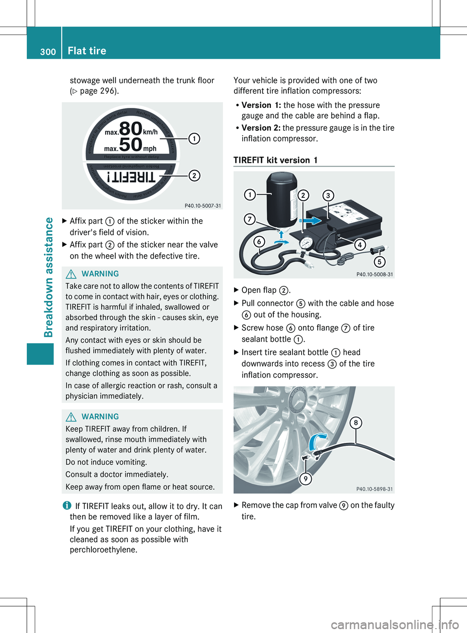
stowage well underneath the trunk floor
( Y page 296).XAffix part : of the sticker within the
driver's field of vision.XAffix part ; of the sticker near the valve
on the wheel with the defective tire.GWARNING
Take care not to allow the contents of TIREFIT
to come in contact with hair, eyes or clothing.
TIREFIT is harmful if inhaled, swallowed or
absorbed through the skin - causes skin, eye
and respiratory irritation.
Any contact with eyes or skin should be
flushed immediately with plenty of water.
If clothing comes in contact with TIREFIT,
change clothing as soon as possible.
In case of allergic reaction or rash, consult a
physician immediately.
GWARNING
Keep TIREFIT away from children. If
swallowed, rinse mouth immediately with
plenty of water and drink plenty of water.
Do not induce vomiting.
Consult a doctor immediately.
Keep away from open flame or heat source.
i If TIREFIT leaks out, allow it to dry. It can
then be removed like a layer of film.
If you get TIREFIT on your clothing, have it
cleaned as soon as possible with
perchloroethylene.
Your vehicle is provided with one of two
different tire inflation compressors:
R Version 1: the hose with the pressure
gauge and the cable are behind a flap.
R Version 2: the pressure gauge is in the tire
inflation compressor.
TIREFIT kit version 1XOpen flap ;.XPull connector A with the cable and hose
B out of the housing.XScrew hose B onto flange C of tire
sealant bottle :.XInsert tire sealant bottle : head
downwards into recess = of the tire
inflation compressor.XRemove the cap from valve E on the faulty
tire.300Flat tireBreakdown assistance
Page 306 of 368
handling characteristics of the vehicle may
change.
Adapt your style of driving accordingly.
Never operate the vehicle with more than one
emergency spare wheel/spare wheel that
differs in size.
Only use an emergency spare wheel/spare
wheel of a differing size briefly and do not
switch off ESP ®
.
When using an emergency spare wheel, you
must not exceed the maximum speed of
50 mph (80 km/h).GWARNING
Have the emergency spare wheel/spare
wheel replaced with a new wheel as soon as
possible at a qualified specialist workshop
which has the necessary specialist knowledge
and tools to carry out the work required.
Mercedes-Benz recommends that you use an
authorized Mercedes-Benz Center for this
purpose. In particular, work relevant to safety
or on safety-related systems must be carried
out at a qualified specialist workshop.
i Vehicles without a spare wheel/
emergency spare wheel are not equipped
with a tire-change tool kit at the factory. For
more information on which tools are
required to perform a wheel change on your
vehicle, e.g. wheel chock, lug wrench or
alignment bolt, consult an authorized
Mercedes-Benz Center.
XPrepare the vehicle as described
( Y page 299).XIf a trailer is coupled to the vehicle,
uncouple it.XRemove the following items (depending on
the vehicle's equipment) from the stowage
well under the trunk floor:
R the emergency spare wheel 35
R the wheel bolts for the emergency spare
wheel 35
R the jackRthe ratchet wrench
R the lug wrench
R the folding wheel chock
R the alignment bolt
R the tire inflation compressor 35XSecure the vehicle to prevent it from rolling
away.
Securing the vehicle to prevent it from
rolling away
GWARNING
Only jack up the vehicle on level ground or on
slight inclines/declines. The vehicle could
otherwise fall off the jack and injure you or
others.
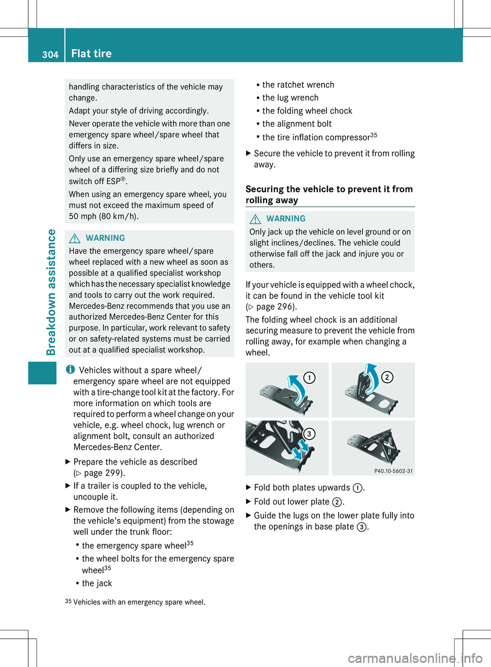
If your vehicle is equipped with a wheel chock,
it can be found in the vehicle tool kit
( Y page 296).
The folding wheel chock is an additional
securing measure to prevent the vehicle from
rolling away, for example when changing a
wheel.
XFold both plates upwards :.XFold out lower plate ;.XGuide the lugs on the lower plate fully into
the openings in base plate =.35
Vehicles with an emergency spare wheel.304Flat tireBreakdown assistance
Page 320 of 368
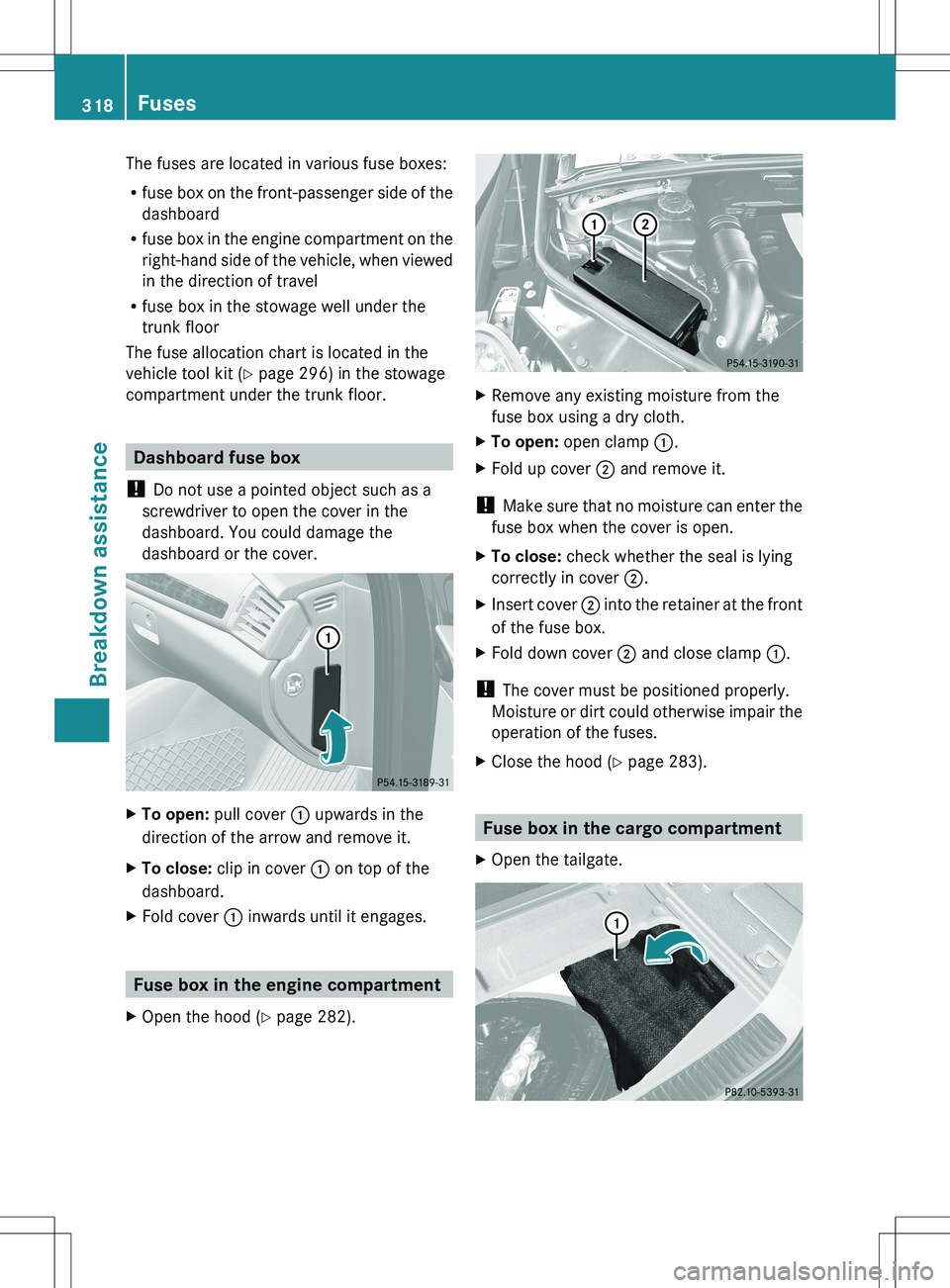
The fuses are located in various fuse boxes:
R fuse box on the front-passenger side of the
dashboard
R fuse box in the engine compartment on the
right-hand side of the vehicle, when viewed
in the direction of travel
R fuse box in the stowage well under the
trunk floor
The fuse allocation chart is located in the
vehicle tool kit ( Y page 296) in the stowage
compartment under the trunk floor.
Dashboard fuse box
! Do not use a pointed object such as a
screwdriver to open the cover in the
dashboard. You could damage the
dashboard or the cover.
XTo open: pull cover : upwards in the
direction of the arrow and remove it.XTo close: clip in cover : on top of the
dashboard.XFold cover : inwards until it engages.
Fuse box in the engine compartment
XOpen the hood ( Y page 282).XRemove any existing moisture from the
fuse box using a dry cloth.XTo open: open clamp :.XFold up cover ; and remove it.
!
Make sure that no moisture can enter the
fuse box when the cover is open.
XTo close: check whether the seal is lying
correctly in cover ;.XInsert cover ; into the retainer at the front
of the fuse box.XFold down cover ; and close clamp :.
!
The cover must be positioned properly.
Moisture or dirt could otherwise impair the
operation of the fuses.
XClose the hood ( Y page 283).
Fuse box in the cargo compartment
XOpen the tailgate.318FusesBreakdown assistance
Page 321 of 368
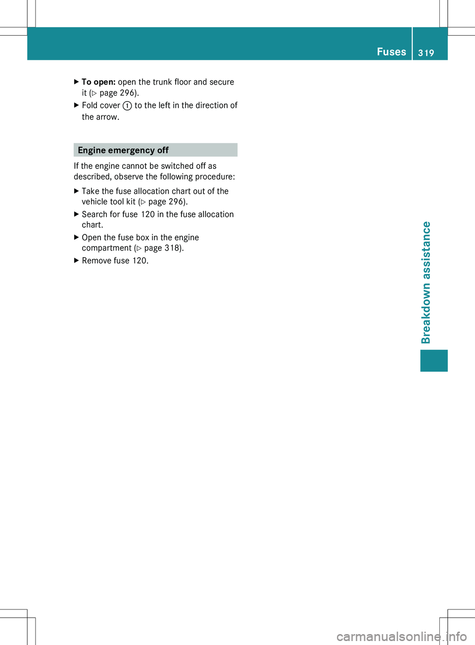
XTo open: open the trunk floor and secure
it ( Y page 296).XFold cover : to the left in the direction of
the arrow.
Engine emergency off
If the engine cannot be switched off as
described, observe the following procedure:
XTake the fuse allocation chart out of the
vehicle tool kit ( Y page 296).XSearch for fuse 120 in the fuse allocation
chart.XOpen the fuse box in the engine
compartment ( Y page 318).XRemove fuse 120.Fuses319Breakdown assistanceZ