tailgate MERCEDES-BENZ R-CLASS MPV 2008 Owner's Manual
[x] Cancel search | Manufacturer: MERCEDES-BENZ, Model Year: 2008, Model line: R-CLASS MPV, Model: MERCEDES-BENZ R-CLASS MPV 2008Pages: 373, PDF Size: 6.75 MB
Page 254 of 373

Where will I find...?
251
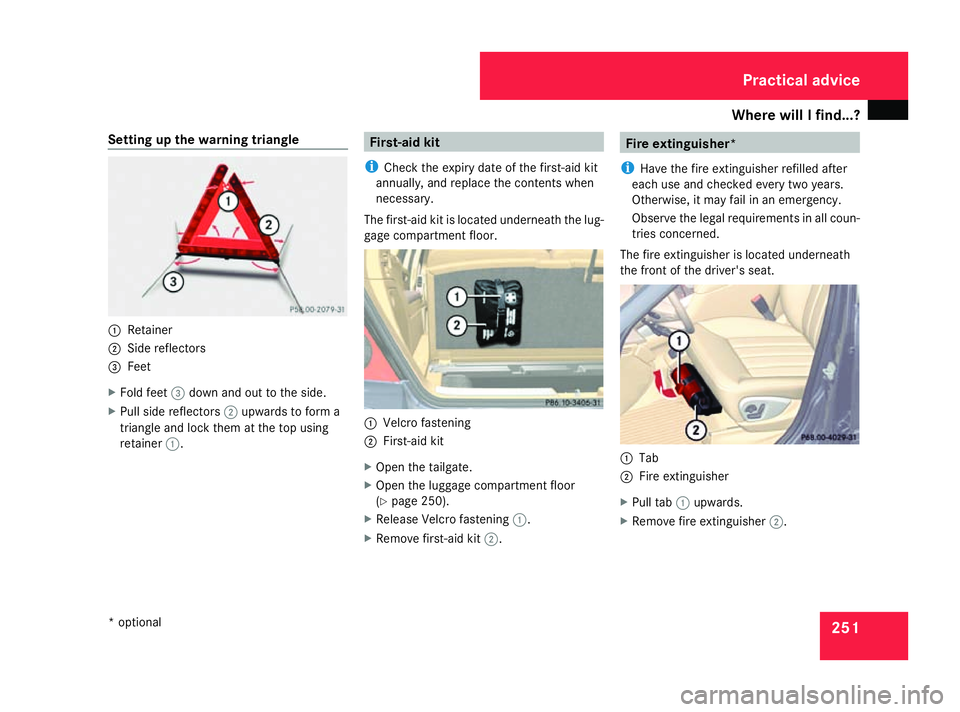
Setting up the warning triangle
1
Retainer
2 Side reflectors
3 Feet
X Fold feet 3down and out to the side.
X Pull side reflectors 2upwards to form a
triangle and lock them at the top using
retainer 1. First-aid kit
i Check the expiry date of the first-aid kit
annually, and replace the contents when
necessary.
The first-aid kit is located underneath the lug-
gage compartment floor. 1
Velcro fastening
2 First-aid kit
X Open the tailgate.
X Open the luggage compartment floor
(Y page 250).
X Release Velcro fastening 1.
X Remove first-aid kit 2. Fire extinguisher*
i Have the fire extinguisher refilled after
each use and checked every two years.
Otherwise, it may fail in an emergency.
Observe the legal requirements in all coun-
tries concerned.
The fire extinguisher is located underneath
the front of the driver's seat. 1
Tab
2 Fire extinguisher
X Pull tab 1upwards.
X Remove fire extinguisher 2. Practical advice
* optional
251_AKB; 5; 7, en-GB
wobuchh,
Version: 2.10.6 2008-05-11T14:51:51+02:00 - Seite 251 ZDateiname: 6515_1825_02_buchblock.pdf; preflight
Page 255 of 373

Where will I find...?
252 Vehicle tool kit, jack, TIREFIT kit and
emergency spare wheel*
The vehicle tool kit, jack, TIREFIT kit and
emergency spare wheel* are in the stowage
compartment under the luggage compart-
ment floor. G
Risk of injury
The jack is designed only to raise and hold
the vehicle for a short time while a wheel
is being changed.
You must use stands if you are carrying out
work on the vehicle.
Make sure that the jack is placed on a firm,
non-slip and level surface. Do not use
wooden blocks or similar objects as a jack
underlay. Otherwise, the jack will not be
able to achieve its load-bearing capacity
due to the restricted height.
Do not start the engine at any time while a
wheel is being changed.
Do not lie under the vehicle when it is being
supported by the jack. If you do not raise
the vehicle as described, it could slip off the
jack (e.g. if the engine is started or a door
or the tailgate is opened or closed) and you
could be seriously injured. X
Open the tailgate.
X Open the luggage compartment floor
(Y page 250).
! If the luggage compartment cover* is fit-
ted, roll it open fully.
Only for luggage compartment covers* fit-
ted behind the 3rd row of seats:
Fold forwards the section of the luggage
compartment cover* that is still protrud-
ing. Otherwise the strap of the retaining
hook may damage the luggage compart-
ment cover*.
Vehicles with a TIREFIT kit i
Depending on the date of production of
the vehicle, the appearance and stowage
location of the jack and of the other tools
may differ from those illustrated. Example
1
Ball coupling of the trailer tow hitch*
2 Folding wheel chock
3 Jack, ratchet ring spanner
4 TIREFIT kit 30
5 Electric air pump 30
6 Fuse allocation chart
7 Wheel wrench
8 Towing eye
9 Centring pin
Vehicles with an emergency spare
wheel* i
Depending on the date of production of
the vehicle, the appearance and stowage
30 Not on vehicles with MOExtended run-flat system. Practical advice
* optional
251_AKB; 5; 7, en-GB
wobuchh,
Version: 2.10.6 2008-05-11T14:51:51+02:00 - Seite 252Dateiname: 6515_1825_02_buchblock.pdf; preflight
Page 257 of 373

Where will I find...?
2541
Guides
2 Emergency spare wheel*
X Lay emergency spare wheel* 2in the
emergency spare wheel well.
i Make sure that emergency spare wheel*
2 is positioned on guides 1precisely.
X Lay the emergency spare wheel in the
emergency spare wheel well (Y page 250).
X Lay the tool holder in emergency spare
wheel* 2so that the electric air pump is
pointing towards the tailgate
(Y page 252). X
Turn the tool holder approximately 180°,
so that the electrical air pump points for-
wards.
The tool holder should now be positioned
in accordance with the instructions on the
installation position.
X Turn the tool holder screw clockwise into
the tool holder as far as it will go.
Setting up the foldable wheel chock The folding wheel chock serves as an addi-
tional measure for securing the vehicle
against rolling away, e.g. when a wheel is
being changed.
1
To fold the plates upwards
2 To fold out the lower plate
3 To insert the plate X
Fold both plates 1upwards.
X Fold out lower plate 2.
X Guide the lugs on the lower plate fully into
the openings in base plate 3.Practical advice
* optional
251_AKB; 5; 7, en-GB
wobuchh , Version: 2.10.6
2008-05-11T14:51:51+02:00 - Seite 254 Dateiname: 6515_1825_02_buchblock.pdf; preflight
Page 267 of 373

Display
messages 264 Display messages Possible cause/consequence Possible solution
DISTRONIC and
SPEEDTRONIC inoperative
Distronic
* andSpeedtronic are unavaila-
ble. X
Visit a qualified specialist workshop. Cruise control - - - km/h A condition for activating cruise control
has not been met. X
Activate ESP ®
(Ypage 61)
X If conditions permit, drive faster than
30 km/h and store the speed (Y page 140).Symbol messages
G
Risk of accident and injury
The operating safety of your vehicle could be compromised if service work is carried out improperly. You could lose control of the vehicle,
thereby causing an accident. Safety systems may also not be able to protect you or others as intended.
Always have maintenance work carried out at a qualified specialist workshop which has the necessary specialist knowledge and tools to
carry out the work required.
Mercedes-Benz recommends that you use a Mercedes-Benz Service Centre for this purpose.
In particular, work relevant to safety or on safety-related systems must be carried out at a qualified specialist workshop. Display messages Possible cause/consequence Possible solution
a This message always appears when the
tailgate is open. X
Close the tailgate. G
Risk of accident
Vehicles with an anti-theft alarm sys-
tem*:
You are driving with the bonnet open. X
Stop the vehicle. Pay attention to the traffic
conditions as you do so.
X Close the bonnet. Practical advice
* optional
251_AKB; 5; 7, en-GB
wobuchh,
Version: 2.10.6 2008-05-11T14:51:51+02:00 - Seite 264Dateiname: 6515_1825_02_buchblock.pdf; preflight
Page 291 of 373

Troubleshooting
288 Fuel and fuel tank
Problem Possible cause/consequence Suggested solutions
Fuel is leaking from the vehicle.
G
Risk of explosion or fire
The fuel line or the fuel tank is
defective. X
Turn the key to position 0(Y page 76) in the ignition lock immedi-
ately and remove it.
X Do not restart the engine under any circumstances.
X Consult a qualified specialist workshop. The fuel filler flap cannot be
opened. The fuel filler flap is not released.
The batteries in the vehicle key or
the KEYLESS GO key
* are dis-
charged. X
Unlock the vehicle using the emergency key element
(Y page 302).
X Open the tailgate (Y page 71).
X Manually unlock the fuel filler flap via the emergency release
(Y page 303). The fuel filler flap is released, but
the opening mechanism is jam-
med. X
Consult a qualified specialist workshop. Practical advice
* optional
251_AKB; 5; 7, en-GB
wobuchh,
Version: 2.10.6 2008-05-11T14:51:51+02:00 - Seite 288Dateiname: 6515_1825_02_buchblock.pdf; preflight
Page 306 of 373

Locking/unlocking in an emergency
303
X
Turn the emergency key element back and
remove it.
X Pull the door handle again. Locking the vehicle
If the vehicle can no longer be locked cen-
trally with the key or the KEYLESS GO key*:
X Close the front-passenger door, the rear
door on the front-passenger side and the
tailgate.
X Open the driver's door and the rear door on
the driver's side.
X Press the locking button on the driver's
door (Y page 75).
The locking knobs in the front-passenger
door and in the rear doors drop down.
X Press the locking knobs in the front-
passenger and rear doors down manually if
necessary.
X Exit the vehicle.
X Close the driver's door.
X Enter the vehicle through the rear door on
the driver's side.
X Push the locking pin in the driver's door
down from the inside.
X Exit the vehicle. i
Ensure that you have the vehicle key on
your person and that it is not left in the
vehicle, as the vehicle will be locked after
the next step.
X Close the rear door on the driver's side.
The vehicle is locked. Emergency fuel filler flap release
G
Risk of injury
The edges on the inside of the vehicle body
can be sharp. You could injure yourself
when using the fuel filler flap emergency
release. Avoid contact with the edges on
the inside of the vehicle body.
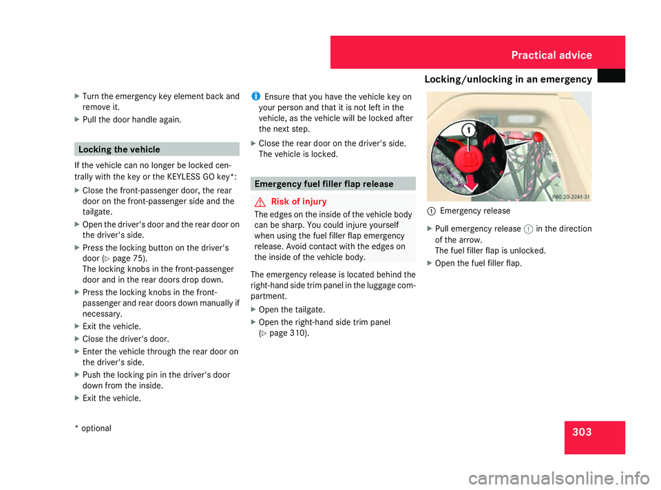
The emergency release is located behind the
right-hand side trim panel in the luggage com-
partment.
X Open the tailgate.
X Open the right-hand side trim panel
(Y page 310). 1
Emergency release
X Pull emergency release 1in the direction
of the arrow.
The fuel filler flap is unlocked.
X Open the fuel filler flap. Practical advice
* optional
251_AKB; 5; 7, en-GB
wobuchh,
Version: 2.10.6 2008-05-11T14:51:51+02:00 - Seite 303 ZDateiname: 6515_1825_02_buchblock.pdf; preflight
Page 314 of 373

Replacing the wiper blades
311
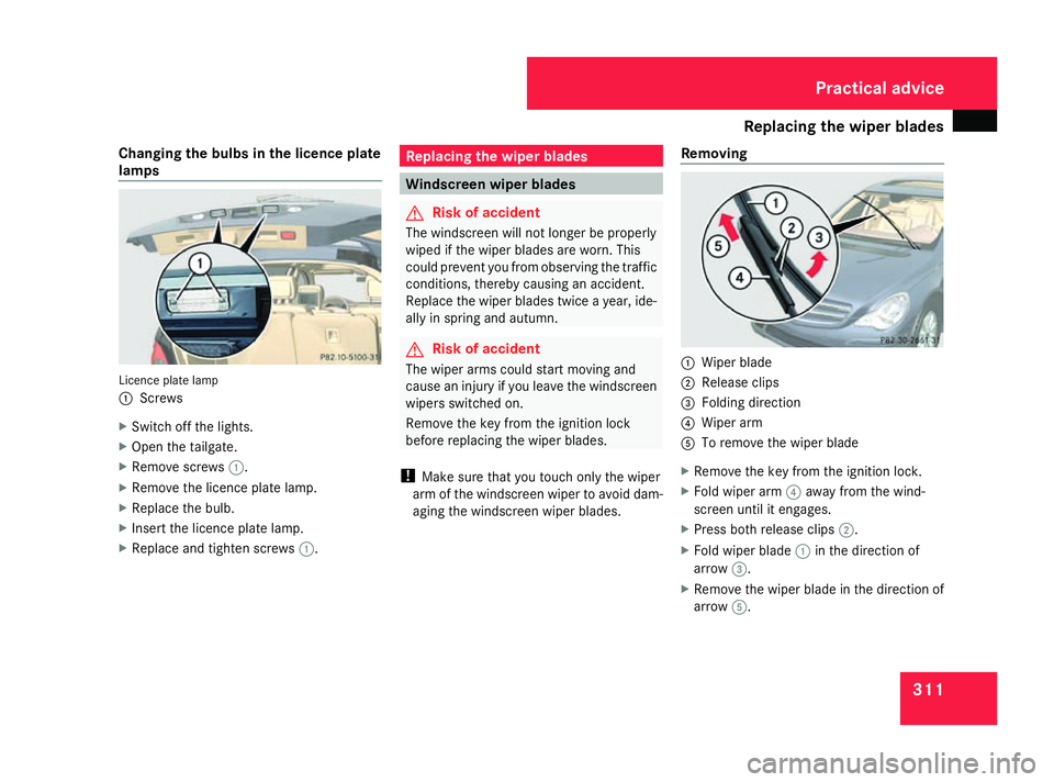
Changing the bulbs in the licence plate
lamps
Licence plate lamp
1
Screws
X Switch off the lights.
X Open the tailgate.
X Remove screws 1.
X Remove the licence plate lamp.
X Replace the bulb.
X Insert the licence plate lamp.
X Replace and tighten screws 1. Replacing the wiper blades
Windscreen wiper blades
G
Risk of accident
The windscreen will not longer be properly
wiped if the wiper blades are worn. This
could prevent you from observing the traffic
conditions, thereby causing an accident.
Replace the wiper blades twice a year, ide-
ally in spring and autumn. G
Risk of accident
The wiper arms could start moving and
cause an injury if you leave the windscreen
wipers switched on.
Remove the key from the ignition lock
before replacing the wiper blades.
! Make sure that you touch only the wiper
arm of the windscreen wiper to avoid dam-
aging the windscreen wiper blades. Removing 1
Wiper blade
2 Release clips
3 Folding direction
4 Wiper arm
5 To remove the wiper blade
X Remove the key from the ignition lock.
X Fold wiper arm 4away from the wind-
screen until it engages.
X Press both release clips 2.
X Fold wiper blade 1in the direction of
arrow 3.
X Remove the wiper blade in the direction of
arrow 5. Practical advice
251_AKB; 5; 7, en-GB
wobuchh,
Version: 2.10.6 2008-05-11T14:51:51+02:00 - Seite 311 ZDateiname: 6515_1825_02_buchblock.pdf; preflight
Page 321 of 373

Flat tyre
318
Raising the vehicle G
Risk of injury
The jack is designed only to raise the vehi-
cle for a short time while a wheel is being
changed.
If you intend to work under the vehicle, it
must be placed on stands.
Make sure that the jack is placed on a firm,
non-slip, level surface. Do not use wooden
blocks or similar items as jacking supports.
Otherwise, the jack will not be able to ach-
ieve its load-bearing capacity due to the
restricted height.
Do not start the engine at any time while
the wheel is being changed.
Do not lie under the vehicle when it is being
supported by the jack. If you do not raise
the vehicle as described, it could slip off the
jack (e.g. if the engine is started or a door
or the tailgate is opened or closed) and you
could be seriously injured. G
Risk of accident
If you fail to position the jack correctly, the
vehicle may: R
slip off the jack
R injure you or others
R be damaged
It is thus important to ensure that the jack
is positioned correctly in the respective
jacking points. Before positioning the jack,
remove any dirt that may have collected in
the jacking points. 1
Wheel wrench
X Using wheel wrench 1, loosen the bolts on
the wheel you wish to change by about one
full turn. Do not unscrew the bolts com-
pletely.
The jacking points for the jack are located
behind the wheel housings of the front wheels and in front of the wheel housings of the rear
wheels (arrows). 1
Jacking point
2 Jack
3 Ratchet ring spanner
X Position jack 2at jacking point 1. Practical advice
251_AKB; 5; 7, en-GB
wobuchh,
Version: 2.10.6 2008-05-11T14:51:51+02:00 - Seite 318Dateiname: 6515_1825_02_buchblock.pdf; preflight
Page 337 of 373

Fuses
334 Before changing a fuse
X Park the vehicle.
X Switch off all electrical consumers.
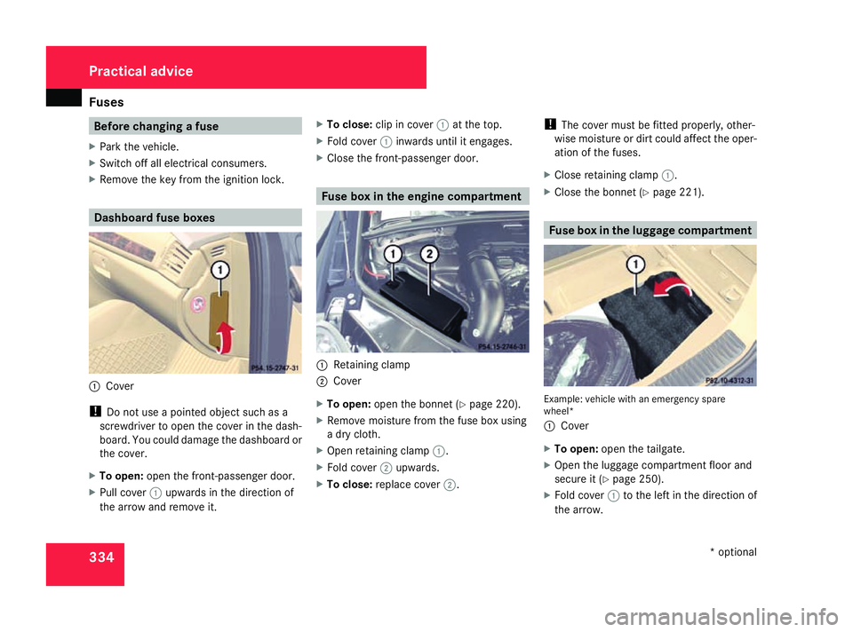
X Remove the key from the ignition lock. Dashboard fuse boxes
1
Cover
! Do not use a pointed object such as a
screwdriver to open the cover in the dash-
board. You could damage the dashboard or
the cover.
X To open: open the front-passenger door.
X Pull cover 1upwards in the direction of
the arrow and remove it. X
To close: clip in cover 1at the top.
X Fold cover 1inwards until it engages.
X Close the front-passenger door. Fuse box in the engine compartment
1
Retaining clamp
2 Cover
X To open: open the bonnet (Y page 220).
X Remove moisture from the fuse box using
a dry cloth.
X Open retaining clamp 1.
X Fold cover 2upwards.
X To close: replace cover 2. !
The cover must be fitted properly, other-
wise moisture or dirt could affect the oper-
ation of the fuses.
X Close retaining clamp 1.
X Close the bonnet (Y page 221). Fuse box in the luggage compartment
Example: vehicle with an emergency spare
wheel*
1
Cover
X To open: open the tailgate.
X Open the luggage compartment floor and
secure it (Y page 250).
X Fold cover 1to the left in the direction of
the arrow. Practical advice
* optional
251_AKB; 5; 7, en-GB
wobuchh,
Version: 2.10.6 2008-05-11T14:51:51+02:00 - Seite 334Dateiname: 6515_1825_02_buchblock.pdf; preflight
Page 354 of 373

Vehicle weights
351Tailgate opening dimensions
1
Max. headroom
2 Tailgate opening height Vehicle level
52 1
1 2
2 191 cm 204 cm
!
In vehicles with the AIRMATIC package*,
the tailgate opening dimensions may vary
depending on the selected basic setting
and current vehicle level.
Therefore, make sure that there is suffi-
cient clearance above the tailgate. Vehicle weights
The unladen weight includes the driver (68 kg), luggage (7 kg) and all fluids (fuel tank 90% full). Items of optional equipment increase the
unladen weight and reduce the maximum payload. Specific weight specifications can be found on the vehicle identification plate
(Y page 340). Short wheelbase R 280 R 350 R 350 4MATIC R 500 4MATIC
Unladen weight (in accordance with EC
directive) 2,130 kg 2,130 kg 2,180 kg 2,220 kg
Maximum permissible gross vehicle
weight 2,790 kg 2,790 kg 2,840 kg 2,880 kg
Maximum permissible front axle load 1,370 kg 1,370 kg 1,370 kg 1,370 kg
52
Values are rounded off and valid for unladen vehicles with basic equipment. Technical data
251_AKB; 5; 7, en-GB
wobuchh
,V ersion: 2.10.6
2008-05-11T14:51:51+02:00 - Seite 351 ZDateiname: 6515_1825_02_buchblock.pdf; preflight