fuse MERCEDES-BENZ R-CLASS MPV 2008 Owners Manual
[x] Cancel search | Manufacturer: MERCEDES-BENZ, Model Year: 2008, Model line: R-CLASS MPV, Model: MERCEDES-BENZ R-CLASS MPV 2008Pages: 373, PDF Size: 6.75 MB
Page 10 of 373

7
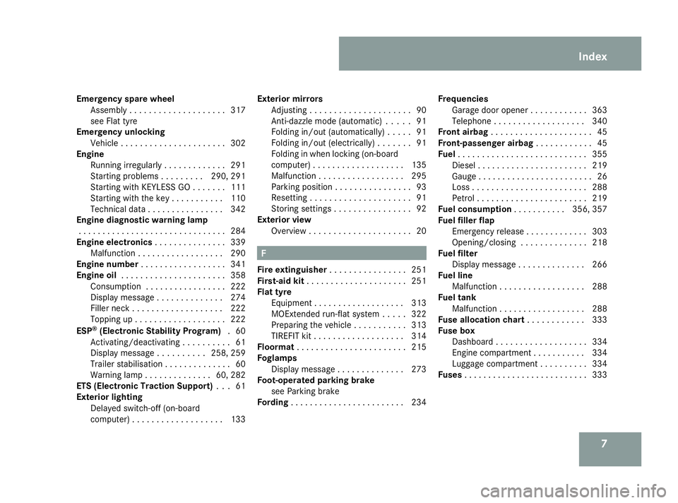
Emergency spare wheel
Assembly . . . . . . . . . . . . . . . . . . . .317
see Flat tyre
Emergency unlocking
Vehicle . . . . . . . . . . . . . . . . . . . . . .302
Engine
Running irregularl y.. . . . . . . . . . . .291
Starting problems . . . . . . . . .290, 291
Starting with KEYLESS GO . . . . . . .111
Starting with the key . . . . . . . . . . .110
Technical data . . . . . . . . . . . . . . . .342
Engine diagnostic warning lamp
. . . . . . . . . . . . . . . . . . . . . . . . . . . . . . .284
Engine electronics . . . . . . . . . . . . . ..339
Malfunction . . . . . . . . . . . . . . . . . .290
Engine number . . . . . . . . . . . . . . . . . .341
Engine oil . . . . . . . . . . . . . . . . . . . . . .358
Consumption . . . . . . . . . . . . . . . . .222
Display message . . . . . . . . . . . . . .274
Filler neck . . . . . . . . . . . . . . . . . . .222
Topping up . . . . . . . . . . . . . . . . . . .222
ESP ®
(Electronic Stability Program) .60
Activating/deactivating . . . . . . . . . .61
Display message . . . . . . . . . .258, 259
Trailer stabilisatio n.. . . . . . . . . . . . .60
Warning lamp . . . . . . . . . . . . . .60, 282
ETS (Electronic Traction Support) . ..61
Exterior lighting Delayed switch-off (on-board
computer) . . . . . . . . . . . . . . . . . . .133 Exterior mirrors
Adjusting . . . . . . . . . . . . . . . . . . . . .90
Anti-dazzle mode (automatic) . . . . .91
Folding in/out (automatically ).. . . .91
Folding in/out (electrically) . . . . . . .91
Folding in when locking (on-board
computer) . . . . . . . . . . . . . . . . . . .135
Malfunction . . . . . . . . . . . . . . . . . .295
Parking position . . . . . . . . . . . . . . . .93
Resettin g.. . . . . . . . . . . . . . . . . . . .91
Storing settings . . . . . . . . . . . . . . . .92
Exterior view
Overview . . . . . . . . . . . . . . . . . . . . .20 F
Fire extinguisher . . . . . . . . . . . . . . . .251
First-aid kit . . . . . . . . . . . . . . . . . . . . .251
Flat tyre Equipment . . . . . . . . . . . . . . . . . . .313
MOExtended run-flat system . . . . .322
Preparing the vehicle . . . . . . . . . . .313
TIREFIT kit . . . . . . . . . . . . . . . . . . .314
Floormat . . . . . . . . . . . . . . . . . . . . . . .215
Foglamps Display message . . . . . . . . . . . . . .273
Foot-operated parking brake
see Parking brake
Fording . . . . . . . . . . . . . . . . . . . . . . . .234 Frequencies
Garage door opene r.. . . . . . . . . . .363
Telephone . . . . . . . . . . . . . . . . . . .340
Front airbag . . . . . . . . . . . . . . . . . . . . .45
Front-passenger airbag . . . . . . . . . . ..45
Fuel . . . . . . . . . . . . . . . . . . . . . . . . . . .355
Diese l.. . . . . . . . . . . . . . . . . . . . . .219
Gauge . . . . . . . . . . . . . . . . . . . . . . . .26
Loss . . . . . . . . . . . . . . . . . . . . . . . .288
Petrol . . . . . . . . . . . . . . . . . . . . . . .219
Fuel consumption . . . . . . . . . ..356, 357
Fuel filler flap Emergency release . . . . . . . . . . . . .303
Opening/closing . . . . . . . . . . . . . .218
Fuel filter
Display message . . . . . . . . . . . . . .266
Fuel line
Malfunction . . . . . . . . . . . . . . . . . .288
Fuel tank
Malfunction . . . . . . . . . . . . . . . . . .288
Fuse allocation chart . . . . . . . . . . ..333
Fuse box Dashboard . . . . . . . . . . . . . . . . . . .334
Engine compartment . . . . . . . . . . .334
Luggage compartment . . . . . . . . . .334
Fuses . . . . . . . . . . . . . . . . . . . . . . . . . .333 Index
251_AKB; 5; 7, en-GB
wobuchh,
Version: 2.10.6 2008-05-11T14:51:51+02:00 - Seite 7Dateiname: 6515_1825_02_buchblock.pdf; preflight
Page 183 of 373

Sliding sunroof
180
Lowering and closing X
To lower manually: pull the switch in the
direction of arrow 2and hold it until the
sliding/tilting sunroof is in the desired posi-
tion.
X To lower fully: pull the switch briefly
beyond the pressure point in the direction
of arrow 2and release it.
X To stop: press or pull the switch in any
direction.
Rain closing feature* The sliding/tilting sunroof closes automati-
cally:
R if it starts to rain
R at extreme outside temperatures
R after 12 hours
R if there is a malfunction in the power supply
The rear of the sliding/tilting sunroof is then
raised in order to ventilate the interior of the
vehicle.
i The sliding/tilting sunroof is opened
slightly again if it is obstructed while being
closed by the rain closing feature. The rain
closing feature is then deactivated. i
The sliding/tilting sunroof does not close
if:
R it is raised at the rear
R it is blocked
R no rain is falling on the windscreen (e.g.
because the vehicle is under a bridge or
in a carport)
Opening and closing the cover The cover functions as a sunblind. When you
open the sliding/tilting sunroof, the cover
moves back with it.
When the sliding/tilting sunroof is closed or
raised at the rear, you can open or close the
cover manually.Resetting the sliding/tilting sunroof Reset the sliding/tilting sunroof if it does not
open smoothly, or if the battery has been dis-
connected or has become discharged.
X
Make sure that the key is in position 0in
the ignition lock.
X Remove the fuse for the sliding/tilting sun-
roof in the main fuse box (Y page 334).
i The fuse allocation chart can be found in
the vehicle tool kit (Y page 252).
X Reinsert the fuse.
X Make sure that the key is in position 2in
the ignition lock.
X The sliding/tilting sunroof is raised fully at
the rear.
X Keep the switch pressed for an additional
second.
X Make sure that the sliding/tilting sunroof
can be opened or closed fully again
(Y page 179).
X If this is not the case, consult a qualified
specialist workshop. Controls
* optional
251_AKB; 5; 7, en-GB
wobuchh,
Version: 2.10.6 2008-05-11T14:51:51+02:00 - Seite 180Dateiname: 6515_1825_02_buchblock.pdf; preflight
Page 186 of 373

Loading and stowing
183
Opening
X
To open manually: press the switch in the
direction of arrow 1or3 until the roller
sunblinds have moved to the desired posi-
tion.
X To open fully: briefly press the switch
beyond the pressure point in the direction
of arrow 1or3.
X To stop: press or pull the switch in any
direction.
Closing
X Pull the switch in the direction of
arrow 2until the roller sunblinds have
moved to the desired position.
Resetting the panorama sliding sunroof
and the roller sunblinds Reset the panorama sliding sunroof and the
roller sunblinds if the panorama sliding sun-
roof does not open smoothly, or if the battery
has been disconnected or discharged.
X
Make sure that the key is in position 0in
the ignition lock.
X Remove the fuse for the panorama sliding
sunroof in the main fuse box
(Y page 334). i
The fuse allocation chart can be found in
the vehicle tool kit (Y page 252).
X Reinsert the fuse.
X Make sure that the key is in position 2in
the ignition lock.
X Close the roller sunblinds fully.
X Keep the switch pressed for an additional
second.
X Open the roller sunblinds fully.
X Keep the switch pressed for an additional
second.
X Raise the panorama sliding sunroof fully.
X Keep the switch pressed for an additional
second.
X Close the panorama sliding sunroof fully.
X Keep the switch pressed for an additional
second.
X Check that the panorama sliding sunroof
can be opened fully again (Y page 181).
X If this is not the case, consult a qualified
specialist workshop. Loading and stowing
Cup holder
G
Risk of injury
Keep the cup holder closed while the vehi-
cle is in motion. Otherwise, vehicle occu-
pants could be injured by objects being
thrown around if you:
R brake sharply
R change direction suddenly
R are involved in an accident
Only use the cup holders for containers of
a suitable size and which have lids. Other-
wise, the drinks could spill.
Cup holders should not be used for hot
drinks. Otherwise, you may scald yourself. Controls
251_AKB; 5; 7, en-GB
wobuchh,
Version: 2.10.6 2008-05-11T14:51:51+02:00 - Seite 183 ZDateiname: 6515_1825_02_buchblock.pdf; preflight
Page 209 of 373

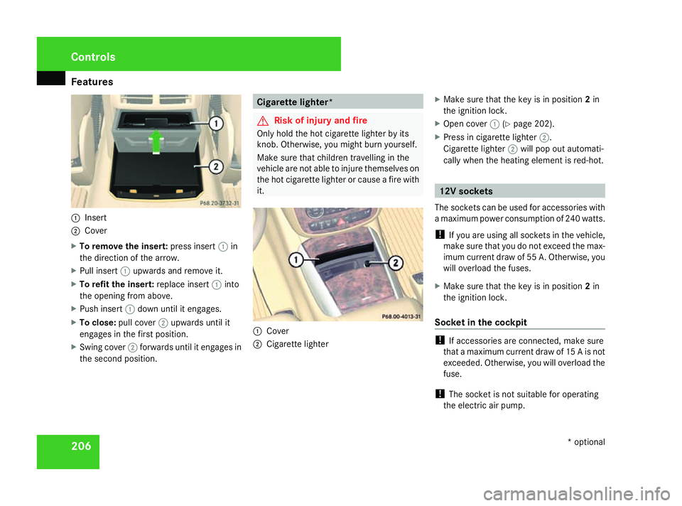
Features
2061
Insert
2 Cover
X To remove the insert: press insert1in
the direction of the arrow.
X Pull insert 1upwards and remove it.
X To refit the insert: replace insert1into
the opening from above.
X Push insert 1down until it engages.
X To close: pull cover 2upwards until it
engages in the first position.
X Swing cover 2forwards until it engages in
the second position. Cigarette lighter*
G
Risk of injury and fire
Only hold the hot cigarette lighter by its
knob. Otherwise, you might burn yourself.
Make sure that children travelling in the
vehicle are not able to injure themselves on
the hot cigarette lighter or cause a fire with
it. 1
Cover
2 Cigarette lighter X
Make sure that the key is in position 2in
the ignition lock.
X Open cover 1(Ypage 202).
X Press in cigarette lighter 2.
Cigarette lighter 2will pop out automati-
cally when the heating element is red-hot. 12V sockets
The sockets can be used for accessories with
a maximum power consumption of 240 watts.
! If you are using all sockets in the vehicle,
make sure that you do not exceed the max-
imum current draw of 55 A. Otherwise, you
will overload the fuses.
X Make sure that the key is in position 2in
the ignition lock.
Socket in the cockpit !
If accessories are connected, make sure
that a maximum current draw of 15 A is not
exceeded. Otherwise, you will overload the
fuse.
! The socket is not suitable for operating
the electric air pump. Controls
* optional
251_AKB; 5; 7, en-GB
wobuchh,
Version: 2.10.6
2008-05-11T14:51:51+02:00 - Seite 206 Dateiname: 6515_1825_02_buchblock.pdf; preflight
Page 210 of 373

Features
2071
Cover
2 Socket protective cap
X Open cover 1(Ypage 202).
X Remove protective cap 2from the socket.
i On vehicles with the smoker's package*,
a cigarette lighter is fitted instead of the
socket (Y page 206).
Socket in the 2nd row of seats !
If accessories are connected, make sure
that a maximum current draw of 20 A is not
exceeded. Otherwise, you will overload the
fuse. X
Fold up the socket cover.
i You can also use the socket when the
ignition is switched off. An emergency cut-
out ensures that the on-board voltage does
not drop too low. If the on-board voltage is
too low, the power to the sockets is auto-
matically cut. This ensures that there is
sufficient power to start the engine.
Socket in the luggage compartment !
If accessories are connected, make sure
that a maximum current draw of 20 A is not
exceeded. Otherwise, you will overload the
fuse. The socket is located in the luggage compart-
ment on the right-hand side trim.
X
Fold up the socket cover.
i You can also use the socket when the
ignition is switched off. An emergency cut-
out ensures that the on-board voltage does
not drop too low. If the on-board voltage is
too low, the power to the sockets is auto-
matically cut. This ensures that there is
sufficient power to start the engine. Controls
* optional
251_AKB; 5; 7, en-GB
wobuchh, Version: 2.10.6 2008-05-11T14:51:51+02:00 - Seite 207 ZDateiname: 6515_1825_02_buchblock.pdf; preflight
Page 246 of 373

Care
243Exceeding the service due date
One of the following messages appears in the
multi-function display:
Service A .. days overdue
Service A overdue by .. km
You will also hear a warning tone.
A qualified specialist workshop, e.g. a
Mercedes-Benz Service Centre, will reset the
ASSYST PLUS service interval indicator after
the necessary service work has been carried
out.
i If you fail to have the service performed
by the specified date, you may be violating
applicable laws. Your warranty may be inva-
lidated and goodwill settlements may be
refused. Calling up the service due date
Use the buttons on the multi-function steer-
ing wheel.
X Switch on the ignition.
X Press èorÿ to select the Basic
display menu (Y page 125).
X Press the jork button to select the
service information.
The 9 service symbol and the service
due date are displayed. Care
Notes on care
Regular and proper care maintains the value
of your vehicle.
i It is advisable to use Mercedes-Benz care
products.
Scratches, corrosive deposits, areas affected
by corrosion and damage caused by inade-
quate care cannot always be completely
repaired. In such cases, visit a qualified spe-
cialist workshop immediately, e.g. a
Mercedes-Benz Service Centre.
Repair damage caused by loose chippings
and remove the following substances imme-
diately, whilst avoiding rubbing too hard:
R Soak insect remains with insect remover
and rinse off afterwards.
R Soak bird droppings with water and rinse
off afterwards.
R Remove tree resin, oils, fuels and greases
by rubbing gently with a cloth soaked in
petroleum ether or lighter fluid.
R Use silicone remover to remove wax.
R Use tar remover to remove tar stains. Operation
251_AKB; 5; 7, en-GB
wobuchh,
Version: 2.10.6 2008-05-11T14:51:51+02:00 - Seite 243 ZDateiname: 6515_1825_02_buchblock.pdf; preflight
Page 252 of 373

249
Where will I find...?
...........................250
Display messages ............................. 255
Troubleshooting ................................ 278
Locking/unlocking in an emer-
gency ................................................. 302
Resetting triggered NECK-PRO
head restraints .................................. 304
Changing the batteries .....................304
Changing the bulbs ...........................306
Replacing the wiper blades ..............311
Flat tyre ............................................. 313
Battery ............................................... 323
Jump-starting .................................... 329
Towing and tow-starting ..................330
Fuses .................................................. 333 Practical advice
251_AKB; 5; 7, en-GB
wobuchh,
Version: 2.10.6
2008-05-11T14:51:51+02:00 - Seite 249 Dateiname: 6515_1825_02_buchblock.pdf; preflight
Page 255 of 373

Where will I find...?
252 Vehicle tool kit, jack, TIREFIT kit and
emergency spare wheel*
The vehicle tool kit, jack, TIREFIT kit and
emergency spare wheel* are in the stowage
compartment under the luggage compart-
ment floor. G
Risk of injury
The jack is designed only to raise and hold
the vehicle for a short time while a wheel
is being changed.
You must use stands if you are carrying out
work on the vehicle.
Make sure that the jack is placed on a firm,
non-slip and level surface. Do not use
wooden blocks or similar objects as a jack
underlay. Otherwise, the jack will not be
able to achieve its load-bearing capacity
due to the restricted height.
Do not start the engine at any time while a
wheel is being changed.
Do not lie under the vehicle when it is being
supported by the jack. If you do not raise
the vehicle as described, it could slip off the
jack (e.g. if the engine is started or a door
or the tailgate is opened or closed) and you
could be seriously injured. X
Open the tailgate.
X Open the luggage compartment floor
(Y page 250).
! If the luggage compartment cover* is fit-
ted, roll it open fully.
Only for luggage compartment covers* fit-
ted behind the 3rd row of seats:
Fold forwards the section of the luggage
compartment cover* that is still protrud-
ing. Otherwise the strap of the retaining
hook may damage the luggage compart-
ment cover*.
Vehicles with a TIREFIT kit i
Depending on the date of production of
the vehicle, the appearance and stowage
location of the jack and of the other tools
may differ from those illustrated. Example
1
Ball coupling of the trailer tow hitch*
2 Folding wheel chock
3 Jack, ratchet ring spanner
4 TIREFIT kit 30
5 Electric air pump 30
6 Fuse allocation chart
7 Wheel wrench
8 Towing eye
9 Centring pin
Vehicles with an emergency spare
wheel* i
Depending on the date of production of
the vehicle, the appearance and stowage
30 Not on vehicles with MOExtended run-flat system. Practical advice
* optional
251_AKB; 5; 7, en-GB
wobuchh,
Version: 2.10.6 2008-05-11T14:51:51+02:00 - Seite 252Dateiname: 6515_1825_02_buchblock.pdf; preflight
Page 256 of 373

Where will I find...?
253
location of the jack and of the other tools
may differ from those illustrated.
Example
1
Tool holder
2 Wheel wrench
3 Electric air pump
4 Instructions on the installation position of
the tool holder
5 Fuse allocation chart
6 Jack, ratchet ring spanner
7 Centring pin
8 Folding wheel chock
9 Towing eye
a Wheel bolts
b Ball coupling of the trailer tow hitch*
c Emergency spare wheel* Removing the emergency spare wheel*
X
Remove the jack from the tool holder
(Y page 252). 1
Retaining screw
2 Emergency spare wheel*
3 Tool holder
X Turn retaining screw 1anticlockwise and
out of tool holder 3and remove it.
i If retaining screw 1does not come out
immediately, turn tool holder 3anticlock-
wise a little.
Retaining screw 1should then unscrew
with ease. X
Turn tool holder 3approximately 180°, so
that the electrical air pump points back-
wards (Y page 252).
X Remove tool holder 3from emergency
spare wheel* 2.
X Remove emergency spare wheel* 2from
the emergency spare wheel well.
Stowing the emergency spare wheel*
X Remove the warning triangle from the
emergency spare wheel well (Y page 250). 1
Guides
In the spare wheel well, there are two guides
1 to keep the emergency spare wheel* in
place. Practical advice
* optional
251_AKB; 5; 7, en-GB
wobuchh
, Version: 2.10.6 2008-05-11T14:51:51+02:00 - Seite 253 ZDateiname: 6515_1825_02_buchblock.pdf; preflight
Page 294 of 373

Troubleshooting
291Problem Possible cause/consequence Suggested solutions
Vehicles with a petrol engine:
The engine is not running
smoothly and is misfiring. There is a malfunction in the
engine electronics or a mechani-
cal component of the engine con-
trol unit. X
Only depress the accelerator pedal slightly.
X Have the cause rectified immediately at a qualified specialist work-
shop.
Otherwise, non-combusted fuel may get into the catalytic converter
and damage it. A coolant temperature of over
120 °C is displayed. You also
hear a warning signal. The coolant level is too low. The
coolant is too hot and the engine
is no longer being cooled suffi-
ciently. X
Stop as soon as possible and allow the engine and the coolant to
cool down.
X Check the coolant level (Y page 223). Observe the warning notes
as you do so and top up the coolant if necessary. If the coolant level is correct, the
radiator fan may be faulty. The
coolant is too hot and the engine
is no longer being cooled suffi-
ciently. X
If the coolant temperature is less than 120 °C, you can continue
driving to the nearest qualified specialist workshop.
X Avoid heavy loads on the engine as you do so, e.g. driving on
mountain roads and stop/start driving. The engine does not switch off. The ignition lock is faulty. X
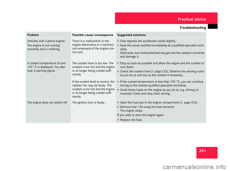
Open the fuse box in the engine compartment ( Ypage 334).
X Remove fuse 120 using the fuse extractor.
The engine stops.
If you wish to start the engine again:
X Replace the fuse. Practical advice
251_AKB; 5; 7, en-GB
wobuchh
,V ersion: 2.10.6
2008-05-11T14:51:51+02:00 - Seite 291 ZDateiname: 6515_1825_02_buchblock.pdf; preflight