load capacity MERCEDES-BENZ S CLASS 2010 Owners Manual
[x] Cancel search | Manufacturer: MERCEDES-BENZ, Model Year: 2010, Model line: S CLASS, Model: MERCEDES-BENZ S CLASS 2010Pages: 548, PDF Size: 11.45 MB
Page 420 of 548

This is the maximum permissible tire inflation
pressure \000F for the tire.
Always follow the recommended tire inflation
pressure (Y page 411) for proper tire
inflation.
Loading the vehicle
Two labels on your vehicle show how much
weight it may properly carry.
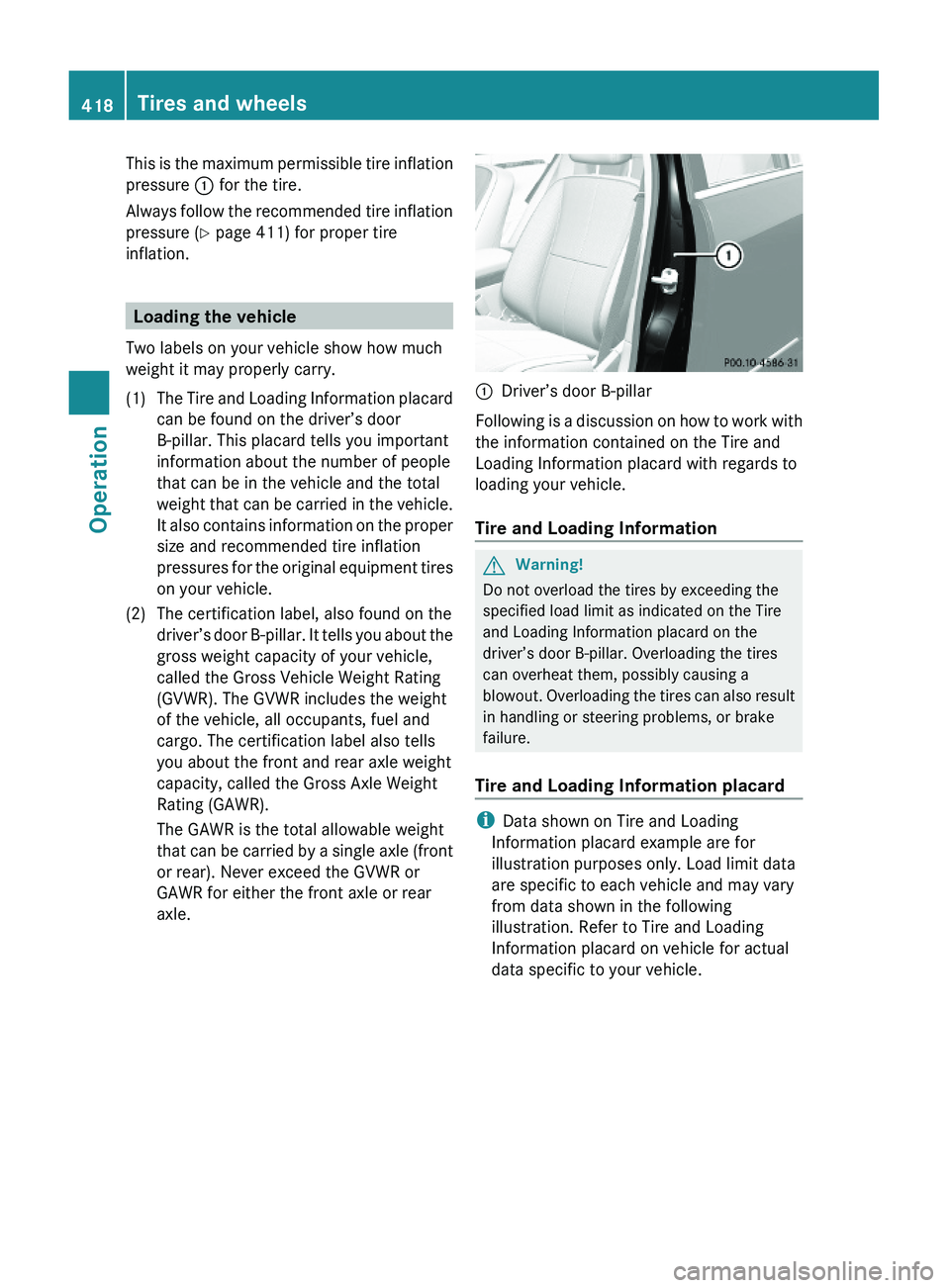
(1)The Tire and Loading Information placard
can be found on the driver’s door
B-pillar. This placard tells you important
information about the number of people
that can be in the vehicle and the total
weight that can be carried in the vehicle.
It also contains information on the proper
size and recommended tire inflation
pressures for the original equipment tires
on your vehicle.
(2)The certification label, also found on the
driver’s door B-pillar. It tells you about the
gross weight capacity of your vehicle,
called the Gross Vehicle Weight Rating
(GVWR). The GVWR includes the weight
of the vehicle, all occupants, fuel and
cargo. The certification label also tells
you about the front and rear axle weight
capacity, called the Gross Axle Weight
Rating (GAWR).
The GAWR is the total allowable weight
that can be carried by a single axle (front
or rear). Never exceed the GVWR or
GAWR for either the front axle or rear
axle.
\000FDriver’s door B-pillar
Following is a discussion on how to work with
the information contained on the Tire and
Loading Information placard with regards to
loading your vehicle.
Tire and Loading Information
GWarning!
Do not overload the tires by exceeding the
specified load limit as indicated on the Tire
and Loading Information placard on the
driver’s door B-pillar. Overloading the tires
can overheat them, possibly causing a
blowout. Overloading the tires can also result
in handling or steering problems, or brake
failure.
Tire and Loading Information placard
iData shown on Tire and Loading
Information placard example are for
illustration purposes only. Load limit data
are specific to each vehicle and may vary
from data shown in the following
illustration. Refer to Tire and Loading
Information placard on vehicle for actual
data specific to your vehicle.
418Tires and wheelsOperation
221_AKB; 6; 20, en-USd2ugruen,Version: 2.11.8.12009-09-24T13:28:17+02:00 - Seite 418
Page 421 of 548

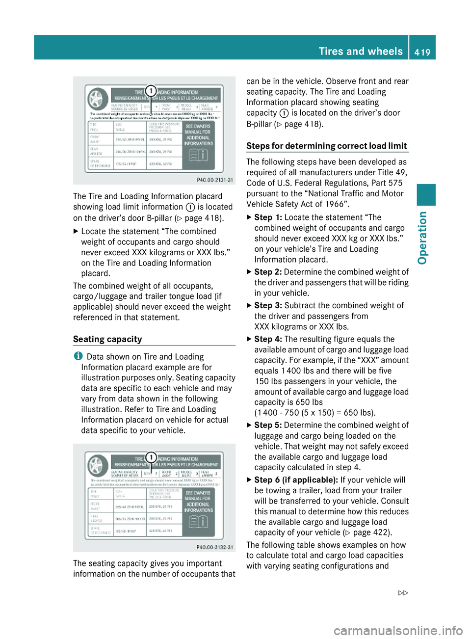
The Tire and Loading Information placard
showing load limit information \000F is located
on the driver’s door B-pillar (Y page 418).
XLocate the statement “The combined
weight of occupants and cargo should
never exceed XXX kilograms or XXX lbs.”
on the Tire and Loading Information
placard.
The combined weight of all occupants,
cargo/luggage and trailer tongue load (if
applicable) should never exceed the weight
referenced in that statement.
Seating capacity
iData shown on Tire and Loading
Information placard example are for
illustration purposes only. Seating capacity
data are specific to each vehicle and may
vary from data shown in the following
illustration. Refer to Tire and Loading
Information placard on vehicle for actual
data specific to your vehicle.
The seating capacity gives you important
information on the number of occupants that
can be in the vehicle. Observe front and rear
seating capacity. The Tire and Loading
Information placard showing seating
capacity \000F is located on the driver’s door
B-pillar (Y page 418).
Steps for determining correct load limit
The following steps have been developed as
required of all manufacturers under Title 49,
Code of U.S. Federal Regulations, Part 575
pursuant to the “National Traffic and Motor
Vehicle Safety Act of 1966”.
XStep 1: Locate the statement “The
combined weight of occupants and cargo
should never exceed XXX kg or XXX lbs.”
on your vehicle’s Tire and Loading
Information placard.
XStep 2: Determine the combined weight of
the driver and passengers that will be riding
in your vehicle.
XStep 3: Subtract the combined weight of
the driver and passengers from
XXX kilograms or XXX lbs.
XStep 4: The resulting figure equals the
available amount of cargo and luggage load
capacity. For example, if the “XXX” amount
equals 1 400 lbs and there will be five
150 lbs passengers in your vehicle, the
amount of available cargo and luggage load
capacity is 650 lbs
(1 400 - 750 (5 x 150) = 650 lbs).
XStep 5: Determine the combined weight of
luggage and cargo being loaded on the
vehicle. That weight may not safely exceed
the available cargo and luggage load
capacity calculated in step 4.
XStep 6 (if applicable): If your vehicle will
be towing a trailer, load from your trailer
will be transferred to your vehicle. Consult
this manual to determine how this reduces
the available cargo and luggage load
capacity of your vehicle (Y page 422).
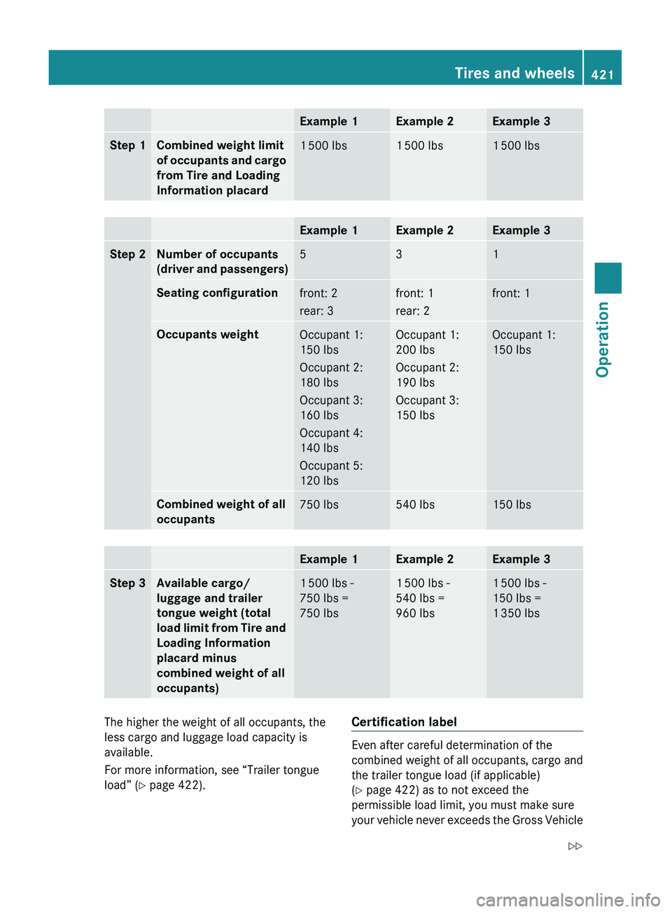
The following table shows examples on how
to calculate total and cargo load capacities
with varying seating configurations and
Tires and wheels419Operation221_AKB; 6; 20, en-USd2ugruen,Version: 2.11.8.12009-09-24T13:28:17+02:00 - Seite 419Z
Page 423 of 548

Example 1Example 2Example 3Step 1Combined weight limit
of occupants and cargo
from Tire and Loading
Information placard1 500 lbs1 500 lbs1 500 lbsExample 1Example 2Example 3Step 2Number of occupants
(driver and passengers)531Seating configurationfront: 2
rear: 3front: 1
rear: 2front: 1Occupants weightOccupant 1:
150 lbs
Occupant 2:
180 lbs
Occupant 3:
160 lbs
Occupant 4:
140 lbs
Occupant 5:
120 lbsOccupant 1:
200 lbs
Occupant 2:
190 lbs
Occupant 3:
150 lbsOccupant 1:
150 lbsCombined weight of all
occupants750 lbs540 lbs150 lbsExample 1Example 2Example 3Step 3Available cargo/
luggage and trailer
tongue weight (total
load limit from Tire and
Loading Information
placard minus
combined weight of all
occupants)1 500 lbs -
750 lbs =
750 lbs1 500 lbs -
540 lbs =
960 lbs1 500 lbs -
150 lbs =
1 350 lbsThe higher the weight of all occupants, the
less cargo and luggage load capacity is
available.
For more information, see “Trailer tongue
load” ( Y page 422).Certification label
Even after careful determination of the
combined weight of all occupants, cargo and
the trailer tongue load (if applicable)
( Y page 422) as to not exceed the
permissible load limit, you must make sure
your vehicle never exceeds the Gross Vehicle
Tires and wheels421Operation221_AKB; 6; 20, en-USd2ugruen,Version: 2.11.8.12009-09-24T13:28:17+02:00 - Seite 421Z
Page 434 of 548

Sidewall
The portion of a tire between the tread and
the bead.
TIN (Tire Identification Number)
Unique identifier which facilitates efforts by
tire manufacturers to notify purchasers in
recall situations or other safety matters
concerning tires and gives purchasers the
means to easily identify such tires. The TIN is
comprised of “Manufacturer’s identification
mark”, “Tire size”, “Tire type code” and “Date
of manufacture”.
Tire ply composition and material used
This indicates the number of plies or the
number of layers of rubber-coated fabric in
the tire tread and sidewall. Tire
manufacturers also must indicate the ply
materials in the tire and sidewall, which
include steel, nylon, polyester, and others.
Tire speed rating
Part of tire designation (speed symbol);
indicates the speed range for which a tire is
approved.
Total load limit
Rated cargo and luggage load plus
68 kilograms (150 lb) times the vehicle’s
designated seating capacity.
Traction
The adhesive friction of a tire on a surface on
which it moves. The amount of grip provided.
Tread
The portion of a tire that comes into contact
with the road.
Treadwear indicators
Narrow bands, sometimes called “wear bars”
that show across the tread of a tire when only
1 / 16 in (1.6 mm) of tread remains.
Uniform Tire Quality Grading Standards
A tire information system that provides
consumers with ratings for a tire’s traction,
temperature and treadwear. Ratings are
determined by tire manufacturers using U.S.
government testing procedures. The ratings
are molded into the sidewall of the tire.
Vehicle maximum load on the tire
Load on an individual tire that is determined
by distributing to each axle its share of the
maximum loaded vehicle weight and dividing
it by two.
Winter driving
General information
Have your vehicle winterized at an authorized
Mercedes-Benz Center.
Winter tires
GWarning!
Winter tires with a tread depth of less than
1 / 6 in (4 mm) must be replaced. They are no
longer suitable for winter operation.
GWarning!
If you use your spare wheel when winter tires
are fitted on the other wheels, be aware that
the difference in tire characteristics may very
well impair turning stability and that overall
driving stability may be reduced. Adapt your
driving style accordingly.
Have the spare wheel replaced by a regular
road wheel with a winter tire at the nearest
authorized Mercedes-Benz Center.
432Winter drivingOperation
221_AKB; 6; 20, en-USd2ugruen,Version: 2.11.8.12009-09-24T13:28:17+02:00 - Seite 432
Page 511 of 548

Open doors only when conditions are safe
to do so.XVehicles with KEYLESS-GO: Remove the
KEYLESS-GO start/stop button from the
starter switch.XHave any passenger exit the vehicle at a
safe distance from the roadway. Open
doors only when conditions are safe to do
so.
Mounting the spare wheel
Introduction
XPrepare the vehicle as described
( Y page 508).XTake the following out of the vehicle:
R spare wheel
R jack
R vehicle tool kit
For information on where to find the
respective items, see “Where will I find ...?”
( Y page 450) and ( Y page 451).
i Vehicles without spare wheel are not
factory-equipped with the tools required for
a wheel change such as a jack or a wheel
wrench. Some tools required for a wheel
change are specific to your vehicle.
Contact an authorized Mercedes-Benz
Center to obtain the tools approved for
your vehicle. This section describes the
wheel change using the tools approved and
recommended for your vehicle.
Lifting the vehicle
GWarning!
When jacking up the vehicle, only use the jack
which has been specifically approved by
Mercedes-Benz for your vehicle.
The jack is designed exclusively for jacking up
the vehicle at the jack take-up brackets built
into both sides of the vehicle. Make sure the
jack arm is fully seated in the jack take-up
bracket. The jack must always be vertical
when in use, especially on inclines or
declines.
The jack is intended only for lifting the vehicle
briefly for wheel changes. It is not suited for
performing maintenance work under the
vehicle. To help avoid personal injury, use the
jack only to lift the vehicle during a wheel
change.
Never get beneath the vehicle while it is
supported by the jack. Keep hands and feet
away from the area under the lifted vehicle.
Always lower the vehicle onto sufficient
capacity jackstands before working under the
vehicle.
Always make sure the electronic parking
brake is engaged. In addition, block the
wheels with wheel chocks or other sizeable
objects before raising the vehicle with the
jack. Do not disengage the electronic parking
brake while the vehicle is raised.
Make sure that the ground on which the
vehicle is standing and where you place the
jack is solid, level and not slippery. If
necessary, use a large underlay. On slippery
surfaces, such as tiled floors, you should use
a non-slip underlay, for example a rubber mat.
Do not use wooden blocks or similar objects
to support the jack. Otherwise the jack may
not be able to achieve its load-bearing
capacity if it is not at its full height.
Never start the engine when the vehicle is
raised.
Also observe the notes on the jack.XPrevent the vehicle from rolling away by
blocking wheels with wheel chocks or other
sizeable objects.
When your vehicle is equipped with a wheel
chock, it is included with the vehicle tool kit
( Y page 450). For information on setting up
the collapsible wheel chock, see
( Y page 450).Flat tire509Practical hints221_AKB; 6; 20, en-USd2ugruen,Version: 2.11.8.12009-09-24T13:28:17+02:00 - Seite 509Z