ECU MERCEDES-BENZ S-Class COUPE 2016 C217 Manual PDF
[x] Cancel search | Manufacturer: MERCEDES-BENZ, Model Year: 2016, Model line: S-Class COUPE, Model: MERCEDES-BENZ S-Class COUPE 2016 C217Pages: 410, PDF Size: 8.62 MB
Page 356 of 410
Towing and tow-starting
Important safety notes
GWARNING
Functions relevant to safety are restricted or
no longer available if:
Rthe engine is not running.
Rthe brake system or the power steering is
malfunctioning.
Rthere is a malfunction in the voltage supply or the vehicle's electrical system.
If your vehicle is being towed, much more
force may be necessary to steer or brake.
There is a risk of an accident.
In such cases, use a tow bar. Before towing,
make sure that the steering moves freely.
GWARNING
You can no longer steer the vehicle if the
steering wheel lock has been engaged. There
is a risk of an accident.
Always switch off the ignition when towing the
vehicle with a tow cable or a tow bar.
GWARNING
When towing or tow-starting another vehicle
and its weight is greater than the permissible
gross weight of your vehicle, the:
Rthe towing eye could detach itself
Rthe vehicle/trailer combination could roll-
over.
There is a risk of an accident.
When towing or tow-starting another vehicle,
its weight should not be greater than the per- missible gross weight of your vehicle.
Information on your vehicle's gross vehicle
weight rating can be found on the vehicle
identification plate (
Ypage 399).
!When COLLISION PREVENTION ASSIST
PLUS, DISTRONIC PLUS or the HOLD func-
tion is activated, the vehicle brakes auto-
matically in certain situations. To avoid
damage to the vehicle, deactivate these
systems in the following or similar situa-
tions:
Rwhen towing the vehicle
Rin the car wash
!Make sure that the electric parking brake
is released. If the electric parking brake is
faulty, visit a qualified specialist workshop.
!Secure the tow rope or tow bar to the
towing eye only. Otherwise, the vehicle
could become damaged.
!Do not use the towing eyes for recovery
purposes as this could damage the vehicle.
If in doubt, recover the veh icle w
ith a crane.
!When towing, pull away slowly and
smoothly. If the tractive power is too high,
the vehicles could be damaged.
!Shift the automatic transmission to Nand
do not open the driver's or front passeng-
er's door during towing. The automatic
transmission may otherwise shift to posi-
tion P, which could damage the transmis-
sion.
!Do not tow with sling-type equipment.
This could damage the vehicle.
!The vehicle can be towed a maximum of
30 miles (50km). The towing speed of
30 mph (50 km/h) must not be exceeded.
If the vehicle has to be towed more than
30 miles (50km), the entire vehicle must be raised and transported.
It is better to have the vehicle transported
than to have it towed away.
If the vehicle has suffered transmission dam-
age, have it transported on a transporter or
trailer.
The automatic transmission must be in posi-
tion Nwhen the vehicle is being towed.
354Towing and tow-starting
Breakdown assistance
Page 358 of 410
tion switch, the hazard warning lamp starts
flashing again.
Towing the vehicle with the rear axle
raised
Only vehicles without 4MATIC can be
towed with the rear axle raised.
!The ignition must be switched off if you
are towing the vehicle with the rear axle
raised. Intervention by ESP
®could other-
wise damage the brake system.
!Vehicles with 4MATIC must not be towed
with either the front or the rear axle raised,
as doing so will damage the transmission.
!Vehicles with automatic transmission
must not be towed with the rear axle raised.
The vehicle/trailer combination may oth-
erwise swerve or even roll over.
Transporting the vehicle
!
You may only secure the vehicle by the
wheels, not by parts of the vehicle such as axle or steering components. Otherwise,
the vehicle could be damaged.
The towing eye can be used to pull the vehicle
onto a trailer or transporter for transporting
purposes.
XTurn the SmartKey to position 2in the igni-
tion lock.
XShift the automatic transmission to posi-
tion N.
As soon as the vehicle has been loaded:
XPrevent the vehicle from rolling away by
applying the electric parking brake.
XShift the automatic transmission to posi-
tion P.
XTurn the SmartKey to position 0in the igni-
tion lock and remove it.
XSecure the vehicle.
Notes on 4MATIC vehicles
!
Vehicles with 4MATIC must not be towed
with either the front or the rear axle raised,
as doing so will damage the transmission.
Vehicles with 4MATIC may either be towed
away with both axles on the ground or be loa- ded up and transported.
If the vehicle's transmission, front, or rear
axle is damaged, have the vehicle transported
on a truck or trailer.
In the event of damage to the electrical
system: if the battery is defective, the auto-
matic transmission will be locked in position
P . To shift the automatic transmission to posi-
tion N, you must provide power to the vehi-
cle's electrical system in the same way as
when jump-starting (
Ypage 351).
Have the vehicle transported on a transporter
or trailer.
Tow-starting (emergency engine
starting)
!
Vehicles with automatic transmission
must not be tow-started. You could other-
wise damage the automatic transmission.
iInformation on "Jump-starting"
(
Ypage 351).
Fuses
Important safety notes
GWARNING
If you manipulate or bridge a faulty fuse or if
you replace it with a fuse with a higher amper- age, the electric cables could be overloaded.
This could result in a fire. There is a risk of an
accident and injury.
Always replace faulty fuses with the specified
new fuses having the correct amperage.
Blown fuses must be replaced with fuses of
the same rating, which you can recognize by
356Fuses
Breakdown assistance
Page 359 of 410
the color and value. The fuse ratings are listed
in the fuse allocation chart.
The fuse allocation chart is on the fuse box in
the trunk (
Ypage 358).
If a newly inserted fuse also blows, have the
cause traced and rectified at a qualified spe-
cialist workshop, e.g. an authorized
Mercedes-Benz Center.
!Only use fuses that have been approved
for Mercedes-Benz vehicles and which
have the correct fuse rating for the system
concerned. Otherwise, components or sys-
tems could be damaged.
The fuses in your vehicle serve to close down
faulty circuits. If a fuse blows, all the compo-
nents on the circuit and their functions stop
operating.
Before changing a fuse
XSecure the vehicle against rolling away
(
Ypage 170).
XSwitch off all electrical consumers.
XMake sure that the ignition is switched off
(
Ypage 151).
or
XWhen using the SmartKey, turn the Smart-
Key to position 0in the ignition lock and
remove it (
Ypage 151).
All indicator lamps in the instrument cluster
must be off.
The fuses are located in various fuse boxes:
RFuse box on the driver's side of the dash-
board
RFuse box in the front-passenger footwell
RFuse box in the engine compartment on the left-hand side of the vehicle, when viewed
in the direction of travel
RFuse box in the trunk on the right-hand side
of the vehicle, when viewed in the direction
of travel
Dashboard fuse box
!
Do not use a pointed object such as a
screwdriver to open the cover in the dash-
board. You could damage the dashboard or
the cover.
!Make sure that no moisture can enter the
fuse box when the cover is open.
!When closing the cover, make sure that it
is lying correctly on the fuse box. Moisture
seeping in or dirt could otherwise impair
the operation of the fuses.
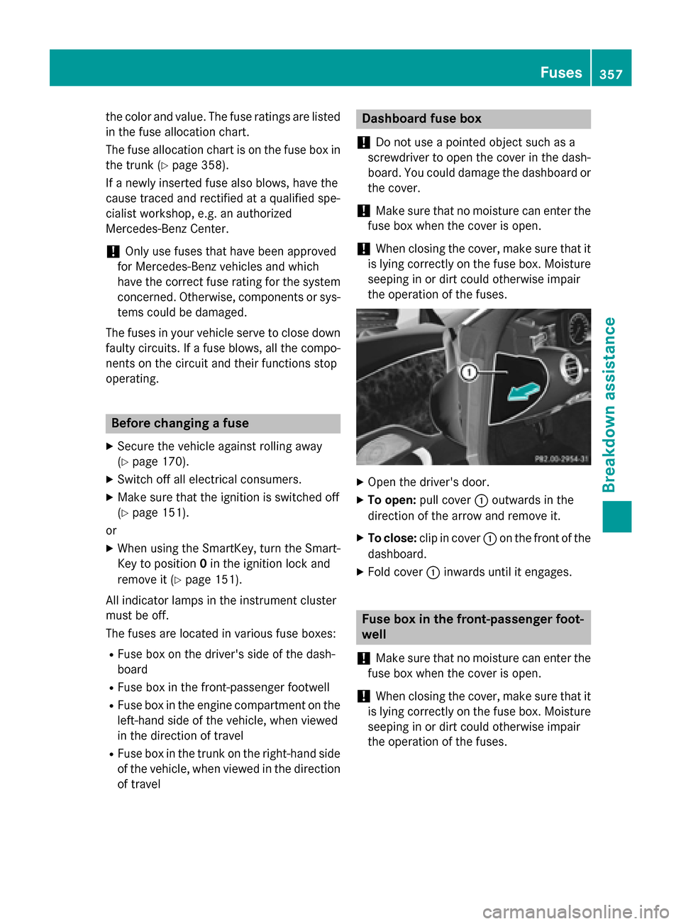
XOpen the driver's door.
XTo open: pull cover :outwards in the
direction of the arrow and remove it.
XTo close: clip in cover :on the front of the
dashboard.
XFold cover :inwards until it engages.
Fuse box in the front-passenger foot-
well
!
Make sure that no moisture can enter the
fuse box when the cover is open.
!When closing the cover, make sure that it
is lying correctly on the fuse box. Moisture
seeping in or dirt could otherwise impair
the operation of the fuses.
Fuses357
Breakdown assistance
Z
Page 370 of 410
Underinflated or overinflated tires
Underinflated tires
GWARNING
Tires with pressure that is too low can over-
heat and burst as a consequence. In addition, they also suffer from excessive and/or irreg-
ular wear, which can severely impair the brak-
ing properties and the driving characteristics.
There is a risk of an accident.
Avoid tire pressures that are too low in all the
tires, including the spare wheel.
Underinflated tires may:
Roverheat, leading to tire defects
Radversely affect handling
Rwear excessively and/or unevenly
Rhave an adverse effect on fuel consumption
Overinflated tires
GWARNING
Tires with excessively high pressure can burst
because they are damaged more easily by
road debris, potholes etc. In addition, they
also suffer from irregular wear, which can
severely impair the braking properties and the driving characteristics. There is a risk of an
accident.
Avoid tire pressures that are too high in all the
tires, including the spare wheel.
Overinflated tires may:
Rincrease the braking distance
Radversely affect handling
Rwear excessively and/or unevenly
Rhave an adverse effect on ride comfort
Rbe more susceptible to damage
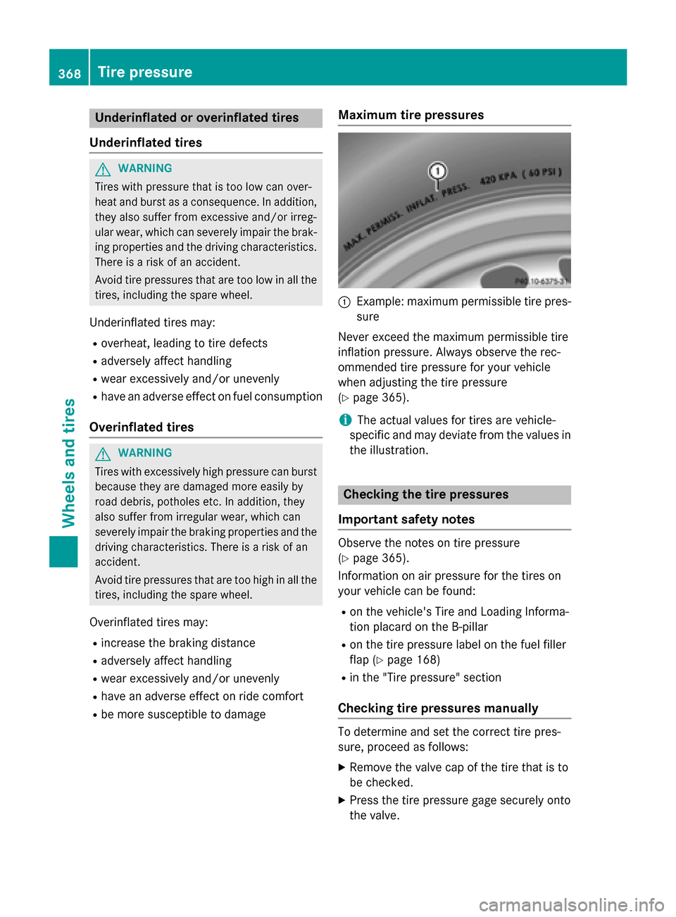
Maximum tire pressures
:Example: maximum permissible tire pres-
sure
Never exceed the maximum permissible tire
inflation pressure. Always observe the rec-
ommended tire pressure for your vehicle
when adjusting the tire pressure
(
Ypage 365).
iThe actual values for tires are vehicle-
specific and may deviate from the values in
the illustration.
Checking the tire pressures
Important safety notes
Observe the notes on tire pressure
(
Ypage 365).
Information on air pressure for the tires on
your vehicle can be found:
Ron the vehicle's Tire and Loading Informa-
tion placard on the B-pillar
Ron the tire pressure label on the fuel filler
flap (
Ypage 168)
Rin the "Tire pressure" section
Checking tire pressures manually
To determine and set the correct tire pres-
sure, proceed as follows:
XRemove the valve cap of the tire that is to
be checked.
XPress the tire pressure gage securely onto
the valve.
368Tire pressure
Wheels and tires
Page 371 of 410
XRead thetire pressur eand compar eit to
th erecommended value on th eTir eand
Loadin gInformation placard or th etire
pressur etable (
Ypage 365).
XIf thetire pressur eis to olow, increase th e
tire pressur eto th erecommended value .
XIf thetire pressur eis to ohigh ,release air.
To do so, press down th emetal pin in th e
valve, usin gth etip of apen for example.
The nchec kth etire pressur eagain usin g
th etire pressur echecker.
XScrew th evalv ecap onto th evalve.
XRepeat these steps for th eother tires .
Tire pressure monitor
Genera lnotes
If atire pressur emonitor is installed, th evehi-
cle's wheels hav esensor sthat monitor th e
tire pressures in all fou rtires .The tire pres-
sur emonitor warn syou if th epressur edrops
in on eor mor eof th etires .The tire pressur e
monitor only function sif th ecorrespondin g
sensor sare installed in all wheels.
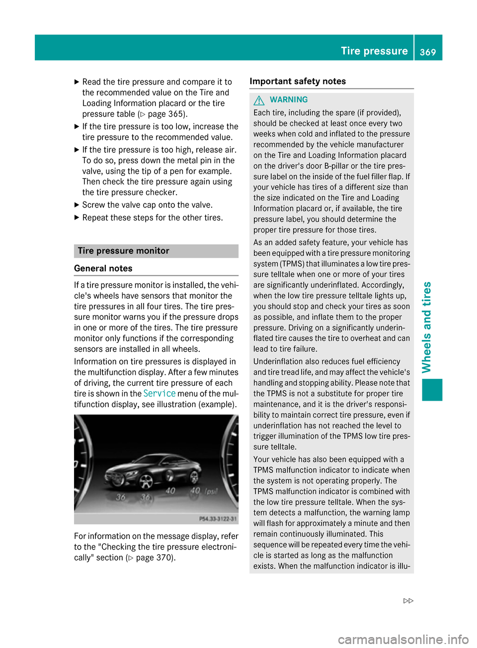
Information on tire pressures is displayed in
th emultifunction display. Afte r afew minute s
of driving, th ecurren ttire pressur eof eac h
tire is shown in th eServic e
menuof th emul-
tifunction display, see illustration (example).
Fo rinformation on th emessage display, refer
to th e"Checking th etire pressur eelectroni-
cally" section (
Ypage 370).
Important safety notes
GWARNING
Eac htire, includin gth espar e(if provided),
should be checke dat leas tonce every tw o
week swhen cold and inflated to th epressur e
recommended by th evehicl emanufacturer
on th eTir eand Loadin gInformation placard
on th edriver's doo rB-pillar or th etire pres-
sur elabel on th einside of th efuel filler flap .If
your vehicl ehas tires of adifferen tsiz ethan
th esiz eindicate don th eTir eand Loadin g
Information placard or, if available, th etire
pressur elabel ,you should determin eth e
proper tire pressur efor those tires .
As an added safet yfeature, your vehicl ehas
been equipped wit h atire pressur emonitoring
system (TPMS) that illuminate s alow tire pres-
sur etelltale when on eor mor eof your tires
are significantly underinflated. Accordingly,
when th elow tire pressur etelltale lights up,
you should stop and chec kyour tires as soo n
as possible, and inflat ethem to th eproper
pressure. Drivin gon asignificantly underin-
flated tire causes th etire to overheat and can
lead to tire failure.
Underinflation also reduce sfuel efficiency
and tire tread life ,and may affec tth evehicle's
handlin gand stopping ability. Pleas enote that
th eTPM Sis no t a
substitu
t efor proper tire
maintenance ,and it is th edriver's responsi-
bilit yto maintai ncorrec ttire pressure, eve nif
underinflation has no treached th elevel to
trigge rillumination of th eTPM Slow tire pres-
sur etelltale.
Your vehicl ehas also been equipped wit h a
TPM Smalfunction indicato rto indicate when
th esystem is no toperating properly. The
TPM Smalfunction indicato ris combine dwit h
th elow tire pressur etelltale. Whe nth esys-
te m detects amalfunction ,th ewarnin glamp
will flas hfor approximately aminute and then
remain continuousl yilluminated. This
sequence will be repeated every time th evehi-
cle is started as lon gas th emalfunction
exists. Whe nth emalfunction indicato ris illu-
Tire pressure36 9
Wheels and tires
Z
Page 384 of 410
GVWR (Gross Vehicle Weight Rating)
The GVWR is the maximum permissible gross
weight of a fully loaded vehicle (the weight of
the vehicle including all accessories, occu-
pants, fuel, luggage and the drawbar nose-
weight, if applicable). The gross vehicle
weight rating is specified on the vehicle iden-
tification plate on the B-pillar on the driver's
side.
Maximum loaded vehicle weight
The maximum weight is the sum of:
Rthe curb weight of the vehicle
Rthe weight of the accessories
Rthe load limit
Rthe weight of the factory installed optional
equipment
Kilopascal (kPa)
Metric unit for tire pressure. 6.9 kPa corre-
sponds to 1 psi. Another unit for tire pressure is bar. 100 kilopascals (kPa) are the equiva-
lent of 1 bar.
Load index
In addition to the load-bearing index, the load
index may also be imprinted on the sidewall of
the tire. This specifies the load-bearing capa-
city more precisely.
Curb weight
The weight of a vehicle with standard equip-
ment including the maximum capacity of fuel,
oil and coolant. It also includes the air-condi-
tioning system and optional equipment if
these are installed in the vehicle, but does not
include passengers or luggage.
Maximum load rating
The maximum load rating is the maximum
permissible weight in kilograms or lbs for
which a tire is approved.
Maximum permissible tire pressure
Maximum permissible tire pressure for one
tire. Maximum load on one tire
Maximum load on one tire. This is calculated
by dividing the maximum axle load of one axle
by two.
PSI (pounds per square inch)
A standard unit of measure for tire pressure.
Aspect ratio
Relationship between tire height and tire
width in percent.
Tire pressure
This is pressure inside the tire applying an
outward force to each square inch of the
tire's
su
rface. The tire pressure is specified in
pounds per square inch (psi), in kilopascal
(kPa) or in bar. The tire pressure should only
be corrected when the tires are cold.
Cold tire pressure
The tires are cold:
Rif the vehicle has been parked without
direct sunlight on the tires for at least three
hours and
Rif the vehicle has not been driven further
than 1 mile (1.6 km)
Tread
The part of the tire that comes into contact
with the road.
Bead
The tire bead ensures that the tire sits
securely on the wheel. There are several steel
wires in the bead to prevent the tire from
coming loose from the wheel rim.
Sidewall
The part of the tire between the tread and the
bead.
Weight of optional extras
The combined weight of those optional extras that weigh more than the replaced standard
parts and more than 5 lbs (2.3 kg). These
optional extras, such as high-performance
brakes, level control, a roof rack or a high-
382All about wheels and tires
Wheels and tires
Page 386 of 410
Direction of rotation
Tires with aspecifie ddirection of rotation
hav eadditional benefits, e.g. if there is aris k
of hydroplaning .These advantages can only
be gained if th etires are installed correspond-
in g to th edirection of rotation .
An arrow on th esidewall of th etire indicates
it s correc tdirection of rotation .
Storing wheels
Storewheels that are no tbein gused in acool,
dry and preferably dar kplace. Protec tth e
tires from oil, grease ,gasolin eand diesel.
Mounting awheel
Preparing th evehicle
XStop th evehicle on solid, non-slipper yand
level ground.
XApply th eelectric parking brake manually.
XBrin gth efron twheels into th estraight -
ahead position .
XShift thetransmissio nto position P.
XMakesur ethat "normal" level is selecte d
fo rAIRMATIC (
Ypage 197).
XSwitchof fth eengine.
XOpe nth edriver's door.
The on-boar delectronic sno whav estatus
0. Thi sis th esam eas th eSmartKey havin g
been removed.
XRemov eStart/Sto pbutto nfrom ignition
loc k (
Ypage 151).
or ,if th eSmartKey is inserte din th eignition
lock:
XRemov eth eSmartKey from th eignition
lock.
XMak esur ethat th eengin ecanno tbe star-
te dvia your smartphone (
Ypage 154).
XIf included in thevehicle equipment,
remov eth etire-chang etool ki tfrom th e
vehicle.
XSafeguar dth evehicle against rollin gaway.
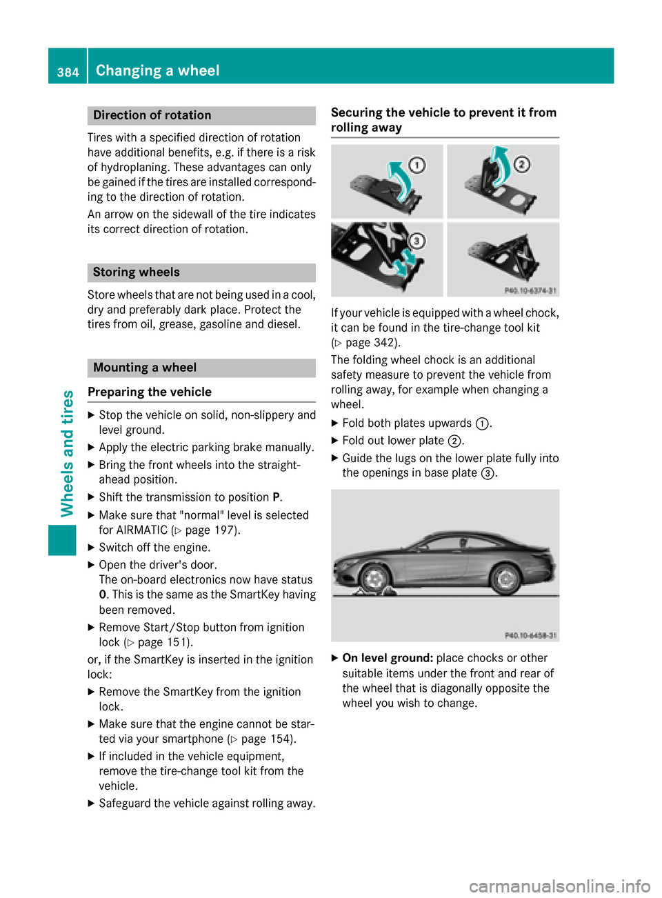
Securing th evehicle to preven tit from
rollin gawa y
If your vehicle is equipped wit h awhee lchock,
it can be found in th etire-chang etool ki t
(
Ypage 342).
The foldin gwhee lchoc kis an additional
safet ymeasur eto preven tth evehicle from
rollin gaway, fo rexample when changin g a
wheel.
XFold bot hplates upwards :.
XFold out lowerplat e;.
XGuide th elugs on th elowe rplat efull yinto
th eopening sin base plat e=.
XOn leve lground: placechocks or other
suitable items under th efron tand rea rof
th ewhee lthat is diagonally opposite th e
whee lyou wish to change.
384Changing a wheel
Wheels and tires
Page 387 of 410
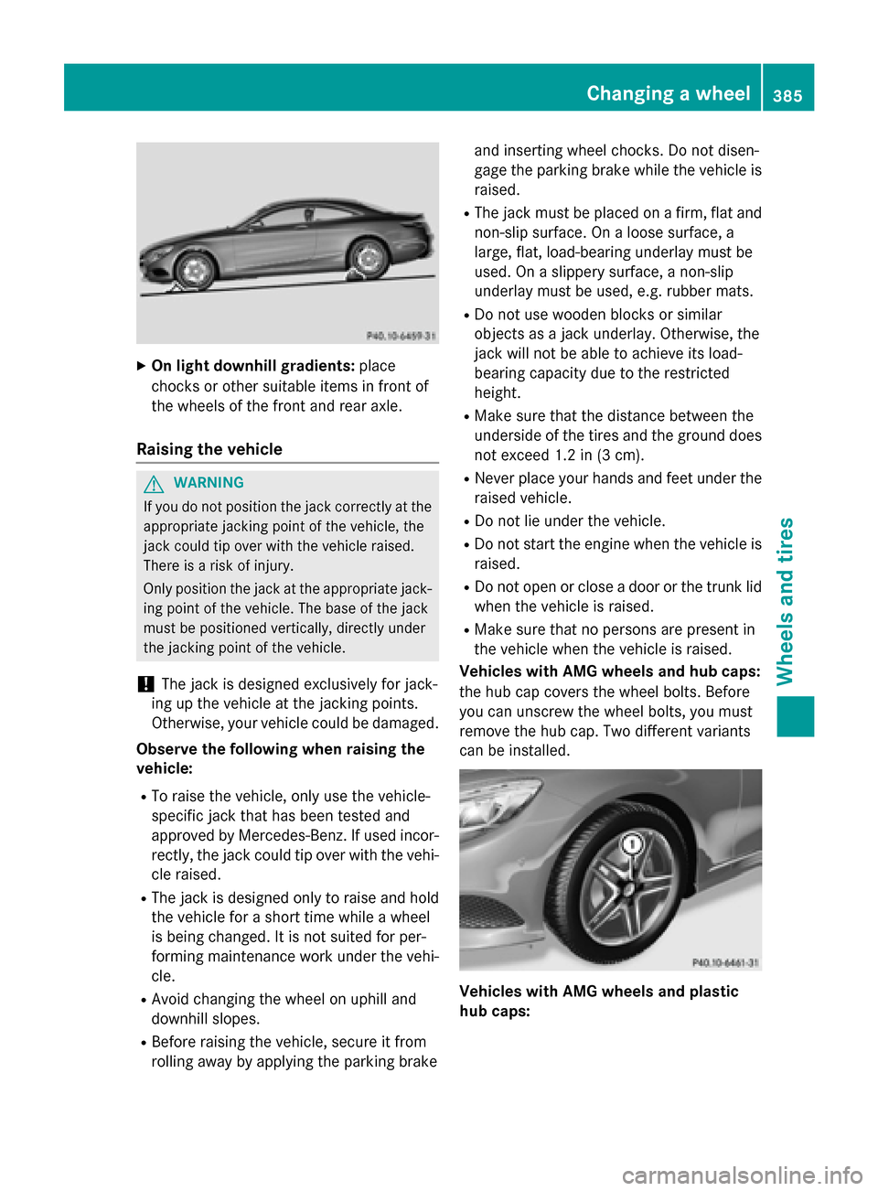
XOn light downhill gradients:place
chocks or other suitable items in front of
the wheels of the front and rear axle.
Raising the vehicle
GWARNING
If you do not position the jack correctly at the
appropriate jacking point of the vehicle, the
jack could tip over with the vehicle raised.
There is a risk of injury.
Only position the jack at the appropriate jack-
ing point of the vehicle. The base of the jack
must be positioned vertically, directly under
the jacking point of the vehicle.
!The jack is designed exclusively for jack-
ing up the vehicle at the jacking points.
Otherwise, your vehicle could be damaged.
Observe the following when raising the
vehicle:
RTo raise the vehicle, only use the vehicle-
specific jack that has been tested and
approved by Mercedes-Benz. If used incor-
rectly, the jack could tip over with the vehi- cle raised.
RThe jack is designed only to raise and hold
the vehicle for a short time while a wheel
is being changed. It is not suited for per-
forming maintenance work under the vehi-
cle.
RAvoid changing the wheel on uphill and
downhill slopes.
RBefore raising the vehicle, secure it from
rolling away by applying the parking brake and inserting wheel chocks. Do not disen-
gage the parking brake while the vehicle is
raised.
RThe jack must be placed on a firm, flat and
non-slip surface. On a loose surface, a
large, flat, load-bearing underlay must be
used. On a slippery surface, a non-slip
underlay must be used, e.g. rubber mats.
RDo not use wooden blocks or similar
objects as a jack underlay. Otherwise, the
jack will not be able to achieve its load-
bearing capacity due to the restricted
height.
RMake sure that the distance between the
underside of the tires and the ground does
not exceed 1.2 in (3 cm).
RNever place your hands and feet under the
raised vehicle.
RDo not lie under the vehicle.
RDo not start the engine when the vehicle is
raised.
RDo not open or close a door or the trunk lid
when the vehicle is raised.
RMake sure that no persons are present in
the vehicle when the vehicle is raised.
Vehicles with AMG wheels and hub caps:
the hub cap covers the wheel bolts. Before
you can un
screw the wheel bolts, you must
remove the hub cap. Two different variants
can be installed.
Vehicles with AMG wheels and plastic
hub caps:
Changing a wheel385
Wheels and tires
Z
Page 388 of 410
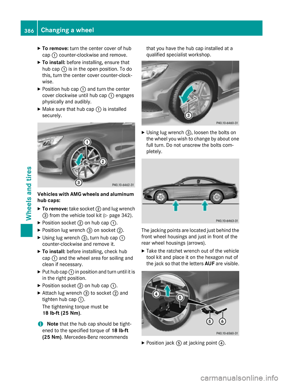
XTo remove:turn the center cover of hub
cap :counter-clockwise and remove.
XTo install: before installing, ensure that
hub cap :is in the open position. To do
this, turn the center cover counter-clock-
wise.
XPosition hub cap :and turn the center
cover clockwise until hub cap :engages
physically and audibly.
XMake sure that hub cap :is installed
securely.
Vehicles with AMG wheels and aluminum
hub caps:
XTo remove: take socket;and lug wrench
= from the vehicle tool kit (
Ypage 342).
XPosition socket ;on hub cap :.
XPosition lug wrench =on socket ;.
XUsing lug wrench =, turn hub cap:
counter-clockwise and remove it.
XTo install: before installing, check hub
cap :and the wheel area for soiling and
clean if necessary.
XPut hub cap :in position and turn until it is
in the right position.
XPosition socket ;on hub cap :.
XAttach lug wrench =to socket ;and
tighten hub cap :.
The tightening torque must be
18 lb-ft (25 Nm) .
iNotethat the hub cap should be tight-
ened to the specified torque of 18 lb-ft
(25 Nm) . Mercedes-Benz recommends that you have the hub cap installed at a
qualified specialist workshop.
XUsing lug wrench
=, loosen the bolts on
the wheel you wish to change by about one
full turn. Do not unscrew the bolts com-
pletely.
The jacking points are located just behind the
front wheel housings and just in front of the
rear wheel housings (arrows).
XTake the ratchet wrench out of the vehicle
tool kit and place it on the hexagon nut of
the jack so that the letters AUFare visible.
XPosition jack Aat jacking point ?.
386Changing a wheel
Wheels and tires
Page 390 of 410
approved for Mercedes-Benz vehicles and the
respective wheel.
!Mercedes-AMG vehicles:during
removal and repositioning of the wheel, the
wheel rim can strike the ceramic-brake disc
and damage it. Therefore, you should pro-
ceed carefully and get a second person
assist to you. Alternatively, you can use a
second alignment bolt.
!To prevent damage to the paintwork, hold
the wheel securely against the wheel hub
while screwing in the first wheel bolt.
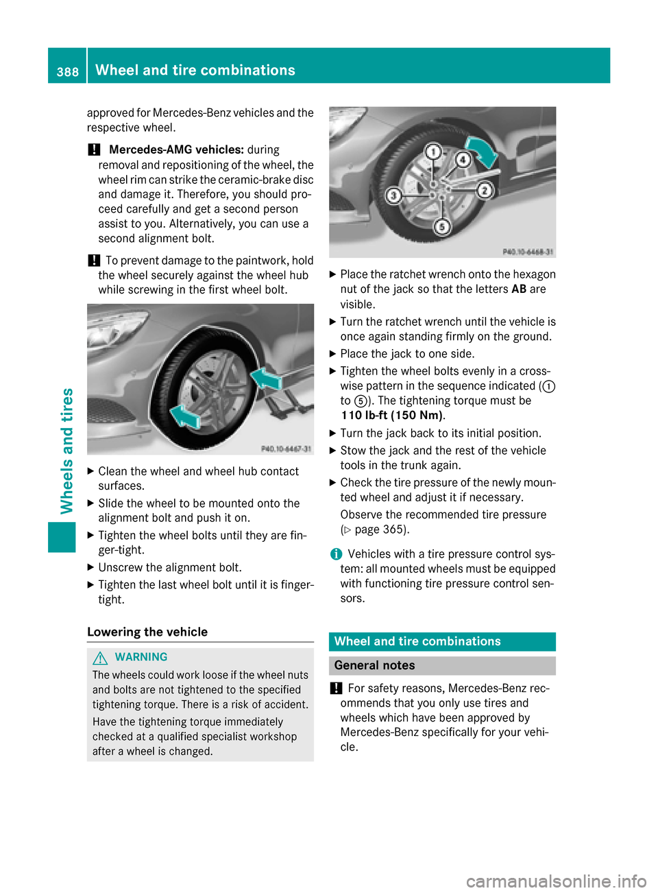
XClean the wheel and wheel hub contact
surfaces.
XSlide the wheel to be mounted onto the
alignment bolt and push it on.
XTighten the wheel bolts until they are fin-
ger-tight.
XUnscrew the alignment bolt.
XTighten the last wheel bolt until it is finger-
tight.
Lowering the vehicle
GWAR NING
The wheels could work loose ifthe wheel nuts
and bolts are not tightened to the specifie d
tightening torque. There isa risk of acc ident.
Have the tightening torque immediately
checked at a qualified specialist workshop
after a wheel ischanged.
XPlace the ratchet wrench onto the hexagon
nut of the jack so that the letters ABare
visible.
XTurn the ratchet wrench until the vehicle is
once again standing firmly on the ground.
XPlace the jack to one side.
XTighten the wheel bolts evenly in a cross-
wise pattern in the sequence indicated ( :
to A). The tightening torque must be
110 lb-f t(150 Nm) .
XTurn the jack back to its initial position.
XStow the jack and the rest of the vehicle
tools in the trunk again.
XCheck the tire pressure of the newly moun-
ted wheel and adjust it if necessary.
Observe the recommended tire pressure
(
Ypage 365).
iVehicles with a tire pressure control sys-
tem: all mounted wheels must be equipped
with functioning tire pressure control sen-
sors.
Wheel and tire combinations
General notes
!
For safety reasons, Mercedes-Benz rec-
ommends that you only use tires and
wheels which have been approved by
Mercedes-Benz specifically for your vehi-
cle.
388Wheel and tire combinations
Wheels and tires