mirror MERCEDES-BENZ S-Class MAYBACH 2017 W222 Service Manual
[x] Cancel search | Manufacturer: MERCEDES-BENZ, Model Year: 2017, Model line: S-Class MAYBACH, Model: MERCEDES-BENZ S-Class MAYBACH 2017 W222Pages: 382, PDF Size: 9.92 MB
Page 206 of 382
DrivingAssistance PLUS package
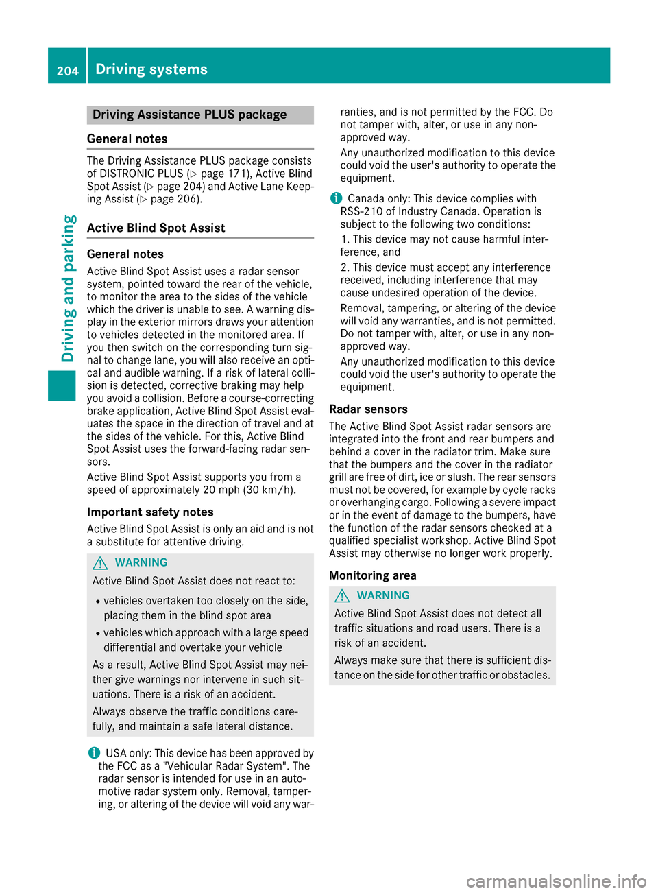
General notes
The Driving Assistanc ePLU Spackage consist s
of DISTRONIC PLU S (Ypage 171), Active Blin d
Spot Assis t (Ypage 204) and Active Lan eKeep-
in g Assis t (Ypage 206).
Active Blind Spot Assist
General notes
Active Blin dSpot Assis tuses aradar sensor
system, pointe dtoward th erea rof th evehicle,
to monito rth eare ato th esides of th evehicle
whic hth edriver is unable to see . Awarnin gdis -
play in th eexterio rmirrors draws your attention
to vehicles detecte din th emonitored area. If
you then switch on th ecorrespondin gturn sig -
nal to chang elane, you will also receiv ean opti-
cal and audible warning. If aris kof latera lcolli-
sio nis detected, corrective braking may hel p
you avoid acollision .Before acourse-correcting
brake application ,Active Blin dSpot Assis teval-
uates th espac ein th edirection of trave land at
th esides of th evehicle. Fo rthis, Active Blin d
Spot Assis tuses th eforward-facin gradar sen -
sors.
Active Blin dSpot Assis tsupports you from a
speed of approximately 20 mph (30 km/h).
Important safet ynotes
Active Blin dSpot Assis tis only an aid and is no t
a substitute fo rattentive driving.
GWARNING
Active Blin dSpot Assis tdoe sno treact to :
Rvehicles overtaken to oclosely on th eside,
placin gthem in th eblin dspo tare a
Rvehicles whic happroac hwit h a larg espeed
differential and overtak eyour vehicle
As aresult ,Active Blin dSpot Assis tmay nei-
ther giv ewarnings no rinterven ein suc hsit -
uations. There is aris kof an accident.
Always observ eth etraffic condition scare-
fully, and maintain asaf elatera ldistance.
iUS Aonly: Thi sdevic ehas bee napproved by
th eFCC as a"Vehicular Radar System". The
radar sensor is intended fo ruse in an auto-
motive radar syste monly. Removal, tamper-
ing, or altering of th edevic ewill void any war- ranties, and is no
tpermitte dby th eFCC. Do
no ttampe rwith, alter, or use in any non-
approved way.
An yunauthorized modification to this devic e
could void th euser's authorit yto operat eth e
equipment.
iCanada only: Thi sdevic ecomplies wit h
RSS-210 of Industry Canada. Operation is
subjec tto th efollowin gtw oconditions:
1. Thi sdevic emay no tcause harmful inter-
ference ,and
2. Thi sdevic emus taccept any i
nterferenc
e
received, includin ginterferenc ethat may
cause undesired operation of th edevice.
Removal, tampering, or altering of th edevic e
will void any warranties ,and is no tpermitted.
Do no ttampe rwith, alter, or use in any non-
approved way.
An yunauthorized modification to this devic e
could void th euser's authorit yto operat eth e
equipment.
Rada rsensor s
The Active Blind Spot Assis tradar sensor sare
integrated into th efron tand rea rbumper sand
behin d acover in th eradiator trim. Mak esur e
that th ebumper sand th ecover in th eradiator
grill are free of dirt, ic eor slush. The rea rsensor s
mus tno tbe covered, fo rexample by cycle racks
or overhangin gcargo. Followin g asevere impact
or in th eevent of damage to th ebumpers, hav e
th efunction of th eradar sensor schecke dat a
qualified specialis tworkshop .Active Blin dSpot
Assis tmay otherwise no longer wor kproperly.
Monitoring area
GWARNING
Active Blind Spot Assis tdoe sno tdetec tall
traffic situation sand road users. There is a
ris kof an accident.
Always mak esur ethat there is sufficien tdis -
tanc eon th esid efo rother traffic or obstacles.
204Driving systems
Driving an d parking
Page 208 of 382
signal remains on, detected vehicles are indica-
ted by the flashing of red warning lamp . There
are no further warning tones.
Course-correcting brake application
If Active Blind Spot Assist detects a risk of a lat-
eral collision in the monitoring range, a course-
correcting brake application is carried out. This
is meant to assist you in avoiding a collision.
GWARNING
A course-correcting brake application cannot always prevent a collision. There is a risk of an
accident.
Always steer, brake or accelerate yourself,
especially if Active Blind Spot Assist warns
you or makes a course-correcting brake appli-
cation. Always maintain a safe distance at the
sides.
If a course-correcting brake application occurs,
the red warning lamp flashes in the exterior mir-
ror and a dual warning tone sounds. In addition,
a display underlining the danger of a side colli-
sion appears in the multifunction display.
In very rare cases, the system may make an
inappropriate brake application. A course-cor-
recting brake application may be interrupted at
any time by countersteering slightly or acceler-
ating.
The course-correcting brake application is avail-
able in the speed range between 20 mph
(30 km/h) and 120 mph (200 km/h).
Either no braking application, or a course-cor-
recting brake application adapted to the driving situation occurs if:
Rthere are vehicles or obstacles, e.g. crash
barriers, located on both sides of your vehicle.
Ra vehicle approaches you too closely at the
side.
Ryou have adopted a sporty driving style with
high cornering speeds.
Ryou clearly brake or accelerate.
Ra driving safety system intervenes, e.g. ESP®
or PRE-SAFE®Brake.
RESP®is switched off.
Ra loss of tire pressure or a defective tire is
detected.
Switching on Active Blind Spot Assist
XMake sure that Active Blind Spot Assist is
activated in the on-board computer
(
Ypage 223)
XSwitch on the ignition.
Warning lamps in the exterior mirrors light up
red for approximately 1.5 seconds. Gray radarwaves propagating backwards appear next to
the vehicle in the assistance display on the
multifunction display.
Active Lane Keeping Assist
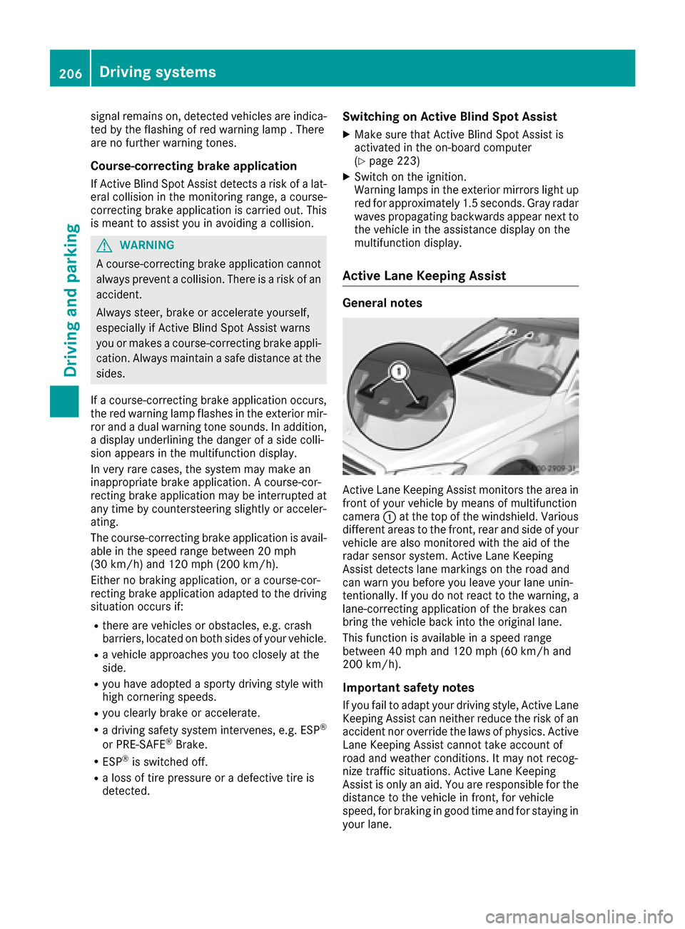
General notes
Active Lane Keeping Assist monitors the area in
front of your vehicle by means of multifunction
camera :at the top of the windshield. Various
different areas to the front, rear and side of your
vehicle are also monitored with the aid of the
radar sensor system. Active Lane Keeping
Assist detects lane markings on the road and
can warn you before you leave your lane unin-
tentionally. If you do not react to the warning, a
lane-correcting application of the brakes can
bring the vehicle back into the original lane.
This function is available in a speed range
between 40 mph and 120 mph (60 km/h and
200 km/h).
Important safety notes
If you fail to adapt your driving style, Active Lane
Keeping Assist can neither reduce the risk of an accident nor override the laws of physics. Active
Lane Keeping Assist cannot take account of
road and weather conditions. It may not recog-
nize traffic situations. Active Lane Keeping
Assist is only an aid. You are responsible for the
distance to the vehicle in front, for vehicle
speed, for braking in good time and for staying in
your lane.
206Driving systems
Driving and parking
Page 258 of 382
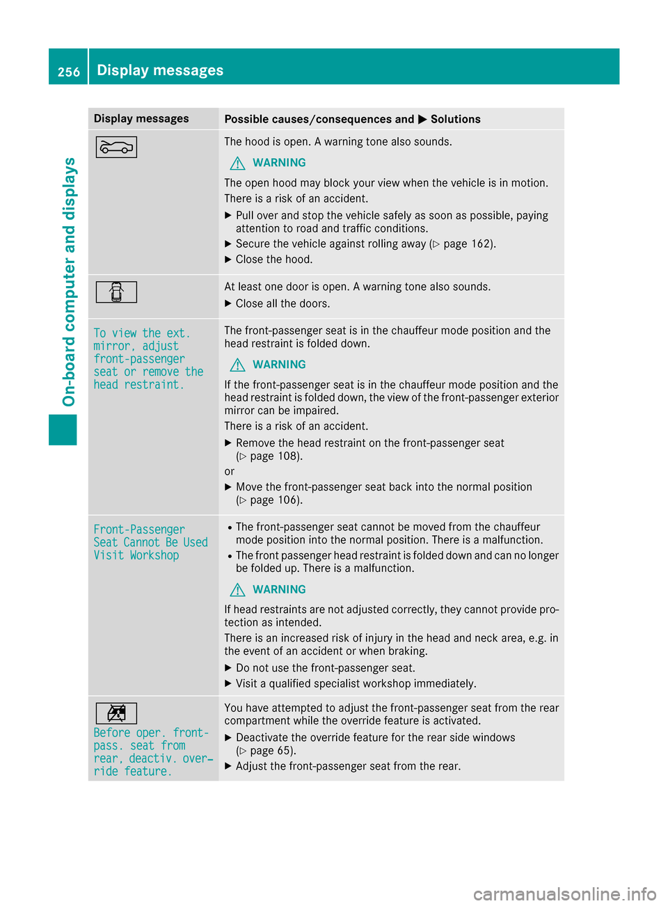
Display messagesPossible causes/consequences andMSolutions
MThe hoodis open . Awarning tone also sounds.
GWARNIN G
The open hoo dmay bloc kyour vie wwhen th evehicl eis in motion .
There is aris kof an accident.
XPull ove rand stop th evehicl esafely as soo nas possible, payin g
attention to roa dand traffic conditions.
XSecur eth evehicl eagainst rollin gaway (Ypage 162).
XCloseth ehood.
CAt least on edoor is open . Awarning tone also sounds.
XClos eall th edoors.
To vie wthe ext .mirror,adjustfront-passengersea tor remove thehea drestraint .
The front-passenger seat is in th echauffeur mod eposition and th e
head restrain tis folded down .
GWARNING
If th efront-passenger seat is in th echauffeur mod eposition and th e
head restrain tis folded down ,th evie wof th efront-passenger exterio r
mirror can be impaired.
There is aris kof an accident.
XRemove th ehead restrain ton th efront-passenger seat
(Ypage 108).
or
XMov eth efront-passenger seat bac kint oth enormal position
(Ypage 106).
Front-PassengerSea tCannotBeUsedVisit Workshop
RThe front-passenger seat canno tbe moved from th echauffeur
mod eposition int oth enormal position .There is amalfunction .
RThe frontpassenger head restrain tis folded down and can no longer
be folded up. There is amalfunction .
GWARNING
If head restraints are no tadjusted correctly, they canno tprovid epro -
tection as intended.
There is an increased ris kof injury in th ehead and neck area ,e.g. in
th eevent of an acciden tor when braking .
XDo notuse th efront-passenger seat .
XVisitaqualified specialist workshop immediately.
n
Before oper. front-pass. sea tfro mrear,deactiv.over‐ridefeature.
You hav eattempte dto adjust th efront-passenger seat from th erear
compartmen twhile th eoverride feature is activated.
XDeactivat eth eoverride feature for th erear side windows
(Ypage 65).
XAdjus tth efront-passenger seat from th erear .
256Display messages
On-board computer and displays
Page 294 of 382
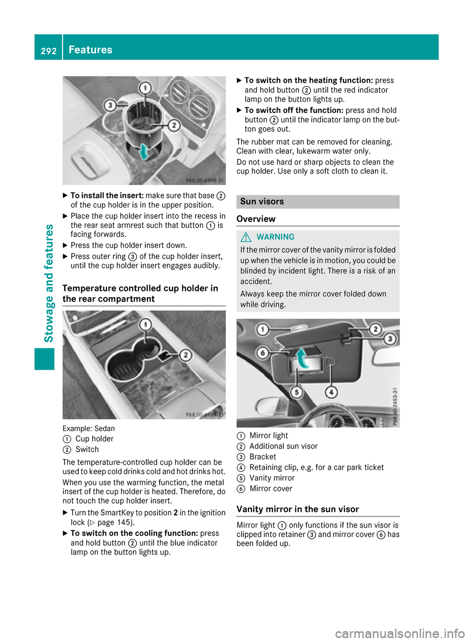
XTo install the insert:make sure that base;
of the cup holder is in the upper position.
XPlace the cup holder insert into the recess in
the rear seat armrest such that button :is
facing forwards.
XPress the cup holder insert down.
XPress outer ring =of the cup holder insert,
until the cup holder insert engages audibly.
Temperature controlled cup holder in
the rear compartment
Example: Sedan
:
Cup holder
;Switch
The temperature-controlled cup holder can be
used to keep cold drinks cold and hot drinks hot.
When you use the warming function, the metal
insert of the cup holder is heated. Therefore, do not touch the cup holder insert.
XTurn the SmartKey to position 2in the ignition
lock (Ypage 145).
XTo switch on the cooling function: press
and hold button ;until the blue indicator
lamp on the button lights up.
XTo switch on the heating function: press
and hold button ;until the red indicator
lamp on the button lights up.
XTo switch off the function: press and hold
button ;until the indicator lamp on the but-
ton goes out.
The rubber mat can be removed for cleaning.
Clean with clear, lukewarm water only.
Do not use hard or sharp objects to clean the
cup holder. Use only a soft cloth to clean it.
Sun visors
Overview
GWARNING
If the mirror cover of the vanity mirror is folded
up when the vehicle is in motion, you could be
blinded by incident light. There is a risk of an
accident.
Always keep the mirror cover folded down
while driving.
:Mirror light
;Additional sun visor
=Bracket
?Retaining clip, e.g. for a car park ticket
AVanity mirror
BMirror cover
Vanity mirror in the sun visor
Mirror light :only functions if the sun visor is
clipped into retainer =and mirror cover Bhas
been folded up.
292Features
Stowag ean d features
Page 309 of 382
Information on Roadside Assistance
(Ypage 28).
Downloading routes
Downloading routes allows you to transfer and
save predefined routes in the navigation sys-
tem.
A route can be prepared and sent by either a
customer service representative or under "Own-
ers Online" at http://www.mbusa.com.
Each route can include up to four way points.
Once a route has been received by the naviga-
tion system, you will see theDo
youwanttostart route guidance? DestinationReceived destination has been savedin "Previous destinations".message on
the multimedia system display.
The route is saved.
XTo start route guidance: selectYes.
An overview of the route is shown in the dis-
play.
If you select No
, the saved route can be called
up later in the navigation menu.
XSelect Start.
Route guidance starts.
Downloaded and saved routes can be called up
again.
Speed alert
You can define the upper speed limit, which
must not be exceeded by the vehicle.
If this selected speed is exceeded by the vehicle,
a message will be sent to the Customer Assis-
tance Center. The Customer Assistance Center
then forwards this information to you.
You can select the way in which you receive this
information beforehand. Possible options
include text message, e-mail or an automated
call.
The data you receive contains the following
information:
Rthe location where the speed limit was excee-
ded
Rthe time at which the speed limit was excee-
ded
Rthe selected speed limit which was exceeded
Geo fencing
Geo fencing allows you to select areas which the
vehicle should not enter or leave. You will be
informed if the vehicle crosses the boundaries
of the selected areas. You can select the way in
which you receive this information beforehand.
Possible options include text message, e-mail or an automated call.
The area can be determined as either a circle or
a polygon with a maximum of ten corners. You
can specify up to ten areas simultaneously. Dif-
ferent settings are possible for each area.
These settings can be called up under "Owners
Online" at http://www.mbusa.com.
Alternatively, you can trigger an Info call and
notify the customer service representative that
you wish to activate geo-fencing.
Currently inactive areas can be activated by text
message.
Triggering the vehicle alarm
With this function, you can trigger the vehicle's
panic alarm via text message. An alarm sounds
and the exterior lighting flashes. Depending on
the setting, the panic alarm lasts five or ten sec-onds. Afterwards, the alarm switches off.
Garage door opener
General notes
The HomeLink®garage door opener integrated
in the rear-view mirror allows you to operate up
to three different door and gate systems.
Use the integrated garage door opener only on
garage doors that:
Rhave safety stop and reverse features and
Rmeet current U.S. federal safety standards
Once programed, the integrated garage door
opener in the rear-view mirror will assume the
function of the garage door system's remote
control. Please also read the operating instruc-
tions for the garage door system.
When programming a garage door opener, park
the vehicle outside the garage. Do not run the
engine while programming.
Certain garage door drives are incompatible
with the integrated garage door opener. If you
have difficulty programing the integrated garage
Features307
Stowage and features
Z
Page 310 of 382
door opener, contact an authorized Mercedes-
Benz Center.
Alternatively, you can call the following tele-
phone assistance services:
RUSA:Mercedes-Benz Customer Assistance
Center at 1-800-FOR-MERCedes
RCanada: Customer Service at
1-800-387-0100
RHomeLink®hotline 1-800-355-3515 (free of
charge)
More information on HomeLink
®and/or com-
patible products is also available online at
http://www.homelink.co m.
Notes on the declaration of conformity
(
Ypage 29).
USA: FCC ID: CB2HMIHL4
Canada: IC: 279B-HMIHL4
Important safety notes
GWARNING
When you operate or program the garage door
with the integrated garage door opener, per-
sons in the range of movement of the garage
door can become trapped or struck by the
garage door. There is a risk of injury.
When using the integrated garage door
opener, always make sure that nobody is
within the range of movement of the garage
door.
GWARNING
Combustion engines emit poisonous exhaust
gases such as carbon monoxide. Inhaling
these exhaust gases leads to poisoning. There
is a risk of fatal injury. Therefore never leave
the engine running in enclosed spaces with-
out sufficient ventilation.
Programming
Programming buttons
Pay attention to the "Important safety notes"
(Ypage 308).
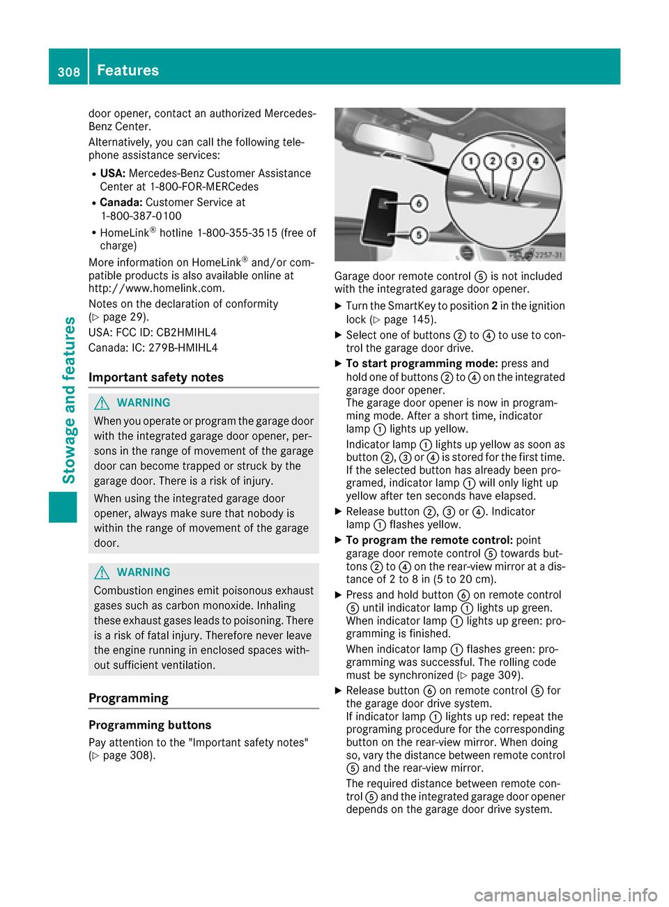
Garage door remote control Ais not included
with the integrated garage door opener.
XTurn the SmartKey to position 2in the ignition
lock (Ypage 145).
XSelect one of buttons ;to? to use to con-
trol the garage door drive.
XTo start programming mode: press and
hold one of buttons ;to? on the integrated
garage door opener.
The garage door opener is now in program-
ming mode. After a short time, indicator
lamp :lights up yellow.
Indicator lamp :lights up yellow as soon as
button ;,=or? is stored for the first time.
If the selected button has already been pro-
gramed, indicator lamp :will only light up
yellow after ten seconds have elapsed.
XRelease button ;,=or?. Indicator
lamp :flashes yellow.
XTo program the remote control: point
garage door remote control Atowards but-
tons ;to? on the rear-view mirror at a dis-
tance of 2 to 8 in (5 to 20 cm).
XPress and hold button Bon remote control
A until indicator lamp :lights up green.
When indicator lamp :lights up green: pro-
gramming is finished.
When indicator lamp :flashes green: pro-
gramming was successful. The rolling code
must be synchronized (
Ypage 309).
XRelease button Bon remote control Afor
the garage door drive system.
If indicator lamp :lights up red: repeat the
programing procedure for the corresponding
button on the rear-view mirror. When doing
so, vary the distance between remote control
A and the rear-view mirror.
The required distance between remote con-
trol Aand the integrated garage door opener
depends on the garage door drive system.
308Features
Stowage and features
Page 311 of 382
Several attempts might be necessary. You
should test every position for at least
25 seconds before trying another position.
Synchronizing the rolling code
Pay attention to the "Important safety notes"
(Ypage 308).
If the garage door system uses a rolling code,
you will also have to synchronize the garage
door system with the integrated garage door
opener in the rear-view mirror. To do this you will
need to use the programming button on the door
drive control panel. The programming button
may be located in different places depending on
the manufacturer. It is usually located on the
door drive unit on the garage ceiling.
Familiarize yourself with the garage door drive
operating instructions, e.g. under "Program-
ming additional remote controls", before carry-
ing out the following steps.
Your vehicle must be within reach of the garage
door or gate opener drive. Make sure that nei-
ther your vehicle nor any persons/objects are
present within the sweep of the door or gate.
XTurn the SmartKey to position 2in the ignition
lock (Ypage 145).
XGet out of the vehicle.
XPress the programming button on the door
drive unit.
Usually, you now have 30 seconds to initiate
the next step.
XGet into the vehicle.
XPress previously programed button ;,=
or ? on the integrated garage door opener
repeatedly and in quick succession until the
door closes.
The rolling code synchronization is then com- plete.
Notes on programming the remote con-
trol
Canadian radio frequency laws require a "break"(or interruption) of the transmission signals
after broadcasting for a few seconds. Therefore,
these signals may not last long enough for the
integrated garage door opener. The signal is not recognized during programming. Comparable
with Canadian law, some U.S. garage door open-
ers also feature a "break". Proceed as follows:
Rif you live in Canada
Rif you have difficulties programming the
garage door opener (regardless of where you
live) when using the programming steps
XPress and hold one of buttons
;to? on the
integrated garage door opener.
After a short time, indicator lamp :lights up
yellow.
XRelease the button.
Indicator lamp :flashes yellow.
XPress button Bof garage door remote con-
trol Afor two seconds, then release it for two
seconds.
XPress and hold button Bon remote control
A again for two seconds.
XRepeat this sequence on button Bof remote
control Auntil indicator lamp :lights up
green.
When indicator lamp :lig
hts up green: pro-
gramming is finished.
When indicator lamp :flashes green: pro-
gramming was successful. The next step is to
synchronize the rolling code.
XRelease button Bof remote control Aof the
garage door drive.
If indicator lamp :lights up red: repeat the
programming process for the corresponding
button on the rear-view mirror. When doing
so, vary the distance between remote control
A and the rear-view mirror.
The required distance between remote con-
trol Aand the integrated garage door opener
depends on the garage door drive system.
Several attempts might be necessary. You
should test every position for at least
25 seconds before trying another position.
Problems when programming
If you are experiencing problems programing
the integrated garage door opener on the rear-
view mirror, take note of the following instruc-
tions:
RCheck the transmitter frequency used by
garage door drive remote control Aand
whether it is supported. The transmitter fre-
quency can usually be found on the back of
remote control Afor the garage door drive.
Features309
Stowage and features
Z
Page 312 of 382
The garage door opener is compatible with
devices which operate in the frequency range
of 280 to 433 MHz.
RReplace the batteries in garage door remote
controlA. This increases the likelihood that
garage door remote control Awill transmit a
strong and precise signal to the integrated
garage door opener.
RWhen programming, hold remote control A
at varying distances and angles from but-
tons ;to? which you are programming. Try
various angles at a distance between 2and
8 inches (5to 20 cm) or at the same angle but
at varying distances.
RIf another remote control Ais available for
the same garage door drive, repeat the same
programming steps with this remote control
A. Before performing these steps, make sure
that new batteries have been installed in
garage door drive remote control A.
RNote that some remote controls only transmit
for a limited amount of time (the indicator
lamp on the remote control goes out). Press
buttonBon remote control Aagain before
transmission ends.
RAlign the antenna cable of the garage door
opener unit. This can improve signal recep-
tion/transmission.
Opening/closing the garage door
After it has been programmed, the integrated
garage door opener performs the function of the
garage door system remote control. Please also
read the operating instructions for the garage
door system.
XTurn the SmartKey to position 2in the ignition
lock (Ypage 145).
XPress button ;,=or? which you have
programmed to operate the garage door.
Garage door system with a fixed code: indi-
cator lamp :lights up green.
Garage door system with a rolling code: indi-
cator lamp :flashes green.
The transmitter will transmit a signal as long
as the button is pressed. The transmission is
halted after a maximum of ten seconds and
indicator lamp :lights up yellow.
XPress button ;,=or? again if necessary.
Clearing the memory
Make sure that you clear the memory of the
integrated garage door opener before selling the
vehicle.
XTurn the SmartKey to position 2in the ignition
lock (Ypage 145).
XPress and hold buttons ;and ?.
The indicator lamp initially lights up yellow
and then green.
XRelease buttons ;and ?.
The memory of the integrated garage door
opener in the rear-view mirror is cleared.
Floormats
GWARNING
Objects in the driver's footwell can restrict the pedal travel or obstruct a depressed pedal.
The operating and road safety of the vehicle is
jeopardized. There is a risk of an accident.
Make sure that all objects in the vehicle are
stowed correctly, and that they cannot enter
the driver's footwell. Install the floormats
securely and as specified in order to ensure
sufficient clearance for the pedals. Do not use
loose floormats and do not place floormats on
top of one another.
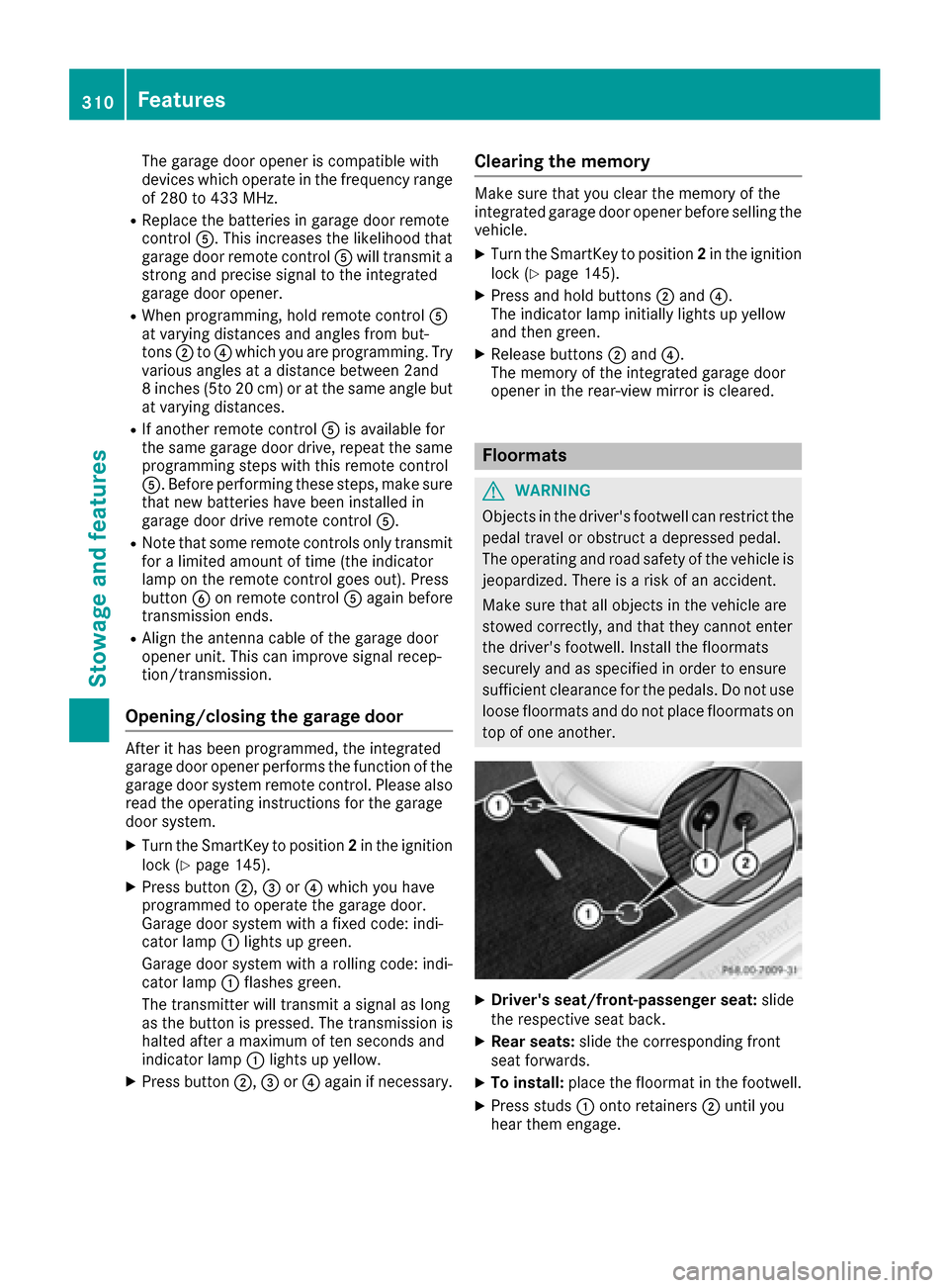
XDriver's seat/front-passenger seat: slide
the respective seat back.
XRear seats: slide the corresponding front
seat forwards.
XTo install: place the floormat in the footwell.
XPress studs :onto retainers ;until you
hear them engage.
310Features
Stowage and features
Page 325 of 382
Cleaning the mirror turn signals
!Only use cleaning agents or cleaning cloths
that are suitable for plastic lenses. Unsuitable
cleaning agents or cleaning cloths could
scratch or damage the plastic lenses of the
mirror turn signals.
XClean the plastic lenses of the mirror turn sig-
nals in the exterior mirror housing using a wet
sponge and mild cleaning agent, e.g.
Mercedes-Benz car shampoo or cleaning
cloths.
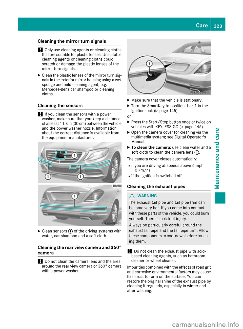
Cleaning the sensors
!If you clean the sensors with a power
washer, make sure that you keep a distance
of at least 11.8 in (30 cm)betwee nthe vehicl e
and the power washer nozzle. Information
about the correct distance is available from
the equipment manufacturer.
XClean sensors :of the driving systems with
water, car shampoo and a soft cloth.
Cleaning the rear view camera and 360°
camera
!Do not clean the camera lens and the area
around the rear view camera or 360° camera
with a power washer.
XMake sure that the vehicle is stationary.
XTurn the SmartKey to position 1or 2in the
ignition lock (Ypage 145).
or
XPress the Start/Stop button once or twice on
vehicles with KEYLESS-GO (Ypage 145).
XOpen the camera cover for cleaning via the
multimedia system; see Digital Operator's
Manual.
XTo clean the camera: use clean water and a
soft cloth to clean the camera lens :.
The camera cover closes automatically:
Rif you are driving at speeds above 6 mph
(10 km/ h)
Rif the ignition is switched off
Cleaning the exhaust pipes
GWARNING
The exhaust tail pipe and tail pipe trim can
become very hot. If you come into contact
with these parts of the vehicle, you could burn
yourself. There is a risk of injury.
Always be particularly careful around the
exhaust tail pipe and the tail pipe trim. Allow
these components to cool down before touch-
ing them.
!Do not clean the exhaust pipe with acid-
based cleaning agents, such as bathroom
cleaner or wheel cleaner.
Impurities combined with the effects of road grit and corrosive environmental factors may cause
flash rust to form on the surface. You can
restore the original shine of the exhaust pipe by
cleaning it regularly, especially in winter and
after washing.
Care323
Maintenance and care
Z
Page 379 of 382
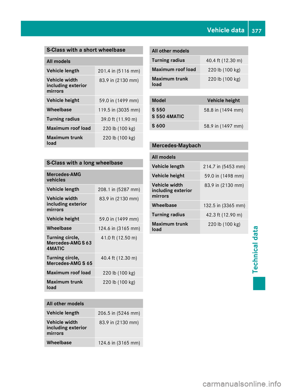
S-Class with a short wheelbase
All models
Vehicle length201.4 in (5116 mm)
Vehicle width
including exterior
mirrors83.9 in (2130 mm)
Vehicle height59.0 in (1499 mm)
Wheelbase119.5 in (3035 mm)
Turning radius39.0 ft (11.90m)
Maximum roof load220 lb (100 kg)
Maximum trunk
load220 lb (100 kg)
S-Class with a long wheelbase
Mercedes‑AMG
vehicles
Vehicle length208.1 in (5287 mm)
Vehicle width
including exterior
mirrors83.9 in (2130 mm)
Vehicle height59.0 in (1499 mm)
Wheelbase124.6 in (3165 mm)
Turning circle,
Mercedes-AMG S 63
4MATIC41.0 ft (12.50m)
Turning circle,
Mercedes‑AMG S 6540.4 ft (12.30 m)
Maximum roof load220 lb (100 kg)
Maximum trunk
load220 lb (100 kg)
All other models
Vehicle length206.5 in (5246 mm)
Vehicle width
including exterior
mirrors83.9 in (2130 mm)
Wheelbase124.6 in (3165 mm)
All other models
Turning radius40.4 ft (12.30m)
Maximum roof load220 lb (100 kg)
Maximum trunk
load220 lb (100 kg)
ModelVehicle height
S 550
S 550 4MATIC58.8 in (1494 mm)
S 60058.9 in (1497 mm)
Mercedes‑Maybach
All models
Vehicle length214.7 in (5453 mm)
Vehicle height59.0 in (1498 mm)
Vehicle width
including exterior
mirrors83.9 in (2130 mm)
Wheelbase132.5 in (3365 mm)
Turning radius42.3 ft (12.90m)
Maximum trunk
load220 lb (100 kg)
Vehicle data377
Technical data
Z