battery MERCEDES-BENZ S-CLASS SALOON LONG 2020 Owners Manual
[x] Cancel search | Manufacturer: MERCEDES-BENZ, Model Year: 2020, Model line: S-CLASS SALOON LONG, Model: MERCEDES-BENZ S-CLASS SALOON LONG 2020Pages: 609, PDF Size: 10.5 MB
Page 6 of 609
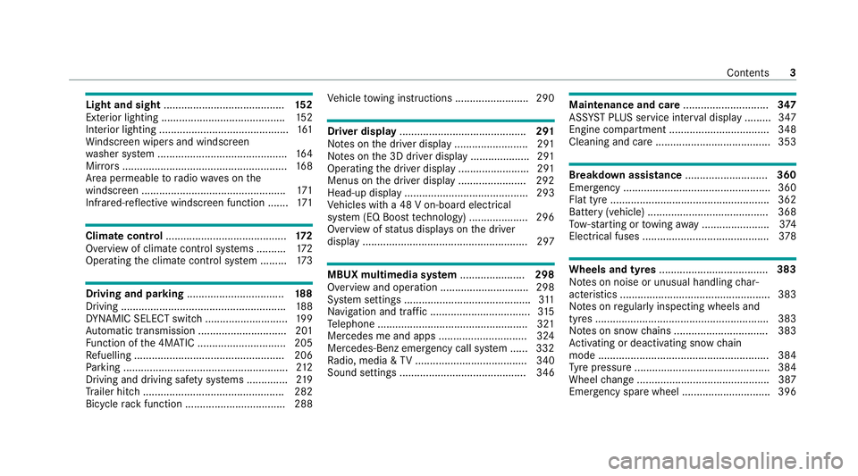
Light and sight
......................................... 15 2
Exterior lighting .......................................... 15 2
Interior lighting ............................................ 161
Wi ndsc reen wipers and windscreen
wa sher sy stem ............................................ 16 4
Mir rors ........................................................ 16 8
Area pe rmeable toradio wav es on the
windscreen ................................................ .171
Infrared-reflective windscreen function ....... 171Climate control
......................................... 17 2
Overview of climate contro l systems ..........1 72
Operating the climate control sy stem ......... 173 Driving and pa
rking ................................. 18 8
Driving ........................................................ 188
DY NA MIC SELECT switch ............................1 99
Au tomatic transmission .............................. 201
Fu nction of the 4MATIC .............................. 205
Re fuelling ................................................... 206
Pa rking ........................................................ 212
Driving and driving sa fety sy stems .............. 219
Tr ailer hit ch................................................ 282
Bicycle rack function .................................. 288 Ve
hicle towing instructions ........................ .290 Driver display
........................................... 291
No tes on the driver display .........................2 91
No tes on the 3D driver display .................... 291
Operating the driver display ........................ 291
Menus on the driver display ....................... 292
Head-up display .......................................... 293
Ve hicles with a 48 V on-board electrical
sy stem (EQ Boost tech nology) .................... 296
Overview of status displa yson the driver
display ........................................................ 297 MBUX multimedia sy
stem ...................... 298
Overview and operation .............................. 298
Sy stem settings ...........................................3 11
Na vigation and traf fic .................................. 315
Te lephone .................................................. .321
Mercedes me and apps .............................. 324
Mercedes-Benz emer gency call sy stem ...... 332
Ra dio, media & TV...................................... 340
Sound settings ........................................... 346 Main
tenance and care ............................. 347
ASS YST PLUS service inter val display ........ .347
Engine compartment .................................. 348
Cleaning and care ....................................... 353 Breakdown assistance
............................360
Emergency ................................................. .360
Flat tyre ...................................................... 362
Battery (vehicle) ......................................... 368
To w- starting or towing away ....................... 374
Electrical fuses ........................................... 378 Wheels and tyres
..................................... 383
No tes on noise or unusual handling char‐
acteristics .................................................. .383
No tes on regular lyinspecting wheels and
tyres .......................................................... .383
No tes on snow chains ................................ 383
Ac tivating or deacti vating snow chain
mode .......................................................... 384
Ty re pressure .............................................. 384
Wheel change ............................................ .387
Emergency spare wheel .............................. 396 Contents
3
Page 36 of 609
&
WARNING Risk of accident due tocon‐
necting devices tothe diagnostics con‐
nection
If yo u connect devices tothe diagnostics
connection of theve hicle, the function of
ve hicle sy stems and operating saf ety may be
impaired. #
For saf etyre asons, werecommend that
yo u on lyuse and connect products
appr ovedby yo ur Mercedes-Benz
service centre. &
WARNING Risk of accident due to
objects in the driver's foot we ll
Objects in the driver's foot we ll may impede
pedal tr avel or block a depressed pedal.
This jeopardises the operating and road
saf ety of theve hicle. #
Stow all objects in theve hicle securely
so that they cannot getinto the driver's
fo ot we ll. #
Alw aysfit th efloor mats securely and
as prescribed in order toensure that th
ere is alw ays suf ficient room forthe
pedals. #
Do not use loose floor mats and do not
place floor mats on top of one ano ther. *
NO
TEBattery discharging from using
devices connected tothe diagnostics
connection Using devices at
the diagnostics connection
drains the batter y. #
Check thech arge leve l of the batter y. #
Ifth ech arge leve l is lo w,charge the
batter y,e.g. bydriving a considerable
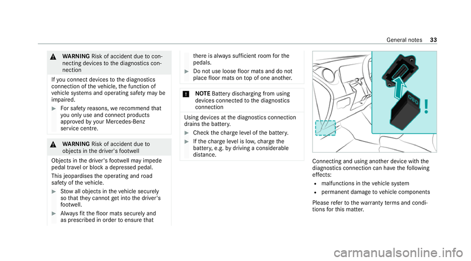
dis tance. Connecting and using ano
ther device with the
diagnostics connection can ha vethefo llowing
ef fects:
R malfunctions in theve hicle sy stem
R permanent damage tovehicle components
Please referto thewa rranty term s and condi‐
tions forth is matter. General no
tes33
Page 40 of 609
tion, number of wheel
revo lutions or thefa s‐
te ned seat belts displ ay
R ambient conditions, such as temp erature,
ra in sensor or dis tance sensor
General ly,th e use of these data is temp orar y;
th ey will not be stored be yond the period of
operation and will only be processed within the
ve hicle itself. Control units of ten contain da ta
memories forve hicle keys,fo rex ample. Their
use permits thete mp orary or permanent docu‐
mentation of tech nical information about the
ve hicle's operating state, component loads,
main tenance requ irements and tech nical events
or faults.
Depending on theve hicle equipment, thefo llow‐
ing data are stored:
R operating status of sy stem components,
such as fill le vels, tyre pressure or battery
st atus
R malfunctions or faults in impor tant sy stem
components, such as lights or brakes
R system reactions in special driving situations,
such as airbag deployment or the inter ven‐
tion of stability control sy stems R
information on events leading tovehicle
damage
In cer tain cases, it may be requiredtostore data
th at wo uld ha veotherwise been used only tem‐
poraril y.This may be the case if theve hicle has
de tected a malfunction, forex ample.
If yo u use services, such as repair services and
maintenance work,st ored operational data as
we ll as theve hicle identification number can be
re ad out and used. They can be read out by
service network emplo yees, such as workshops
and manufacturers or third parties, such as
breakdown services. The same is true in the
case of warranty claims and quality assurance
measures.
In general, there adout is per form ed via the
legally prescribed port forth e diagnostics con‐
nection in theve hicle. The operational data that
are read out document tech nical states of the
ve hicle or of individual components and assist in
th e diagnosis of malfunctions, compliance with
wa rranty obligations and quality impr ovement.
To that end, these data, in particular information
about component loads, tech nical events, mal‐ functions and
other faults may be transmitted
along with theve hicle identification number to
th e manufacturer. Furthermore, the manufac‐
turer is subject toproduct liability. Forth is rea‐
son the manufacturer also uses operational data
from theve hicle, forex ample, forre calls. These
da ta can also be used toexamine the cus tom‐
er's warranty and guarantee claims.
Fa ult memories in theve hicle can be reset by a
service outlet or at your requ est as part of repair
or maintenance work.
Con venience and inf otainment functions
Yo u can store con venience settings and individ‐
ual settings in theve hicle and change or reset
th em at any time.
Depending on theve hicle equipment, this
includes thefo llowing settings, forex ample:
R seat and steering wheel positions
R suspension and climate control settings
R individual settings, such as interior lighting
Depending on the selected equipment, you can
import data into vehicle inf otainment functions
yo urself. General no
tes37
Page 80 of 609
Key
Overview of
key functions &
WARNING Risk of accident and inju ry
due toleaving children unat tended in the
ve hicle
If ch ildren are left unat tended in theve hicle,
th ey could, in pa rticular:
R open doors, thereby endangering other
persons or road users.
R get out and be stru ck byoncoming traf‐
fi c.
R ope rate ve hicle equipment and become
trapped, forex ample.
In addition, thech ildren could also set the
ve hicle in motion by,fo rex ample:
R releasing the parking brake.
R changing the transmission position.
R starting theve hicle. #
Never lea vechildren unat tended in the
ve hicle. #
When leaving theve hicle, alw aysta ke
th eke y with you and lock theve hicle. #
Keep theve hicle key out of there ach of
ch ildren. *
NO
TEDama getotheke y caused by
magnetic fields #
Keep theke yaw ay from strong mag‐
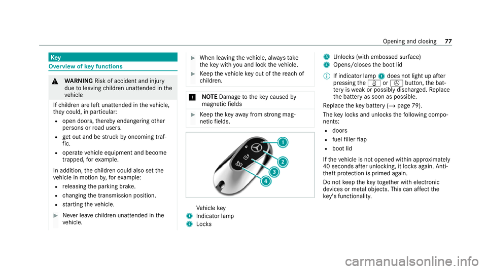
netic fields. Ve
hicle key
1 Indicator lamp
2 Locks 3
Unloc ks(with embossed sur face)
4 Opens/closes the boot lid
% If indicator lamp 1does not light up af ter
pressing theÜ ors button, the bat‐
te ry iswe ak or possibly dischar ged. Re place
th e battery as soon as possible.
Re place theke y bat tery ( / page 79).
The key loc ksand unlo cksth efo llowing compo‐
nents:
R doors
R fuel filler flap
R boot lid
If th eve hicle is not opened within appr oximately
40 seconds af ter unlocking, it loc ksagain. Anti-
th eft pr otection is primed again.
Do not keep theke yto get her with electronic
devices or me tal objects. This can af fect the
ke y's functionalit y. Opening and closing
77
Page 82 of 609
possible with
that particular key.Activate the
function of theke y so that all its functions will
again be available.
Yo u can also deactivate the function of thekey
to reduce the energy consum ption of theke y if
yo u do not use theve hicle or a keyfo r an exten‐
ded pe riod of time. #
Todeactivate: pressthes button on the
ke y twice in quick succession.
The key indicator lamp flashes twice brief ly
and lights up once. #
Toactivate: press any button on thekey.
% When theve hicle is star ted with theke y in
th estow age compartment of the cent recon‐
sole, the function of theke y is automatical ly
activated (/ page189). Re
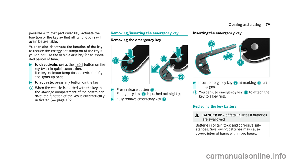
moving/inserting the eme rgency key Re
moving the eme rgency key #
Press release button 1.
Emer gency key2 is pushed out slight ly. #
Fully remo veemer gency key2. Inserting
the emer gency key #
Insert emergency key2 at marking 3until
it en gage s.
% You can use eme rgency key2 toattach the
ke yto ake yring. Re
placing the key battery &
DANG ER Risk of fata l injuries if batteries
are swallo wed
Batteries contain toxic and cor rosive sub‐
st ances. Swallowing bat teries may cause
se vere internal burns within two hours. Opening and closing
79
Page 83 of 609
There is a
risk of fata l injur y. #
Keep batteries out of there ach of chil‐
dren. #
Ifth e co ver and/or lid of the battery
compartment does not close securel y,
do not use theke y and keep it away
from children. #
If batteries are swallo wed, seek medical
attention immediately. +
ENVIRONMEN
TALNO TEEnvironmental
dama gedue toimproper disposal of bat‐
te ries Batteries conta
in pollutants. It is
illegal todispose of them with the household
ru bbish. #
Dispose of batteries in an
environmen tally responsible manner.
Ta ke dischar ged batteries toaqu alified
specialist workshop or toa collection
point for used batteries. Re
quirements:
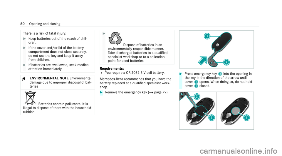
R Yourequ ire a CR 2032 3 V cell batter y.
Mercedes-Benz recommends that you ha vethe
battery replaced at a qualified specialist work‐
shop. #
Remo vethe emer gency key ( / page 79). #
Press eme rgency key2 into the opening in
th eke y in the direction of the ar row until
co ver1 opens. When doing so, do not hold
co ver1 closed. 80
Opening and closing
Page 84 of 609
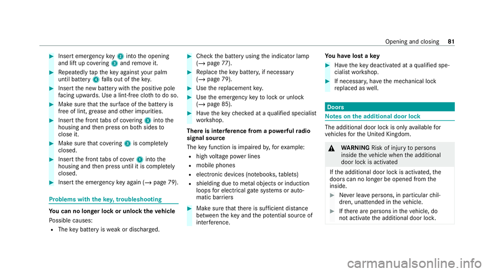
#
Insert emergency key2 into the opening
and lift up co vering 3 and remo veit. #
Repeatedly taptheke y again styour palm
until bat tery 4 falls out of thekey. #
Insert the new battery with the positive pole
fa cing up wards. Use a lint-free clo thtodo so. #
Make sure that the sur face of the battery is
free of lint, grease and other impurities. #
Insert the front tabs of co vering 3 into the
housing and then press on bo thsides to
close it. #
Makesure that co vering 3 is compl etely
closed. #
Insert the front tabs of co ver1 into the
housing and then press until it is comple tely
closed. #
Insert the emer gency key again ( /page 79). Problems with
theke y,troublesho oting Yo
u can no lon ger lo ckor unlock theve hicle
Po ssible causes:
R The key bat tery iswe ak or dischar ged. #
Check the battery using the indicator lamp
(/ page 77). #
Replace theke y bat tery, if necessary
(/ page 79). #
Use there placement key. #
Use the emer gency keyto lock or unlock
(/ page 85). #
Have theke ych ecked at a qualified specialist
wo rkshop.
There is inter fere nce from a po werful radio
signal source
The key function is impaired by,fo rex ample:
R high voltage po wer lines
R mobile phones
R electronic devices (no tebooks, tablets)
R shielding due tome tal objects or induction
loops for electrical gatesystems or auto‐
matic bar riers #
Make sure that there is suf ficient di stance
between theke y and the po tential sou rce of
inter fere nce. Yo
u ha velost a key #
Have theke y deacti vated at a qualified spe‐
cialist workshop. #
If necessar y,ha ve the mechanical lock
re placed as well. Doors
Note
s onthe additional door lock The additional door lock is only
available for
ve hicles forth eUni ted Kingdom. &
WARNING Risk of inju ryto persons
inside theve hicle when the additional
door lock is activated
If th e additional door lock is activated, the
doors can no longer be opened from the
inside. #
Never lea vepersons, in particular chil‐
dren, unat tended in theve hicle. #
Ifth ere are persons in theve hicle, do
not activate the additional door loc k. Opening and closing
81
Page 87 of 609
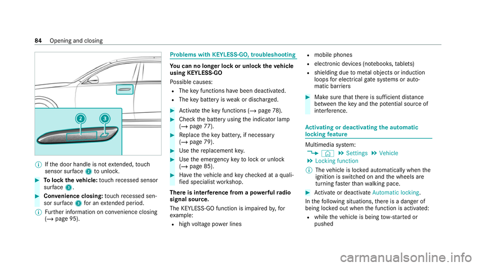
%
Ifth e door handle is not extended, touch
sensor sur face 2 tounlo ck. #
Tolock theve hicle: touch recessed sensor
su rface 3. #
Con venience closing: touch recessed sen‐
sor su rface 3for an extended pe riod.
% Further information on con venience closing
(/ page 95). Problems with
KEYLESS-GO, troubleshooting Yo
u can no lon ger lo ckor unlock theve hicle
using KEYLESS-GO
Po ssible causes:
R The key functions ha vebeen deactivated.
R The key bat tery iswe ak or dischar ged. #
Activate theke y functions (/ page78). #
Check the battery using the indicator lamp
(/ page 77). #
Replace theke y bat tery, if necessary
(/ page 79). #
Use there placement key. #
Use the emer gency keyto lock or unlock
(/ page 85). #
Have theve hicle and keych ecked at a quali‐
fi ed specialist workshop.
There is inter fere nce from a po werful radio
signal source.
The KEYLESS-GO function is impaired by,for
ex ample:
R high voltage po wer lines R
mobile phones
R electronic devices (no tebooks, tablets)
R shielding due tome tal objects or induction
loops for electrical gate systems or auto‐
matic bar riers #
Make sure that there is suf ficient di stance
between theke y and the po tential sou rce of
inter fere nce. Ac
tivating or deactivating the automatic
lo ck ing feature Multimedia sy
stem:
4 © 5
Settings 5
Vehicle
5 Locking function
% The vehicle is loc ked automatically when the
ignition is switched on and the wheels are
turning faster than walking pace. #
Activate or deacti vate Automatic locking .
In thefo llowing situations, there is a danger of
being loc ked out when the function is activated:
R while theve hicle is being tow- star ted or
pushed 84
Opening and closing
Page 100 of 609
#
Check the battery using the indicator lamp
(/ page 77). #
Replace theke y bat tery, if necessary
(/ page 79). Sliding sunroof
Opening and closing
the sliding sunroof %
The term "sliding sun roof" refers to the pan‐
orama sliding sunroof. &
WARNING Risk of becoming trapped
when the sliding sunroof is being opened
and closed
Body parts may become trapped in thera nge
of mo vement. #
During the opening and closing proc‐
ess, make sure that no body parts are
in the sweep of the sliding sunroof. #
If someone is trapped, release the con‐
trol panel immediatel y.
or #
Touch the control panel during auto‐
matic operation.
The opening/closing process will be
st opped. &
WARNING Risk of entrapment if the slid‐
ing sunroof is operated bychildren
Children operating the sliding sunroof could
get caught in the moving parts, particularly if
unattended. #
Never lea vechildren unat tended in the
ve hicle. #
When leaving theve hicle, alw aysta ke
th eke y with you and lock theve hicle. &
WARNING Risk of becoming trapped
when thero ller sunblind is being opened
and closed
Body parts may become trapped between
th ero ller sunblind and frame or sliding roof. #
During the opening or closing process,
make sure that no body parts are in the
ro ller sunblind's range of mo vement. #
If someone is trapped, release the con‐
trol panel immediatel y.
or #
Touch the control panel during auto‐
matic operation.
The opening/closing process will be
st opped. *
NO
TEMalfunction due tosnow and ice Snow and ice may cause
the sliding sunroof
to malfunction. #
Open the sliding sunroof only if it is free
of snow and ice. *
NO
TEDama gecaused byprotru ding
objects Objects
that pr otru de from the sliding sun‐
ro of may damage the sealing strips. Opening and closing
97
Page 148 of 609
#
Insert the plug of the device into 230 V
soc ket2.
When the on-board electrical sy stem voltage
is suf ficient, indicator la mp1lights up. USB port in
there ar passenger comp artmentDepending on
theve hicle equipment, theve hicle
has thefo llowing USB ports in there ar
passenger compartment:
R Inthe electronics compartment in the cent re
console of there ar passenger compartment .
R Inthestow age compartment in there ar arm‐
re st .
% These USB ports in there ar passenger com‐
partment can be used tocharge a mobile
end device.
Yo u can charge a USB device, such as a mobile
phone, at the USB ports using a suitable charg‐
ing cable. Depending on theve hicle equipment,
th e devices can be charge d with up to20 V (5 A)
when the ignition is switched on. Coolbox
Using
there frigerator box &
WARNING Risk offire due toa co vered
ve ntilation grille on the coolbox
If yo u co verth eve ntilation grille forth e cool‐
box, it may overheat. #
Alw ays make sure that theve ntilation
grille is not co vered. The
vent grille forth ere frigerator box is in the
boot.
The refrigerator box can bear a maximum load of
3.5 kg.
The upper compartment of there frigerator box
can accommodate, forex ample, plastic bottles
with a maximum capacity of 0.5 lit res and cans
with a capacity of up to0.33 litres
If yo u do not need touse there frigerator box for
an extended pe riod, you should swit chit off,
defrost it and clean it. Af ter doing so, lea vethe
lid open for a time. The
refrigerator box will reduce its cooling capa‐
city or switch off in thefo llowing cases:
R Too many electrical consumers are turned
on.
R The star ter battery is not suf ficiently
ch arge d.
If th is is the case, the indicator lamps will flash
on the button for switching there frigerator box
on and off. The cooling function will auto mati‐
cally switch back on as soon as there is suf fi‐
cient voltage. Seats and
stowing 14 5