battery MERCEDES-BENZ S430 2000 W220 Owner's Guide
[x] Cancel search | Manufacturer: MERCEDES-BENZ, Model Year: 2000, Model line: S430, Model: MERCEDES-BENZ S430 2000 W220Pages: 421, PDF Size: 20.52 MB
Page 254 of 421
251 Driving instructions
Te ch n ica l
data Instruments
and controlsOperationDrivingInstrument
cluster displayPractical hints Car care Index Winter driving
Have your vehicle winterized at your authorized
Mercedes-Benz Center before the onset of winter.
•Change the engine oil if the engine contains an oil
which is not approved for winter operation. For
viscosity (SAE / CCMC class) and filling quantity,
see page 396.
•Check engine coolant anticorrosion / antifreeze
concentration.
•Additive for the windshield washer and headlamp
cleaning system: Add MB Concentrate “S” to a
premixed windshield washer solvent / antifreeze
which is formulated for below freezing
temperatures, see page 337.
•Test battery: Battery capacity drops with decreasing
ambient temperature. A well charged battery helps
to ensure that the engine can be started, even at low
ambient temperatures.•Tires: We recommend M+S rated radial-ply tires on
all four wheels for the winter season. Observe
permissible maximum speed for M+S rated
radial-ply tires and the legal speed limit.
Note:
In winter operation, the maximum effectiveness of the
ABS and ESP can only be achieved with M+S rated
radial-ply tires and / or snow chains recommended by
Mercedes-Benz. Snow chains maximize performance.
Block heater (for Canada only)
The engine is equipped with a block heater.
The electrical cable may be installed at your authorized
Mercedes-Benz Center.
Page 278 of 421
275 Driving systems
Te ch n ica l
data Instruments
and controlsOperationDrivingInstrument
cluster displayPractical hints Car care Index Notes:
The yellow ESP warning lampv in the speedometer
dial comes on with the electronic key in starter switch
position 2. It should go out with the engine running.
If the ESP warning message is displayed, a malfunction
has been detected in the system. Only partial engine
output will be available.
Have the ESP checked at your authorized
Mercedes-Benz Center as soon as possible.
For ESP warning message, see page 301.
With the ABS malfunctioning, the ESP is also switched
off.
Driving the vehicle with varied size tires will cause the
wheels to rotate at different speeds, therefore the ESP
may activate (yellow ESP warning lamp in speedometer
dial comes on). For this reason, all wheels, including the
spare wheel, must have the same tire size. When testing the parking brake on a brake test
dynamometer, the engine must be shut off. Otherwise,
the ESP will immediately be engaged and will apply the
rear wheel brakes.
In winter operation, the maximum effectiveness of the
ESP is only achieved with Mercedes-Benz recommended
M+S rated radial-ply tires and / or snow chains.
Synchronizing ESP
If the power supply was interrupted (battery
disconnected or empty), the ESP warning message may
be displayed with the engine running.
Turn steering wheel completely to the left and then to
the right. The ESP warning message should go out.
Page 298 of 421
295 Contents - Instrument cluster display
Te ch n ica l
data Instruments
and controlsOperation DrivingInstrument
cluster displayPractical hints Car care Index
Instrument cluster displayMalfunction and indicator
lamps in the
instrument cluster ....................296
On-board diagnostic system .....296
Check engine malfunction
indicator lamp .............................296
Brake warning lamp ..................298
Supplemental restraint
system (SRS)
indicator lamp .............................299
Fuel reserve warning .................299
ABS malfunction
indicator lamp .............................300
Electronic stability
program (ESP) —
warning lamp ..............................301
Distronic (DTR) –
warning lamp ..............................301
Seat belt nonusage
warning lamp ..............................302Malfunction and
indicator lamp in the
center console ........................... 302
AIRBAG OFF indicator lamp .... 302
Malfunction and
warning messages in the
multifunction display .............. 303
DISPLAY DEFECTIVE ................ 304
BATTERY/ALTERNATOR .......... 305
ENTRANCE POSITION .............. 306
BRAKE ASSIST ........................... 306
BRAKE LINING WEAR .............. 307
BRAKE FLUID ............................ 307
PARKING BRAKE ....................... 308
TRUNK OPEN ............................. 308
ELEC. STABIL. PROG.
(Electronic stability
program) ..................................... 309
COOLANT (coolant level) .......... 310
COOLANT
(coolant temperature) ................ 311LIGHTING SYSTEM .................... 312
LIGHT SENSOR ........................... 314
ACTIV E BO DY CO NTROL
(ABC) ............................................ 314
TIRE PRESSURE ......................... 316
ENGINE OIL LEVEL ................... 318
CRUISE CONTROL ..................... 319
KEY ............................................... 319
DOOR ...........................................320
HOOD ...........................................320
TELE AID .....................................321
OIL TEMP.
(engine oil temperature) ...........321
CHIP-CARD (KEYLESS-GO) ......322
SELECTOR LEVER ......................323
TELEPHONE – FUNCTION .......323
WASHER FLUID .........................324
AIR SPRING (AirMatic) .............325
DISTRONIC (DTR) ......................326
Page 308 of 421
305 Malfunction and warning messages
Te ch n ica l
data Instruments
and controlsOperation DrivingInstrument
cluster displayPractical hints Car care Index BATTERY / ALTERNATOR
* C = Category, see page 303
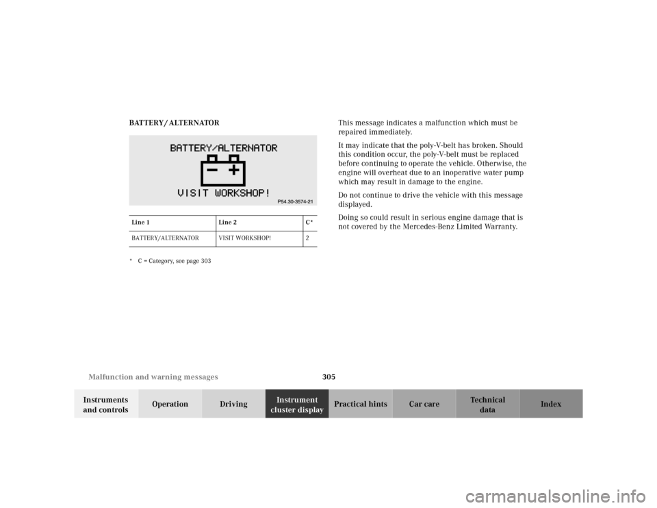
This message indicates a malfunction which must be
repaired immediately.
It may indicate that the poly-V-belt has broken. Should
this condition occur, the poly-V-belt must be replaced
before continuing to operate the vehicle. Otherwise, the
engine will overheat due to an inoperative water pump
which may result in damage to the engine.
Do not continue to drive the vehicle with this message
displayed.
Doing so could result in serious engine damage that is
not covered by the Mercedes-Benz Limited Warranty.
Line 1Line 2C*
BATTERY/ALTERNATOR VISIT WORKSHOP! 2
Page 312 of 421
309 Malfunction and warning messages
Te ch n ica l
data Instruments
and controlsOperation DrivingInstrument
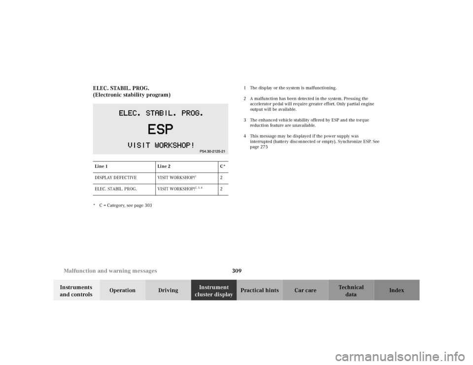
cluster displayPractical hints Car care Index ELEC. STABIL. PROG.
(Electronic stability program)
* C = Category, see page 3031 The display or the system is malfunctioning.
2 A malfunction has been detected in the system. Pressing the
accelerator pedal will require greater effort. Only partial engine
output will be available.
3 The enhanced vehicle stability offered by ESP and the torque
reduction feature are unavailable.
4 This message may be displayed if the power supply was
interrupted (battery disconnected or empty). Synchronize ESP. See
page 275
Line 1Line 2C*
DISPLAY DEFECTIVE VISIT WORKSHOP!
1
2
ELEC. STABIL. PROG. VISIT WORKSHOP!
2, 3, 4
2
Page 325 of 421
322 Malfunction and warning messages
Te ch n ica l
data Instruments
and controlsOperation DrivingInstrument
cluster displayPractical hints Car care Index
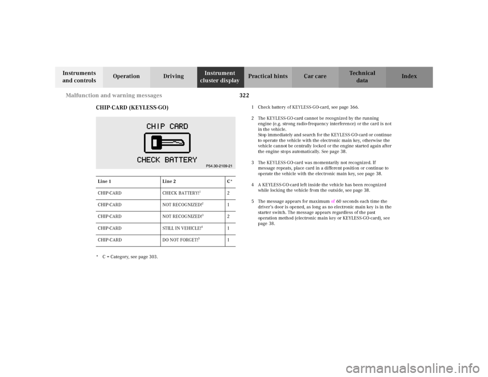
CHIP-CARD (KEYLESS-GO)
* C = Category, see page 303.1 Check battery of KEYLESS-GO-card, see page 366.
2 The KEYLESS-GO-card cannot be recognized by the running
engine (e.g. strong radio-frequency interference) or the card is not
in the vehicle.
Stop immediately and search for the KEYLESS-GO-card or continue
to operate the vehicle with the electronic main key, otherwise the
vehicle cannot be centrally locked or the engine started again after
the engine stops automatically. See page 38.
3 The KEYLESS-GO-card was momentarily not recognized. If
message repeats, place card in a different position or continue to
operate the vehicle with the electronic main key, see page 38.
4 A KEYLESS-GO-card left inside the vehicle has been recognized
while locking the vehicle from the outside, see page 38.
5 The message appears for maximum of 60 seconds each time the
driver’s door is opened, as long as no electronic main key is in the
starter switch. The message appears regardless of the past
operation method (electronic main key or KEYLESS-GO-card), see
page 38. Line 1Line 2C*
CHIP-CARD CHECK BATTERY!
1
2
CHIP-CARD NOT RECOGNIZED!
2
1
CHIP-CARD NOT RECOGNIZED!
3
2
CHIP-CARD STILL IN VEHICLE!
4
1
CHIP-CARD DO NOT FORGET!
5
1
Page 330 of 421
327 Contents - Practical hints
Te ch n ica l
data Instruments
and controlsOperation DrivingInstrument
cluster displayPractical hintsCar care Index
Practical hintsFirst aid kit .....................................328
Stowing things in the vehicle ......328
Fuses ................................................329
Hood ................................................. 331
Checking engine oil level .............334
Automatic transmission
fluid level ...................................335
Active body control
(ABC) fluid level ........................335
Coolant level ...................................336
Adding coolant ...........................336
Windshield and
headlamp washer system ........337Windshield and
headlamp washer fluid
mixing ratio ................................ 337
Spare wheel, vehicle tools,
storage compartment ............... 338
Vehicle jack .................................... 339
Wheels ............................................ 340
Tire Replacement ....................... 340
Rotating wheels ......................... 341
Spare wheel .................................... 341
Changing wheels ........................... 343
Tire inflation pressure ................. 348
Battery ............................................. 349
Jump starting ................................. 351
Towing the vehicle ........................ 353Exterior lamps ................................356
Headlamp assembly ...................357
Taillamp assemblies ..................360
Trunk lamp .....................................362
Changing batteries in the
electronic main key ..................363
Synchronizing
remote control ............................365
Changing batteries in the
KEYLESS-GO-card .....................366
Emergency engine
shut-down ..................................368
Fuel filler flap,
manual release ..........................368
Emergency operation of
sliding/pop-up roof ...................369
Replacing wiper blades .................370
Roof rack ......................................... 371
Page 352 of 421
349 Battery
Te ch n ica l
data Instruments
and controlsOperation DrivingInstrument
cluster displayPractical hintsCar care Index The spare tire should be checked periodically for
condition and inflation. Spare tire will age and become
worn over time even if never used, and thus should be
inspected and replaced when necessary.Battery
Important!
Battery replacement information:
The maintenance-free battery is located in the trunk
under the right-hand wheel well cover panel.
The service life of the battery is dependent on its
condition of charge. The battery should always be kept
sufficiently charged, in order to last an optimum length
of time.
Wa r n i n g !
Do not overinflate tires. Overinflating tires can
result in sudden deflation (blowout) because they
are more likely to become punctured or damaged
by road debris, potholes etc.. Follow recommended
inflation pressures.Do not overload the tires by exceeding the specified
vehicle capacity weight (as indicated by the label
on the driver’s door latch post). Overloading the
tires can overheat them, possibly causing a
blowout.
Wa r n i n g !
Failure to follow these instructions can result in
severe injury or death.Never lean over batteries while connecting, you
might get injured.Battery fluid contains sulfuric acid. Do not allow
this fluid to come in contact with eyes, skin or
clothing. In case it does, immediately flush affected
area with water and seek medical help if necessary.A battery will also produce hydrogen gas, which is
flammable and explosive. Keep flames or sparks
away from battery, avoid improper connection of
jumper cables, smoking etc..
Page 353 of 421
350 Battery
Te ch n ica l
data Instruments
and controlsOperation DrivingInstrument
cluster displayPractical hintsCar care Index
Therefore, we strongly recommend that you have the
battery charge checked frequently, and corrected if
necessary, especially if you use the vehicle less than
approximately 200 miles (300 km) per month,
mostly for short distance trips, or if it is not used for
long periods of time.
Only charge a battery with a battery charger after the
battery has been disconnected from the vehicle’s
electrical circuit.
Always disconnect the battery negative lead first and
connect last.
When removing and connecting the battery, always
make sure that all electrical consumers are off and the
electronic key is in starter switch position 0. The
battery, its filler caps, the vent tube and the opposite
plu g must always b e securely installed w hen the veh icle
is in operation.
While the engine is running the battery terminal clamps
must not be loosened or detached, otherwise the
generator and other electronic components would be
damaged.Note:
After reconnecting the battery also set the clock (see
COMAND operator’s manual) resynchronize the front
seat head restraints, the express feature of the power
windows, the sliding / pop-up roof, and the electronic
stability program (see head restraints on page 72, power
windows on page 181, and electronic stability program
on page 274).
Battery recycling
Batteries contain materials that can harm the
environment with improper disposal.
Large 12 Volt storage batteries contain lead.
Recycling of batteries is the preferred method of
disposal.
Many states require sellers of batteries to accept old
batteries for recycling.
Page 354 of 421
351 Jump starting
Te ch n ica l
data Instruments
and controlsOperation DrivingInstrument
cluster displayPractical hintsCar care Index Jump startingImportant!
A discharged battery can freeze at approximately +14°F
(–10°C). In that case, it must be thawed out before
jumper cables are used. Attempting to jump start a
frozen battery can result in it exploding, causing
personal injury.
Jumper cable specifications:
•Minimum cable cross-section of 25 mm
2 or
approximately 2 AWG
•Maximum length of 11.5 ft. (3.5 m).
If the battery is discharged, the engine should be started
with jumper cables and the (12 V) battery of another
vehicle.
Only use 12 V battery to jump start your vehicle. Jump
starting with more powerful battery could damage the
vehicle’s electrical systems, which will not be covered
by the Mercedes-Benz Limited Warranty.
The battery is located in the trunk under the right-hand
wheel well cover panel.
Wa r n i n g !
Failure to follow these directions will cause
damage to the electronic components, and can lead
to a battery explosion and severe injury or death.Never lean over batteries while connecting or jump
starting, you might get injured.Battery fluid contains sulfuric acid. Do not allow
this fluid to come in contact with eyes, skin or
clothing. In case it does, immediately flush affected
area with water, and seek medical help if
necessary.A battery will also produce hydrogen gas, which is
flammable and very explosive. Keep flames or
sparks away from battery, avoid improper
connection of jumper cables, smoking etc..Read all instructions before proceeding.