MERCEDES-BENZ S430 2002 W220 Owner's Manual
Manufacturer: MERCEDES-BENZ, Model Year: 2002, Model line: S430, Model: MERCEDES-BENZ S430 2002 W220Pages: 430, PDF Size: 20.81 MB
Page 111 of 430
108 Memory function
Te ch n i c a l
data Instruments
and controlsOperationDrivingInstrument
cluster displayPractical hints Car care Index
Memory function
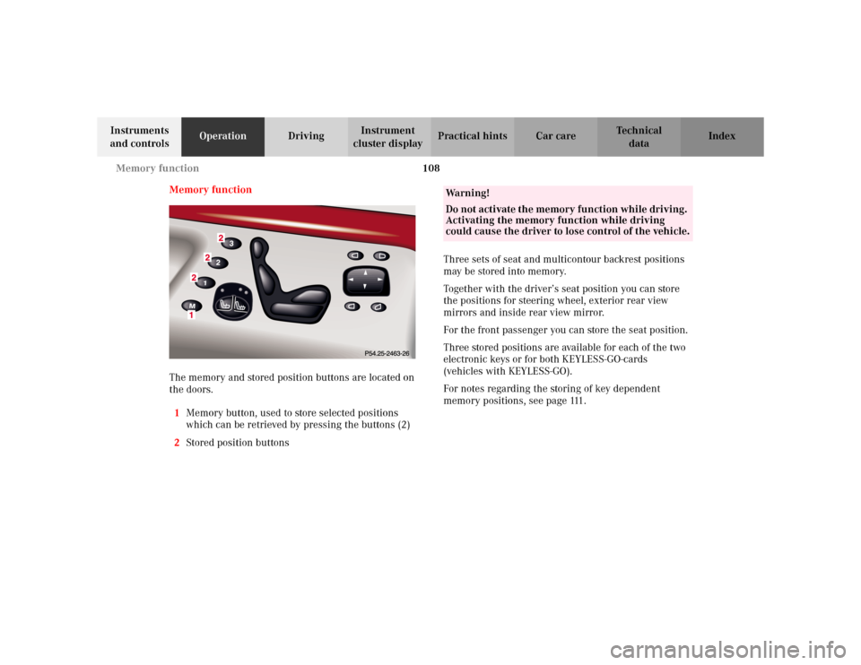
The memory and stored position buttons are located on
the doors.
1Memory button, used to store selected positions
which can be retrieved by pressing the buttons (2)
2Stored position buttonsThree sets of seat and multicontour backrest positions
may be stored into memory.
Together with the driver’s seat position you can store
the positions for steering wheel, exterior rear view
mirrors and inside rear view mirror.
For the front passenger you can store the seat position.
Three stored positions are available for each of the two
electronic keys or for both KEYLESS-GO-cards
(vehicles with KEYLESS-GO).
For notes regarding the storing of key dependent
memory positions, see page 111.
Wa r n i n g !
Do not activate the memory function while driving.
Activating the memory function while driving
could cause the driver to lose control of the vehicle.
Page 112 of 430
109 Memory function
Te ch n i c a l
data Instruments
and controlsOperationDrivingInstrument
cluster displayPractical hints Car care Index Storing positions into memory
Driver’s seat: with the electronic key in starter switch
position 1 or 2 or with the driver’s door open.
Front passenger seat and rear seats: with electronic key
in starter switch position 1 or 2 or the relevant doors
open.
Adjust the seat and multicontour backrest to the desired
position. You can also adjust the steering wheel, the
exterior rear view mirrors electrically and the inside
rear view mirror by hand for the driver’s seat. See
page 104 for exterior rear view mirror adjustment and
page 102 for steering wheel adjustment.
Push memory button “M”, release and push a stored
position button “1”, “2” or “3” within 3 seconds.Recalling positions from memory
To recall a seat / steering wheel and rear view mirror
position, push and hold button “1”, “2” or “3” until seat /
steering wheel and rear view mirror movement has
stopped.
The seat / steering wheel and rear view mirror
movement stops when the button is released.
Caution!
Do not operate the power seats using the memory
button if the seat backrest is in an excessively reclined
position. Doing so could cause damage to front or rear
seats.
First move backrest to an upright position.
Page 113 of 430
110 Memory function
Te ch n i c a l
data Instruments
and controlsOperationDrivingInstrument
cluster displayPractical hints Car care Index
Important!
Prior to operating the vehicle, the driver should check
and adjust if necessary the seat height, seat position
fore and aft, and backrest angle to insure adequate
control, reach and comfort. The head restraint should
also be adjusted for proper height. See also airbag
section for proper seat positioning.
In addition, also adjust the steering wheel to ensure
adequate control, reach, operation and comfort. Both the
inside and outside rear view mirrors should be adjusted
for adequate rearward vision.
Fasten seat belts. Infants and small children should be
seated in a properly secured restraint system that
complies with U.S. Federal Motor Vehicle Safety
Standard 213 and Canadian Motor Vehicle Safety
Standard 213.
All seat, head restraint, steering wheel, and rear view
mirror adjustments as well as fastening of seat belts
should be done before the vehicle is put into motion.
Wa r n i n g !
Children 12 years old and under must never ride in
the front seat, except in a Mercedes-Benz
authorized BabySmart
TM compatible child seat,
which operates with the BabySmart
TM system
installed in the vehicle to deactivate the passenger-
side front airbag when it is properly installed.
Otherwise they will be struck by the airbag when it
inflates in a crash. If this happens, serious or fatal
injury can result.
According to accident statistics, children are safer
when properly restrained in the rear seating
positions than in the front seating positions.
Infants and small children must ride in back seats
and be seated in an appropriate infant or child
restraint system, which is properly secured with
the vehicle’s seat belt, fully in accordance with the
child seat manufacturer’s instructions.A child’s risk of serious or fatal injuries is
significantly increased if the child restraints are
not properly secured in the vehicle and the child is
not properly secured in the child restraint.
Page 114 of 430
111 Memory function
Te ch n i c a l
data Instruments
and controlsOperationDrivingInstrument
cluster displayPractical hints Car care Index Key dependent memory settings
The setting of the automatic climate control and the
memory settings are stored together for each individual
electronic key or for both KEYLESS-GO-cards (vehicles
with KEYLESS-GO) when the electronic key is removed
from the starter switch or when the vehicle is locked
using the KEYLESS-GO-card.
The stored settings are activated when the electronic
key is inserted into the starter switch or when the
vehicle is unlocked using the KEYLESS-GO-card
(vehicles with KEYLESS-GO). See page 108 for memory
function and page 166 for automatic climate control.
Page 115 of 430
112 Instrument cluster
Te ch n i c a l
data Instruments
and controlsOperationDrivingInstrument
cluster displayPractical hints Car care Index
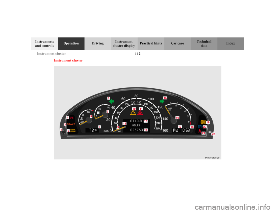
Instrument cluster
P54.30-3528-29
Page 116 of 430
113 Instrument cluster
Te ch n i c a l
data Instruments
and controlsOperationDrivingInstrument
cluster displayPractical hints Car care Index 1Knob for instrument cluster illumination,
seepage114
2Engine malfunction indicator lamp, see page 302
3Brake fluid low, parking brake engaged,
seepage313
4Supplemental restraint system (SRS) malfunction
indicator lamp, see page 305
5Coolant temperature gauge, see page 115
6Outside temperature indicator, see page 115
7Fuel gauge with reserve warning lamp, see page 305
8Left turn signal indicator lamp, see combination
switch, see page 162
9Speedometer, see page 116
10Electronic stability program (ESP) warning lamp,
system is adjusting to road conditions, see page 307
11Distance warning lamp – vehicles with Distronic
(DTR), distance to the vehicle ahead is insufficient,
see page 272 and 307
Vehicles without Distronic: It illuminates with the
electronic key in starter switch position 2. It should
go out when the engine is running.12Multifunction display, see page 118
Malfunction and warning messages in the
multifunction display, see page 309
13Trip odometer, see page 117 and 122
14Main odometer, see page 122
15Right turn signal indicator lamp, see combination
switch, page 162
16Tachometer, see page 117
17Gear range indicator display, see selector lever
positions, page 240
18Digital clock
To set the time, see COMAND operator’s manual
19Antilock brake system (ABS) malfunction indicator
lamp, see page 306
20High beam headlamp indicator,
see exterior lamp switch on page 158, and
combination switch on page 162
21Fasten seat belts, see page 308
22Reset button J, see page 114 and 117
Page 117 of 430
114 Instrument cluster
Te ch n i c a l
data Instruments
and controlsOperationDrivingInstrument
cluster displayPractical hints Car care Index
Activating instrument cluster display
The instrument cluster is activated by:
•Opening the door
1.
•Pressing button Jon the instrument cluster
1.
•Turning the electronic key in starter switch to
position 1 or 2.
•Switching on the exterior lamps.
1 The instrument cluster is activated for approximately 30 seconds.Instrument cluster illumination
The instrument cluster illumination is dimmed or
brightened automatically to suit daylight lighting
conditions.Display illumination, changing basic settings for driving
at dusk or in darkness:
Press adjusting knob (1) – the knob will pop out.
Rotate adjusting knob (1) clockwise – instrument lamp
intensity increases.
Rotate adjusting knob (1) counterclockwise –
instrument lamp intensity decreases.
Push knob back into panel.
Note:
It is not possible to select a basic brightness setting in
daylight – the intensity is adjusted automatically.
Page 118 of 430
115 Instrument cluster
Te ch n i c a l
data Instruments
and controlsOperationDrivingInstrument
cluster displayPractical hints Car care Index Coolant temperature gauge (5)
During severe operating conditions and stop-and-go city
traffic, the coolant temperature may rise close to the red
marking.
The engine should not be operated with the coolant
temperature in the red zone. Doing so may cause
serious engine damage which is not covered by the
Mercedes-Benz Limited Warranty.Outside temperature indicator (6)
The temperature sensor is located in the front bumper
area. Due to its location, the sensor can be affected by
road or engine heat during idling or slow driving. This
means that the accuracy of the displayed temperature
can only be verified by comparison to a thermometer
placed next to the sensor, not by comparison to external
displays (e.g. bank signs etc.).
Adaption to ambient temperature takes place in steps
and depends on the prevailing driving conditions (stop-
and-go or moderate, constant driving) and amount of
temperature change.
Note:
The unit for the temperature indicator display can be set
in the individual setting menu “INST. CLUSTER” –
“TEMP. INDICATOR” on page 140.
Wa r n i n g !
• Driving when your engine is badly overheated
can cause some fluids which may have leaked
into the engine compartment to catch fire. You
could be seriously burned.• Steam from an overheated engine can cause
serious burns and can occur just by opening
the engine hood. Stay away from the engine if
you see or hear steam coming from it. Turn off
the engine, get out of the vehicle and do not
stand near the vehicle until it cools down.
Wa r n i n g !
The outside temperature indicator is not designed
to serve as an Ice-Warning Device and is therefore
unsuitable for that purpose. Indicated
temperatures just above the freezing point do not
guarantee that the road surface is free of ice.
Page 119 of 430
116 Instrument cluster
Te ch n i c a l
data Instruments
and controlsOperationDrivingInstrument
cluster displayPractical hints Car care Index
Speedometer (9)
When the cruise control is activated, the segments on
the speedometer scale between the set speed to the top
of the scale are illuminated. Cruise control, see
page 258.
When the Distronic (DTR) is activated, one or two
segments around the speed stored in memory light up
in the speedometer dial. Distronic (DTR), see page 261.Note:
The speed display is set to read out for
•USA in mph
•Canada in km/h.
The unit for the speed display can be set in the
individual setting menu “INST. CLUSTER” –
“SPEEDOMETER” on page 140.
Page 120 of 430
117 Instrument cluster
Te ch n i c a l
data Instruments
and controlsOperationDrivingInstrument
cluster displayPractical hints Car care Index Trip odometer (13)
To reset to “0” miles / km:
Activate the instrument cluster if it is not already
activated by pressing theJbutton on the instrument
cluster.
Press the è or ÿ button on the multifunction
steering wheel repeatedly until the trip odometer
appears if it is not displayed. See page 122.
Press button Jon the instrument cluster until the trip
odometer is reset.Tachometer (16)
The red marking on the tachometer denotes excessive
engine speed.
Avoid this engine speed, as it may result in serious
engine damage that is not covered by the
Mercedes-Benz Limited Warranty.
To help protect the engine, the fuel supply is interrupted
if the engine is operated within the red marking.