MERCEDES-BENZ S430 2002 W220 Owner's Manual
Manufacturer: MERCEDES-BENZ, Model Year: 2002, Model line: S430, Model: MERCEDES-BENZ S430 2002 W220Pages: 430, PDF Size: 20.81 MB
Page 331 of 430
328 Malfunction and warning messages
Te ch n i c a l
data Instruments
and controlsOperation DrivingInstrument
cluster displayPractical hints Car care Index
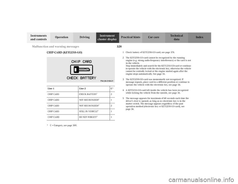
CHIP-CARD (KEYLESS-GO)
* C = Category, see page 309.1 Check battery of KEYLESS-GO-card, see page 374.
2 The KEYLESS-GO-card cannot be recognized by the running
engine (e.g. strong radio-frequency interference) or the card is not
in the vehicle.
Stop immediately and search for the KEYLESS-GO-card or continue
to operate the vehicle with the electronic key, otherwise the vehicle
cannot be centrally locked or the engine started again after the
engine stops automatically. See page 36.
3 The KEYLESS-GO-card was momentarily not recognized. If
message repeats, place card in a different position or continue to
operate the vehicle with the electronic key, see page 36.
4 A KEYLESS-GO-card left inside the vehicle has been recognized
while locking the vehicle from the outside, see page 36.
5 The message appears for maximum of 60 seconds each time the
driver’s door is opened, as long as no electronic key is in the
starter switch. The message appears regardless of the past
operation method (electronic key or KEYLESS-GO-card), see
page 36. Line 1 Line 2 C*
CHIP CARD CHECK BATTERY
1
2
CHIP CARD NOT RECOGNIZED!
2
1
CHIP CARD NOT RECOGNIZED!
3
2
CHIP CARD STILL IN VEHICLE
4
1
CHIP CARD DO NOT FORGET!
5
1
Page 332 of 430
329 Malfunction and warning messages
Te ch n i c a l
data Instruments
and controlsOperation DrivingInstrument
cluster displayPractical hints Car care Index SELECTOR LEVER
(Vehicles with KEYLESS-GO only)
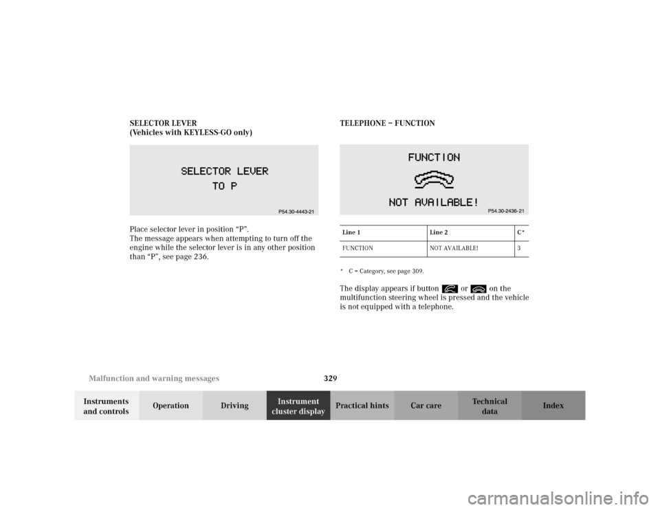
Place selector lever in position “P”.
The message appears when attempting to turn off the
engine while the selector lever is in any other position
than “P”, see page 236.TELEPHONE – FUNCTION
* C = Category, see page 309.The display appears if button í or ì on the
multifunction steering wheel is pressed and the vehicle
is not equipped with a telephone.Line 1 Line 2 C*
FUNCTION NOT AVAILABLE! 3
Page 333 of 430
330 Malfunction and warning messages
Te ch n i c a l
data Instruments
and controlsOperation DrivingInstrument
cluster displayPractical hints Car care Index
WA S H E R F L U I D
* C = Category, see page 309.
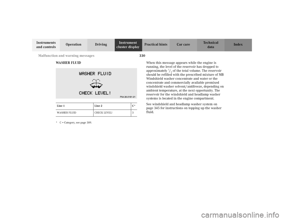
When this message appears while the engine is
running, the level of the reservoir has dropped to
approximately
1/3 of the total volume. The reservoir
should be refilled with the prescribed mixture of MB
Windshield washer concentrate and water or the
concentrate and commercially available premixed
windshield washer solvent / antifreeze, depending on
ambient temperature, at the next opportunity. The
reservoir for the windshield and headlamp washer
systems is located in the engine compartment.
See windshield and headlamp washer system on
page 345 for instructions on topping up the washer
fluid.
Line 1 Line 2 C*
WASHER FLUID CHECK LEVEL! 3
Page 334 of 430
331 Malfunction and warning messages
Te ch n i c a l
data Instruments
and controlsOperation DrivingInstrument
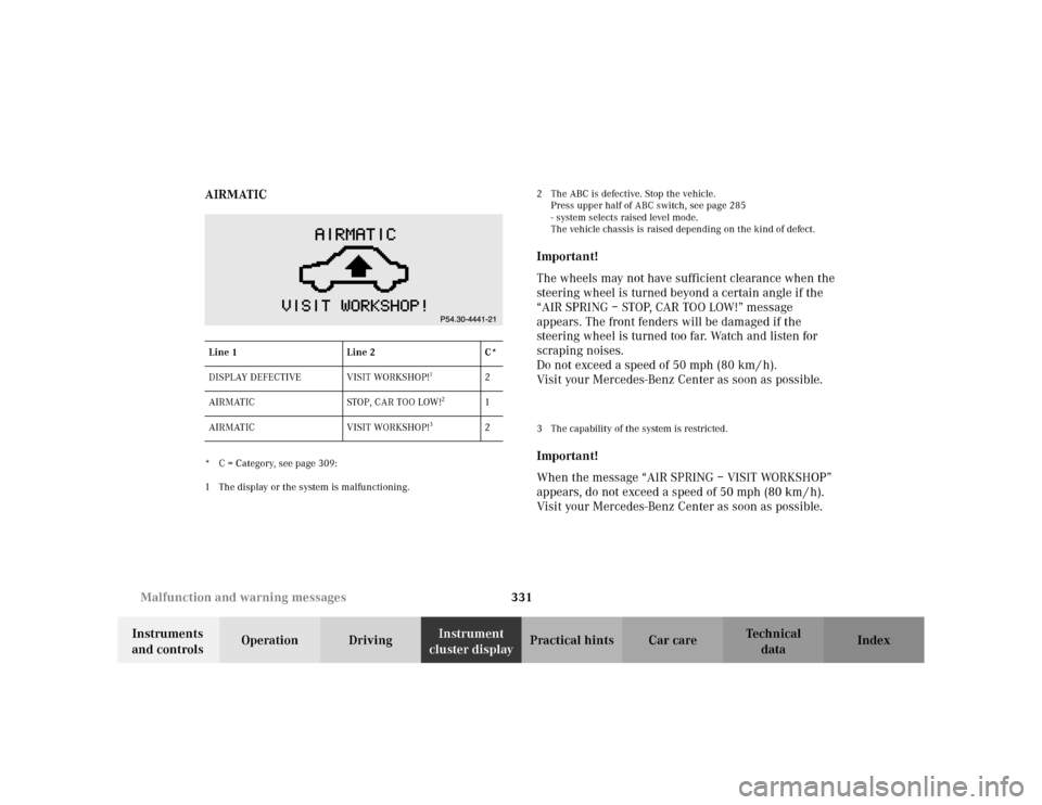
cluster displayPractical hints Car care Index AIRMATIC
* C = Category, see page 309:
1 The display or the system is malfunctioning.2 The ABC is defective. Stop the vehicle.
Press upper half of ABC switch, see page 285
- system selects raised level mode.
The vehicle chassis is raised depending on the kind of defect.
Important!
The wheels may not have sufficient clearance when the
steering wheel is turned beyond a certain angle if the
“AIR SPRING – STOP, CAR TOO LOW!” message
appears. The front fenders will be damaged if the
steering wheel is turned too far. Watch and listen for
scraping noises.
Do not exceed a speed of 50 mph (80 km / h).
Visit your Mercedes-Benz Center as soon as possible.3 The capability of the system is restricted.Important!
When the message “AIR SPRING – VISIT WORKSHOP”
appears, do not exceed a speed of 50 mph (80 km / h).
Visit your Mercedes-Benz Center as soon as possible.
Line 1 Line 2 C*
DISPLAY DEFECTIVE VISIT WORKSHOP!
1
2
AIRMATIC STOP, CAR TOO LOW!
2
1
AIRMATIC VISIT WORKSHOP!
3
2
Page 335 of 430
332 Malfunction and warning messages
Te ch n i c a l
data Instruments
and controlsOperation DrivingInstrument
cluster displayPractical hints Car care Index
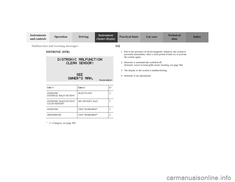
DISTRONIC (DTR)
* C = Category, see page 309.1 Due to the presence of electro-magnetic radiation, the system is
presently unavailable. After a short period of time try to activate
the system again.
2 Distronic is automatically switched off.
Distronic sensor in hood grille needs cleaning, see page 386.
3 The display or the system is malfunctioning.
4 Distronic is not operational.
Line 1 Line 2 C*
DISTRONIC
EXTERNAL MALFUNCTION
1
REACTIVATE! 2
DISTRONIC MALFUNCTION
CLEAN SENSOR!
2
SEE OWNER’S MAN. 2
DISTRONIC VISIT WORKSHOP!
3
2
SPEEDTRONIC VISIT WORKSHOP!
4
2
Page 336 of 430
333 Malfunction and warning messages
Te ch n i c a l
data Instruments
and controlsOperation DrivingInstrument
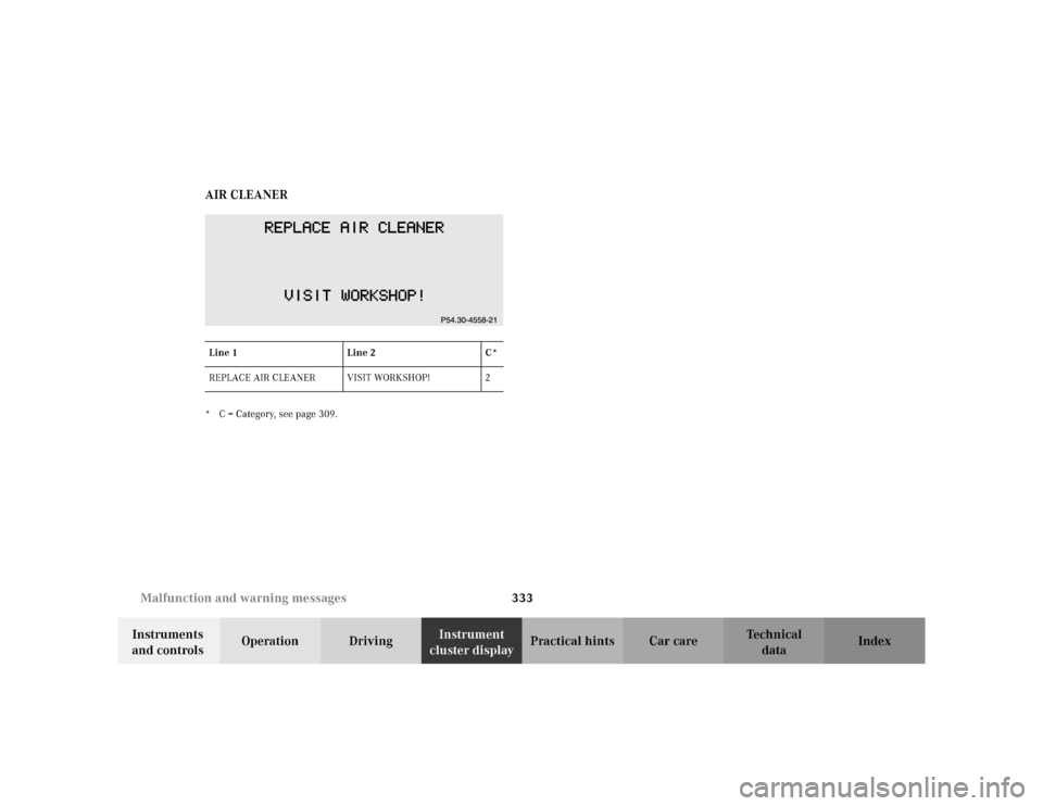
cluster displayPractical hints Car care Index AIR CLEANER
* C = Category, see page 309.Line 1 Line 2 C*
REPLACE AIR CLEANER VISIT WORKSHOP! 2
Page 337 of 430

Page 338 of 430
335 Contents – Practical hints
Te ch n i c a l
data Instruments
and controlsOperation DrivingInstrument
cluster displayPractical hintsCar care Index
Practical hintsFirst aid kit .....................................336
Stowing things in the vehicle ......336
Fuses ................................................337
Hood .................................................339
Checking engine oil level .............342
Automatic transmission
fluid level ...................................343
Active body control (ABC)
fluid level ...................................343
Coolant level ...................................344
Adding coolant ...........................344
Windshield and headlamp
washer system ...........................345
Windshield and headlamp
washer fluid mixing ratio .........345Spare wheel, vehicle tools,
storage compartment ............... 346
Vehicle jack .................................... 347
Wheels ............................................ 348
Tire Replacement ....................... 348
Rotating wheels ......................... 349
Spare wheel .................................... 349
Changing wheels ........................... 351
Tire inflation pressure ................. 356
Battery ............................................. 357
Jump starting ................................. 359
Towing the vehicle ........................ 361
Exterior lamps ............................... 364
Headlamp assembly .................. 365
Taillamp assemblies .................. 368Changing batteries in
the electronic key ..................... 371
Synchronizing
remote control ............................373
Changing batteries in the
KEYLESS-GO-card ..................... 374
Emergency engine
shut-down .................................. 376
Fuel filler flap,
manual release .......................... 376
Emergency operation of
sliding/pop-up roof ...................377
Replacing wiper blades .................378
Roof rack .........................................380
Page 339 of 430
336 First aid kit
Te ch n i c a l
data Instruments
and controlsOperation DrivingInstrument
cluster displayPractical hintsCar care Index
First aid kit
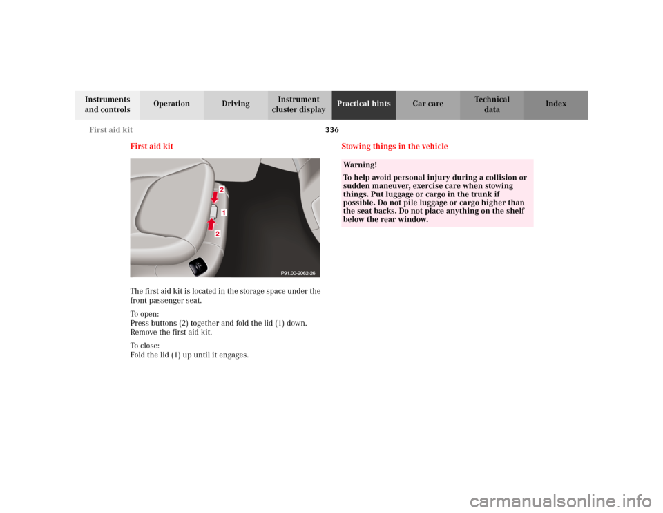
The first aid kit is located in the storage space under the
front passenger seat.
To o pen :
Press buttons (2) together and fold the lid (1) down.
Remove the first aid kit.
To c lo se:
Fold the lid (1) up until it engages.Stowing things in the vehicle
Wa r n i n g !
To help avoid personal injury during a collision or
sudden maneuver, exercise care when stowing
things. Put luggage or cargo in the trunk if
possible. Do not pile luggage or cargo higher than
the seat backs. Do not place anything on the shelf
below the rear window.
Page 340 of 430
337 Fuses
Te ch n i c a l
data Instruments
and controlsOperation DrivingInstrument
cluster displayPractical hintsCar care Index Fuses
Most of your vehicle’s electrical components are fused
with safety fuses. With the exception of the brake lights,
all individual lighting system components are
electronically fused. Before replacing a blown safety
fuse, determine the cause of the short circuit. Always
observe amperage and color of fuse.
The circuit for components is protected by a cycled
circuit breaker interrupted if too much current is being
drawn. The circuit closes automatically after a short
time; the circuit is broken again if the malfunction
reoccurs.
Always use a new fuse for replacement. Never attempt to
repair or bridge a blown fuse.
A fuse chart, spare fuses and a fuse extractor are located
in the vehicle tool kit in the luggage bowl under the
trunk floor. See page 346 for notes on the vehicle tool
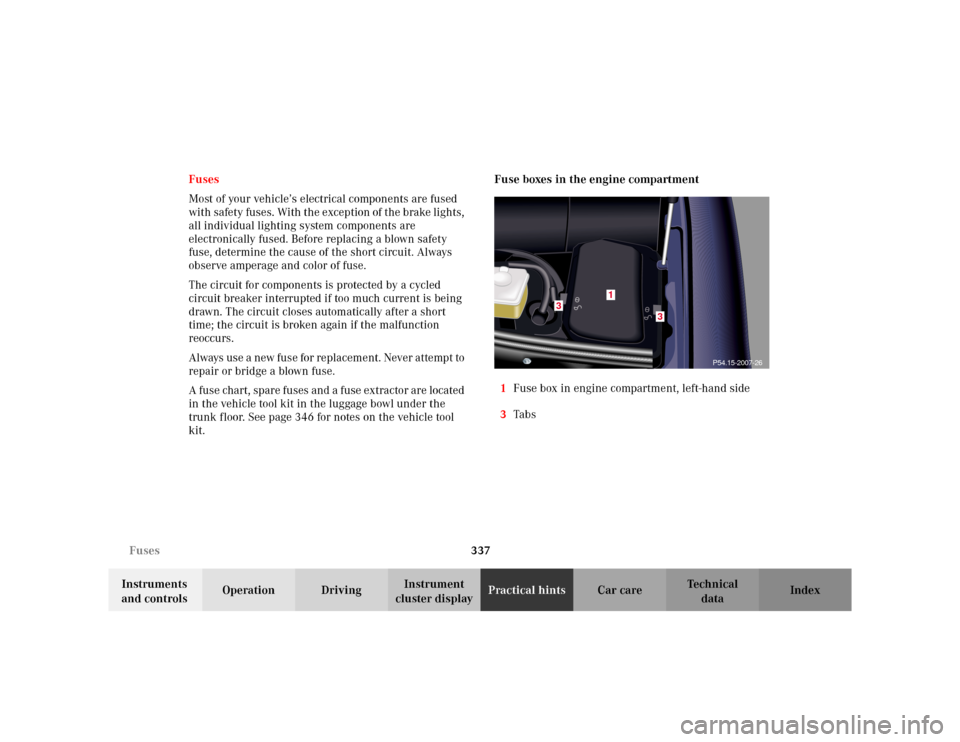
kit.Fuse boxes in the engine compartment
1Fuse box in engine compartment, left-hand side
3Ta b s
3
3
1
P54.15-2007-26