warning MERCEDES-BENZ S500 2002 W220 User Guide
[x] Cancel search | Manufacturer: MERCEDES-BENZ, Model Year: 2002, Model line: S500, Model: MERCEDES-BENZ S500 2002 W220Pages: 430, PDF Size: 20.81 MB
Page 85 of 430
82 Restraint systems
Te ch n i c a l
data Instruments
and controlsOperationDrivingInstrument
cluster displayPractical hints Car care Index
Seat belt nonusage warning system
With the electronic key in starter switch position 2, a
warning sounds for a short time if the driver’s seat belt
is not fastened.
Automatic comfort-fit seat belt:
An automatic comfort-fit feature for all seat belt is
activated when the electronic key in the starter switch is
turned to position 1 or 2.
The retraction force of the inertia reel is reduced,
increasing the level of seat belt comfort.
Note:
For cleaning and care of the seat belts see page 389.
Wa r n i n g !
Never ride in a moving vehicle with the backrest
reclined. Sitting in an excessively reclined position
can be dangerous. You could slide under the seat
belt in a collision. If you slide under it, the belt
would apply force at the abdomen or neck. That
could cause serious or even fatal injuries. The
backrest and seat belt provide the best restraint
when the wearer is in an upright position and the
belt is properly positioned on the body.
Page 102 of 430

99 Restraint systems
Te ch n i c a l
data Instruments
and controlsOperationDrivingInstrument
cluster displayPractical hints Car care Index Infant and child restraint systems
We recommend all infants and children be properly
restrained at all times while the vehicle is in motion. All
lap-shoulder belts except the driver’s seat belt have
special seat belt retractors for secure fastening of child
restraints.
To activate, pull shoulder belt out completely and let it
retract. During the seat belt retraction a ratcheting
sound can be heard to indicate that the special seat belt
retractor is activated. The belt is now locked.
To deactivate, release seat belt buckle and let seat belt
retract completely. The seat belt can again be used in
the usual manner
Note:
For child seats with mounting fittings for tether
anchorages refer to page 101 (installation of infant and
child restraint systems).Important!
The use of infant or child restraints is required by law in
all 50 states and all Canadian provinces.
Infants and small children should be seated in an
appropriate infant or child restraint system properly
secured by a lap-shoulder belt, and that complies with
U.S. Federal Motor Vehicle Safety Standard 213 and
Canadian Motor Vehicle Safety Standard 213.
A statement by the child restraint manufacturer of
compliance with this standard can be found on the
instruction label on the restraint and in the instruction
manual provided with the restraint.
When using any infant or child restraint system, be sure
to carefully read and follow all manufacturer’s
instructions for installation and use.
Please read and observe warning labels affixed to inside
of vehicle and to infant or child restraints.
Wa r n i n g !
Never release the seat belt buckle while vehicle is
in motion, since the special seat belt retractor will
be deactivated.
Page 116 of 430
113 Instrument cluster
Te ch n i c a l
data Instruments
and controlsOperationDrivingInstrument
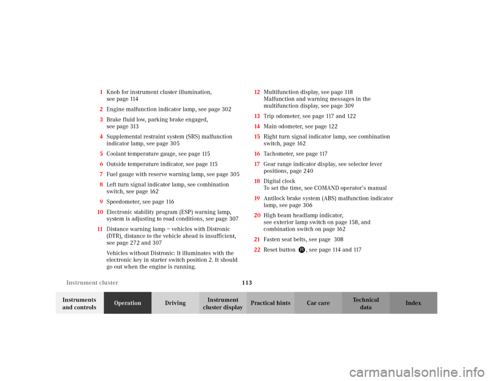
cluster displayPractical hints Car care Index 1Knob for instrument cluster illumination,
seepage114
2Engine malfunction indicator lamp, see page 302
3Brake fluid low, parking brake engaged,
seepage313
4Supplemental restraint system (SRS) malfunction
indicator lamp, see page 305
5Coolant temperature gauge, see page 115
6Outside temperature indicator, see page 115
7Fuel gauge with reserve warning lamp, see page 305
8Left turn signal indicator lamp, see combination
switch, see page 162
9Speedometer, see page 116
10Electronic stability program (ESP) warning lamp,
system is adjusting to road conditions, see page 307
11Distance warning lamp – vehicles with Distronic
(DTR), distance to the vehicle ahead is insufficient,
see page 272 and 307
Vehicles without Distronic: It illuminates with the
electronic key in starter switch position 2. It should
go out when the engine is running.12Multifunction display, see page 118
Malfunction and warning messages in the
multifunction display, see page 309
13Trip odometer, see page 117 and 122
14Main odometer, see page 122
15Right turn signal indicator lamp, see combination
switch, page 162
16Tachometer, see page 117
17Gear range indicator display, see selector lever
positions, page 240
18Digital clock
To set the time, see COMAND operator’s manual
19Antilock brake system (ABS) malfunction indicator
lamp, see page 306
20High beam headlamp indicator,
see exterior lamp switch on page 158, and
combination switch on page 162
21Fasten seat belts, see page 308
22Reset button J, see page 114 and 117
Page 118 of 430
115 Instrument cluster
Te ch n i c a l
data Instruments
and controlsOperationDrivingInstrument
cluster displayPractical hints Car care Index Coolant temperature gauge (5)
During severe operating conditions and stop-and-go city
traffic, the coolant temperature may rise close to the red
marking.
The engine should not be operated with the coolant
temperature in the red zone. Doing so may cause
serious engine damage which is not covered by the
Mercedes-Benz Limited Warranty.Outside temperature indicator (6)
The temperature sensor is located in the front bumper
area. Due to its location, the sensor can be affected by
road or engine heat during idling or slow driving. This
means that the accuracy of the displayed temperature
can only be verified by comparison to a thermometer
placed next to the sensor, not by comparison to external
displays (e.g. bank signs etc.).
Adaption to ambient temperature takes place in steps
and depends on the prevailing driving conditions (stop-
and-go or moderate, constant driving) and amount of
temperature change.
Note:
The unit for the temperature indicator display can be set
in the individual setting menu “INST. CLUSTER” –
“TEMP. INDICATOR” on page 140.
Wa r n i n g !
• Driving when your engine is badly overheated
can cause some fluids which may have leaked
into the engine compartment to catch fire. You
could be seriously burned.• Steam from an overheated engine can cause
serious burns and can occur just by opening
the engine hood. Stay away from the engine if
you see or hear steam coming from it. Turn off
the engine, get out of the vehicle and do not
stand near the vehicle until it cools down.
Wa r n i n g !
The outside temperature indicator is not designed
to serve as an Ice-Warning Device and is therefore
unsuitable for that purpose. Indicated
temperatures just above the freezing point do not
guarantee that the road surface is free of ice.
Page 136 of 430
133 Multifunction steering wheel, multifunction display
Te ch n i c a l
data Instruments
and controlsOperationDrivingInstrument
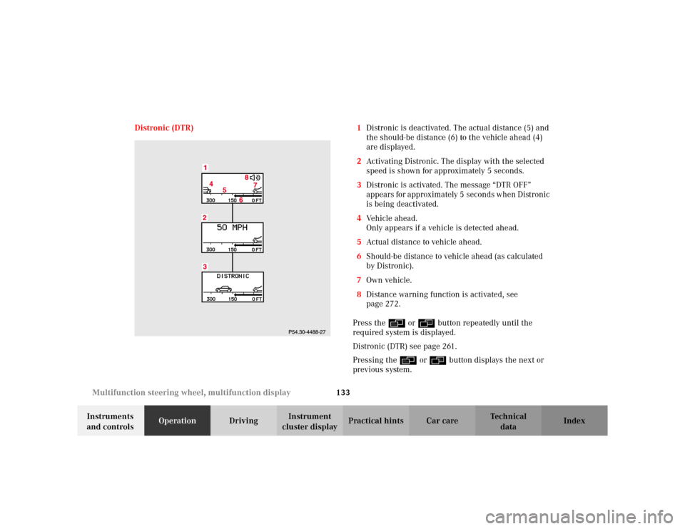
cluster displayPractical hints Car care Index Distronic (DTR) 1Distronic is deactivated. The actual distance (5) and
the should-be distance (6) to the vehicle ahead (4)
are displayed.
2Activating Distronic. The display with the selected
speed is shown for approximately 5 seconds.
3Distronic is activated. The message “DTR OFF”
appears for approximately 5 seconds when Distronic
is being deactivated.
4Vehicle ahead.
Only appears if a vehicle is detected ahead.
5Actual distance to vehicle ahead.
6Should-be distance to vehicle ahead (as calculated
by Distronic).
7Own vehicle.
8Distance warning function is activated, see
page 272.
Press the è or ÿ button repeatedly until the
required system is displayed.
Distronic (DTR) see page 261.
Pressing the è or ÿ button displays the next or
previous system.
Page 139 of 430

136 Multifunction steering wheel, multifunction display
Te ch n i c a l
data Instruments
and controlsOperationDrivingInstrument
cluster displayPractical hints Car care Index
Malfunction /warning message memory
1There are no messages stored in the system.
2Number of messages stored in the system.Press the è or ÿ button repeatedly until the
message memory (1 or 2) is displayed.
Press the j or k button if display (2) appears.
The stored messages will now be displayed in order.
See page 309 for malfunction and warning messages.
Display (2) will reappear after you have scanned all the
malfunction and warning messages.
Should any malfunction or warning messages be stored
while driving, they will reappear in the display (2) when
the electronic key in starter switch is turned to
position 0 or removed from the starter switch.
The malfunction or warning messages will now be
displayed for approximately 5 seconds each. Pressing
the Jbutton in the instrument cluster displays the
next malfunction and warning message immediately.
The message memory will be cleared when the
electronic key is turned in the starter switch to
position 1 or 2. Should any subsequent faults occur,
they will be displayed in the message memory.
Pressing the è or ÿ button displays the next or
previous system.
Page 140 of 430
137 Multifunction steering wheel, multifunction display
Te ch n i c a l
data Instruments
and controlsOperationDrivingInstrument
cluster displayPractical hints Car care Index Important!
Malfunction and warning messages are only indicated
for certain systems and displayed to a low level of detail.
The malfunction and warning messages are simply a
reminder with respect to the operation of certain
systems and do not replace the driver’s responsibility to
maintain the vehicle’s operating safety by having all
required maintenance and safety checks performed on
the vehicle and by bringing the vehicle to an authorized
Mercedes-Benz Center to address the malfunction and
warning messages. See page 309.
Page 152 of 430

149 Flexible service system
Te ch n i c a l
data Instruments
and controlsOperationDrivingInstrument
cluster displayPractical hints Car care Index Flexible service system (FSS)
(service indicator)
The FSS permits a flexible service schedule that is
directly related to the operating conditions of the
vehicle.
The symbol 9 or ½ appears together with a
message in the multifunction display prior to the next
suggested service.
Depending on operating conditions throughout the year,
the next service is calculated and displayed in days or
distance remaining.The message is displayed for approximately 10 seconds
when turning the electronic key in starter switch to
position 2, or while driving when reaching the service
warning threshold.
The symbols and messages indicate the type of service
to be performed:
9Service A
½Service B
One of the following messages will appear in the display
(e.g. Service A):
“SERVICE A – IN xx DAYS”
“SERVICE A – IN xx MILES” (Canada: KM)
“SERVICE A – EXCEEDED BY xx DAYS”
“SERVICE A – EXCEEDED BY xx MILES” (Canada: KM)
“SERVICE A – PERFORM SERVICE”
The next service due date is displayed either in days or
in miles, depending on your driving style.
Once the suggested service term has passed, the symbol
and message appear for approximately 30 seconds and
a signal sounds every time when turning the electronic
key in starter switch to position 2.
P54.30-2768-26
Page 155 of 430
152 Tire inflation pressure monitor
Te ch n i c a l
data Instruments
and controlsOperationDrivingInstrument
cluster displayPractical hints Car care Index
Tire inflation pressure monitor (optional for Canada)
The tire inflation pressure, as selected by the driver, is
monitored in all four wheels on the ground. A warning
is issued to the driver in the case of a decrease in the
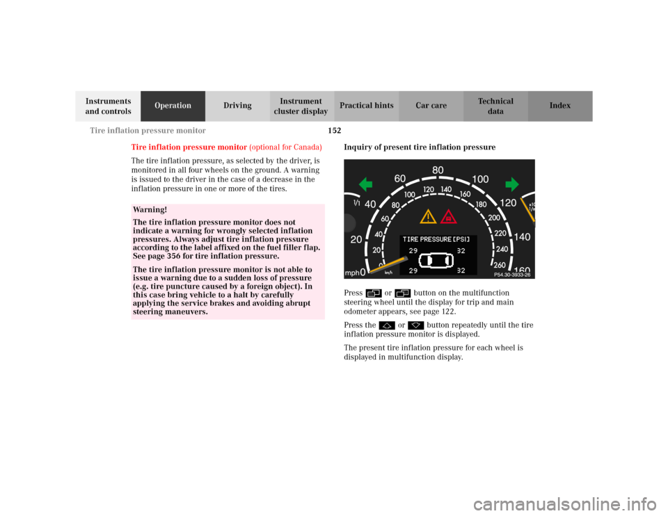
inflation pressure in one or more of the tires.Inquiry of present tire inflation pressure
Press è or ÿ button on the multifunction
steering wheel until the display for trip and main
odometer appears, see page 122.
Press the j or k button repeatedly until the tire
inflation pressure monitor is displayed.
The present tire inflation pressure for each wheel is
displayed in multifunction display.
Wa r n i n g !
The tire inflation pressure monitor does not
indicate a warning for wrongly selected inflation
pressures. Always adjust tire inflation pressure
according to the label affixed on the fuel filler flap.
See page 356 for tire inflation pressure.The tire inflation pressure monitor is not able to
issue a warning due to a sudden loss of pressure
(e.g. tire puncture caused by a foreign object). In
this case bring vehicle to a halt by carefully
applying the service brakes and avoiding abrupt
steering maneuvers.
Page 158 of 430

155 Tire inflation pressure monitor
Te ch n i c a l
data Instruments
and controlsOperationDrivingInstrument
cluster displayPractical hints Car care Index Notes:
To ensure proper functioning of the tire inflation
pressure monitor, the tire inflation pressure should be
checked and corrected according to the label affixed
inside the fuel filler flap. For a detailed description,
refer to page 356.
The message “REACTIVATE – TIRE PRESS. MONITOR”
appears if the tire inflation pressure shows an increase
of 4.4 psi (0.3 bar) or more. Reactivate the tire inflation
pressure monitor.
The tire inflation pressure monitor only functions on
wheels equipped with the proper electronic sensors.
Inquire at your authorized Mercedes-Benz Center about
retrofitting other than original Mercedes-Benz wheels
with electronic sensors.
Transporting a deflated road wheel in the vehicle, e.g.
after having a flat, the tire inflation pressure monitor
should only be activated once the flat tire and rim are
removed from the vehicle.To prevent possible damage to the electronic sensors,
have tire changes only performed at an authorized
Mercedes-Benz Center.
For malfunction and warning messages, see page 309.
When checking the tire inflation pressure of the road
wheels, also check the spare tire.
The tire inflation pressure of the spare wheel, mounted
or not mounted, is not monitored by the tire inflation
pressure monitor.
See page 346 for location of the spare wheel, and
page 356 for tire inflation pressure.