MERCEDES-BENZ S55AMG 2000 W220 Owner's Manual
Manufacturer: MERCEDES-BENZ, Model Year: 2000, Model line: S55AMG, Model: MERCEDES-BENZ S55AMG 2000 W220Pages: 421, PDF Size: 20.52 MB
Page 281 of 421
278 Driving systems
Te ch n ica l
data Instruments
and controlsOperationDrivingInstrument
cluster displayPractical hints Car care Index
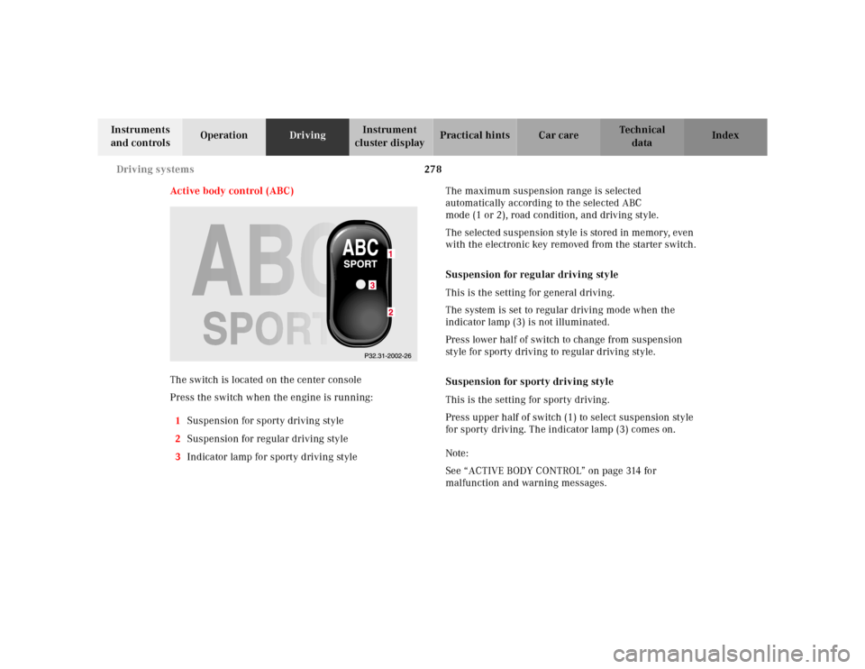
Active body control (ABC)
The switch is located on the center console
Press the switch when the engine is running:
1Suspension for sporty driving style
2Suspension for regular driving style
3Indicator lamp for sporty driving styleThe maximum suspension range is selected
automatically according to the selected ABC
mode (1 or 2), road condition, and driving style.
The selected suspension style is stored in memory, even
with the electronic key removed from the starter switch.
Suspension for regular driving style
This is the setting for general driving.
The system is set to regular driving mode when the
indicator lamp (3) is not illuminated.
Press lower half of switch to change from suspension
style for sporty driving to regular driving style.
Suspension for sporty driving style
This is the setting for sporty driving.
Press upper half of switch (1) to select suspension style
for sporty driving. The indicator lamp (3) comes on.
Note:
See “ACTIVE BODY CONTROL” on page 314 for
malfunction and warning messages.
Page 282 of 421
279 Driving systems
Te ch n ica l
data Instruments
and controlsOperationDrivingInstrument
cluster displayPractical hints Car care Index Level control system for vehicles with
Airmatic system
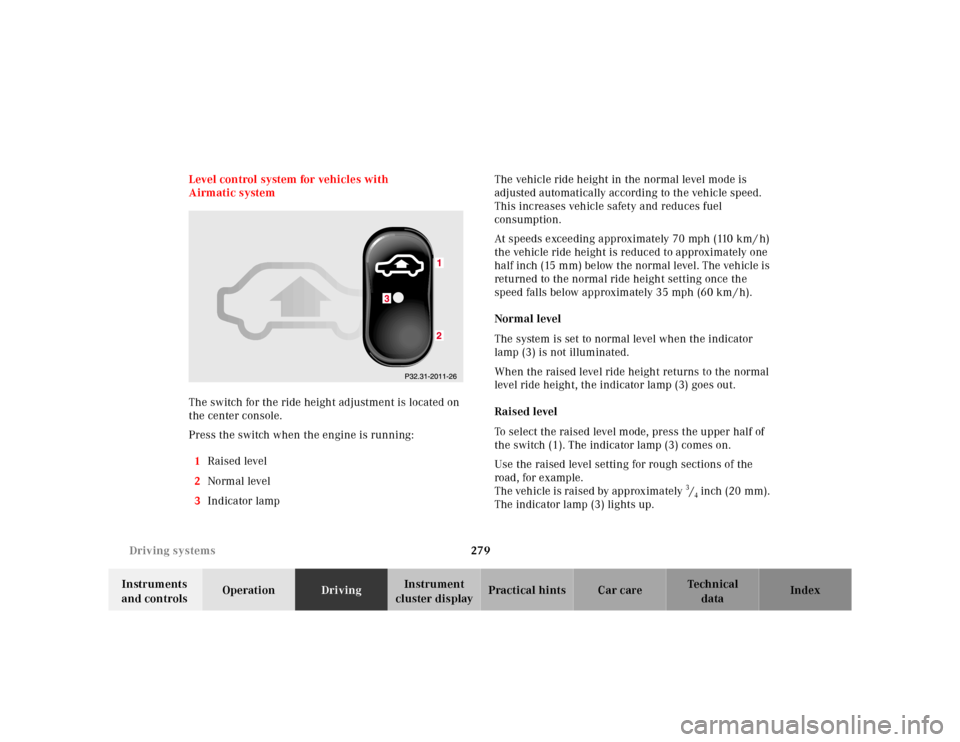
The switch for the ride height adjustment is located on
the center console.
Press the switch when the engine is running:
1Raised level
2Normal level
3Indicator lampThe vehicle ride height in the normal level mode is
adjusted automatically according to the vehicle speed.
This increases vehicle safety and reduces fuel
consumption.
At speeds exceeding approximately 70 mph (110 km / h)
the vehicle ride height is reduced to approximately one
half inch (15 mm) below the normal level. The vehicle is
returned to the normal ride height setting once the
speed falls below approximately 35 mph (60 km / h).
Normal level
The system is set to normal level when the indicator
lamp (3) is not illuminated.
When the raised level ride height returns to the normal
level ride height, the indicator lamp (3) goes out.
Raised level
To select the raised level mode, press the upper half of
the switch (1). The indicator lamp (3) comes on.
Use the raised level setting for rough sections of the
road, for example.
The vehicle is raised by approximately 3/4 inch (20 mm).
The indicator lamp (3) lights up.
Page 283 of 421
280 Driving systems
Te ch n ica l
data Instruments
and controlsOperationDrivingInstrument
cluster displayPractical hints Car care Index
The message “AIR SPRING – VEHICLE RISING” appears
in the multifunction display. The display switches off
when the vehicle is raised.
Notes:
The raised level setting switches off at speeds exceeding
approximately 75 mph (120 km / h), or if vehicle speed
is operated between 50 mph (80 km / h) and 75 mph
(120 km / h) for approximately 5 minutes. The message
“AIR SPRING – LEVEL CANCELLED” appears in the
display.
The raised level setting will be stored in memory after
the electronic key is removed from the starter switch if
you did not drive at the aforementioned speeds.
See “AIR SPRING” on page 325 for malfunction and
warning messages.Level control system for vehicles with
Active Body Control (ABC)
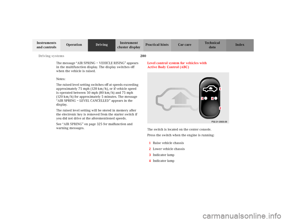
The switch is located on the center console.
Press the switch when the engine is running:
1Raise vehicle chassis
2Lower vehicle chassis
3Indicator lamp
4Indicator lamp
Page 284 of 421
281 Driving systems
Te ch n ica l
data Instruments
and controlsOperationDrivingInstrument
cluster displayPractical hints Car care Index The vehicle chassis ride height is raised or lowered
automatically according to the selected setting and to
the vehicle speed. This helps to increase vehicle
handling safety and lowers fuel consumption.
The selected setting is stored in memory, even with the
electronic key removed from the starter switch.
Note:
See “ACTIVE BODY CONTROL” on page 314 for
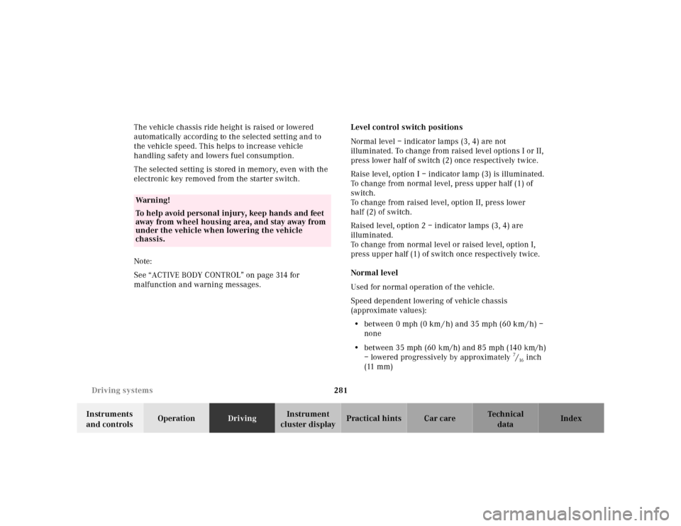
malfunction and warning messages.Level control switch positions
Normal level – indicator lamps (3, 4) are not
illuminated. To change from raised level options I or II,
press lower half of switch (2) once respectively twice.
Raise level, option I – indicator lamp (3) is illuminated.
To change from normal level, press upper half (1) of
switch.
To change from raised level, option II, press lower
half (2) of switch.
Raised level, option 2 – indicator lamps (3, 4) are
illuminated.
To change from normal level or raised level, option I,
press upper half (1) of switch once respectively twice.
Normal level
Used for normal operation of the vehicle.
Speed dependent lowering of vehicle chassis
(approximate values):
•between 0 mph (0 km / h) and 35 mph (60 km / h) –
none
•between 35 mph (60 km/h) and 85 mph (140 km/h)
– lowered progressively by approximately
7/16inch
(11 mm)
Wa r n i n g !
To help avoid personal injury, keep hands and feet
away from wheel housi ng area , an d stay away from
under the vehicle when lowering the vehicle
chassis.
Page 285 of 421

282 Driving systems
Te ch n ica l
data Instruments
and controlsOperationDrivingInstrument
cluster displayPractical hints Car care Index
Raised level, option I
This setting should be used when road surface
conditions are rough and must be used when driving
with snow chains mounted.
Important!
Driving with snow chains requires increased space
between tire and wheel housing. Refer to page 249 for
driving with snow chains.
Speed dependent lowering of vehicle chassis
(approximate values):
•at standstill – raised by approximately
3/4 inch
(20 mm)
•between 35 mph (60 km / h) and 120 mph
(190 km / h) – lowered progressively by
approximately one inch (25 mm)Raised level, option II
This setting should be used when road surface
conditions are very rough for increased ground
clearance.
Speed dependent lowering of vehicle chassis
(approximate values):
•at standstill - raised by approximately one and one
eight inch (30 mm)
•between 0 mph (0 km / h) and 35 mph (6o km / h) -
lowered progressively by approximately
3/8 inch
(10 mm)
•between 35 mph (60 km / h) and 120 mph
(190 km / h) – lowered progressively by
approximately one inch (25 mm)
Page 286 of 421
283 Driving systems
Te ch n ica l
data Instruments
and controlsOperationDrivingInstrument
cluster displayPractical hints Car care Index Adaptive damping system (ADS)
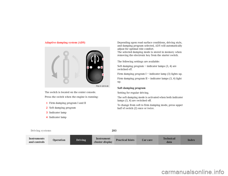
The switch is located on the center console.
Press the switch when the engine is running:
1Firm damping program I and II
2Soft damping program
3Indicator lamp
4Indicator lamp Depending upon road surface conditions, driving style,
and damping program selected, ADS will automatically
adjust for optimal ride comfort.
The selected damping mode is stored in memory when
removing the electronic key from the starter switch.
The following settings are available:
Soft damping program – indicator lamps (3, 4) are
switched off.
Firm damping program I – indicator lamp (3) lights up.
Firm damping program II – indicator lamps (3, 4) light
up.
Soft damping program
Setting for regular driving.
The soft damping mode is activated when both indicator
lamps (3, 4) are switched off.
To change from soft to firm damping mode, press upper
half of switch (2) once or twice.
P32.31-2010-26
Page 287 of 421

284 Driving systems
Te ch n ica l
data Instruments
and controlsOperationDrivingInstrument
cluster displayPractical hints Car care Index
Firm damping program I
Setting for sporty driving.
Changing from soft damping program:
Press upper half of switch (1) once. The indicator
lamp (3) lights up.
Changing from firm damping program II:
Press lower half of switch (2). The indicator lamp (4)
goes out.Firm damping program II
Setting for very sporty driving.
Changing from soft damping:
Press upper half of switch (1) twice. The indicator
lamps (3, 4) light up.
Changing from firm damping program I:
Press upper half of switch (1) once. The indicator
lamp (4) lights up in addition to indicator lamp (3).
Page 288 of 421
285 Parking system
Te ch n ica l
data Instruments
and controlsOperationDrivingInstrument
cluster displayPractical hints Car care Index Parking assist (Parktronic)
The Parktronic system assists the driver during parking
maneuvers. It visually and audibly indicates the relative
distance between the vehicle and an obstacle.
The front area of the vehicle is monitored when driving
forward. When reversing or with the gear selector lever
in position “N”, the front as well as the rear areas are
monitored.
With the electronic key in starter switch position 2,
Parktronic engages automatically at speeds up to
approximately 10 mph (15 km / h) and deactivates
during higher speeds.
Parktronic can be switched off by a control switch
located in the center console. It engages automatically
again when starting the engine.
See page 289 for Parktronic switch.
Wa r n i n g !
Parktronic is a supplemental system. It is not
intended to nor does it replace the need for extreme
care. The responsibility during parking and other
critical maneuvers rests always with the driver.Special attention must be paid to objects having
smooth surfaces or low silhouettes (e.g. trailer
couplings, painted posts, or street curbs). Such
objects may not be detected by the system and can
damage the vehicle.The operational function of the Parktronic can be
affected by dirty sensors, especially at times of
snow and ice. See page 378 for notes on cleaning
the parktronic system sensors.Interference caused by other ultrasonic signals
(e.g. working jackhammers or the air brakes of
trucks) can cause the system to send erratic
indications, and should be taken into
consideration.
Page 289 of 421
286 Parking system
Te ch n ica l
data Instruments
and controlsOperationDrivingInstrument
cluster displayPractical hints Car care Index
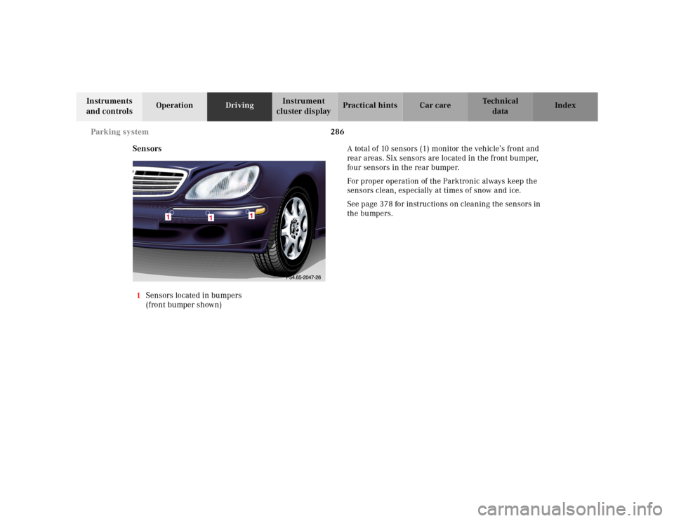
Sensors
1Sensors located in bumpers
(front bumper shown)A total of 10 sensors (1) monitor the vehicle’s front and
rear areas. Six sensors are located in the front bumper,
four sensors in the rear bumper.
For proper operation of the Parktronic always keep the
sensors clean, especially at times of snow and ice.
See page 378 for instructions on cleaning the sensors in
the bumpers.
Page 290 of 421
287 Parking system
Te ch n ica l
data Instruments
and controlsOperationDrivingInstrument
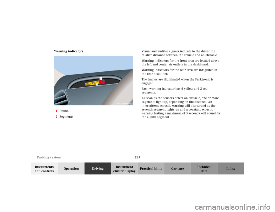
cluster displayPractical hints Car care Index Warning indicators
1Frame
2SegmentsVisual and audible signals indicate to the driver the
relative distance between the vehicle and an obstacle.
Warning indicators for the front area are located above
the left and center air outlets in the dashboard.
Warning indicators for the rear area are integrated in
the rear headliner.
The frames are illuminated when the Parktronic is
engaged.
Each warning indicator has 6 yellow and 2 red
segments.
As soon as the sensors detect an obstacle, one or more
segments light up, depending on the distance. An
intermittent acoustic warning will also sound as the
seventh segment lights up and a constant acoustic
warning lasting a maximum of 3 seconds will sound for
the eighth segment.
2
1
P54.26-0319-26