sensor MERCEDES-BENZ S55AMG 2002 W220 User Guide
[x] Cancel search | Manufacturer: MERCEDES-BENZ, Model Year: 2002, Model line: S55AMG, Model: MERCEDES-BENZ S55AMG 2002 W220Pages: 430, PDF Size: 20.81 MB
Page 270 of 430
267 Driving systems
Te ch n i c a l
data Instruments
and controlsOperationDrivingInstrument
cluster displayPractical hints Car care Index Driving with Distronic activated
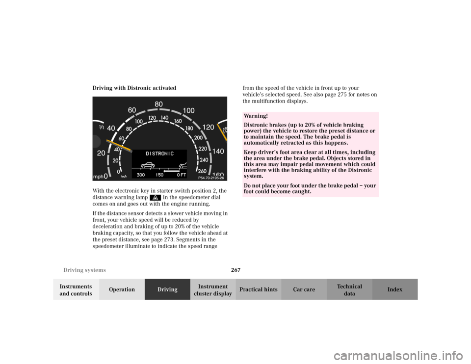
With the electronic key in starter switch position 2, the
distance warning lampl in the speedometer dial
comes on and goes out with the engine running.
If the distance sensor detects a slower vehicle moving in
front, your vehicle speed will be reduced by
deceleration and braking of up to 20% of the vehicle
braking capacity, so that you follow the vehicle ahead at
the preset distance, see page 273. Segments in the
speedometer illuminate to indicate the speed range from the speed of the vehicle in front up to your
vehicle’s selected speed. See also page 275 for notes on
the multifunction displays.
Wa r n i n g !
Distronic brakes (up to 20% of vehicle braking
power) the vehicle to restore the preset distance or
to maintain the speed. The brake pedal is
automatically retracted as this happens.Keep driver’s foot area clear at all times, including
the area under the brake pedal. Objects stored in
this area may impair pedal movement which could
interfere with the braking ability of the Distronic
system.Do not place your foot under the brake pedal – your
foot could become caught.
Page 272 of 430
269 Driving systems
Te ch n i c a l
data Instruments
and controlsOperationDrivingInstrument
cluster displayPractical hints Car care Index Additional driving hints
Important!
When starting the engine, Distronic goes through an
initialization and self-test phase – this can take up to
2minutes.
The most likely cause for a malfunctioning system is a
dirty sensor (located behind the hood grille), especially
at times of snow and ice or heavy rain. In such a case,
Distronic will switch off, and the message
“DISTRONIC – CLEAN SENSOR!” appears in the
multifunction display.
For cleaning and care of the Distronic sensor, see
page 386.
Restart the engine after cleaning the sensor.
The following are some sample situations which may
influence the functions of Distronic.
Wa r n i n g !
Distronic works to maintain the speed selected by
the driver unless a moving obstacle proceeding
directly ahead of it in the same travel direction is
detected (e.g. following another vehicle ahead at a
distance set by Distronic). This means that:• your vehicle can pass another vehicle after you
change lanes,• while in a sharp turn or if the vehicle in front
is in a sharp turn, Distronic could lose sight of
a vehicle traveling in front of it, then your
vehicle could accelerate to the previously
selected speed.Distronic regulates only the distance between your
vehicle and those directly ahead, but does not
register stationary objects in the roadway, e.g.:
• a stopped vehicle in a traffic jam,
• a disabled vehicle,
• an oncoming vehicle.
The driver must always be on the alert and observe
all traffic and intercede with steering and braking
inputs as necessary.Wa r n i n g !
Distronic should not be used in snowy or icy road
conditions.
Page 294 of 430
291 Parking system
Te ch n i c a l
data Instruments
and controlsOperationDrivingInstrument
cluster displayPractical hints Car care Index Parking assist (Parktronic)
(optional, standard on model S 600)
The Parktronic system assists the driver during parking
maneuvers. It visually and audibly indicates the relative
distance between the vehicle and an obstacle.
The front area of the vehicle is monitored when driving
forward. When reversing or with the gear selector lever
in position “N”, the front as well as the rear areas are
monitored.
With the electronic key in starter switch position 2,
Parktronic engages automatically at speeds up to
approximately 10 mph (15 km / h) and deactivates
during higher speeds.
Parktronic can be switched off by a control switch
located in the center console. It engages automatically
again when starting the engine.
See page 295 for Parktronic switch.
Wa r n i n g !
Parktronic is a supplemental system. It is not
intended to nor does it replace the need for extreme
care. The responsibility during parking and other
critical maneuvers rests always with the driver.Special attention must be paid to objects having
smooth surfaces or low silhouettes (e.g. trailer
couplings, painted posts, or street curbs). Such
objects may not be detected by the system and can
damage the vehicle.The operational function of the Parktronic can be
affected by dirty sensors, especially at times of
snow and ice. See page 386 for notes on cleaning
the parktronic system sensors.Interference caused by other ultrasonic signals
(e.g. working jackhammers or the air brakes of
trucks) can cause the system to send erratic
indications, and should be taken into
consideration.
Page 295 of 430
292 Parking system
Te ch n i c a l
data Instruments
and controlsOperationDrivingInstrument
cluster displayPractical hints Car care Index
Sensors
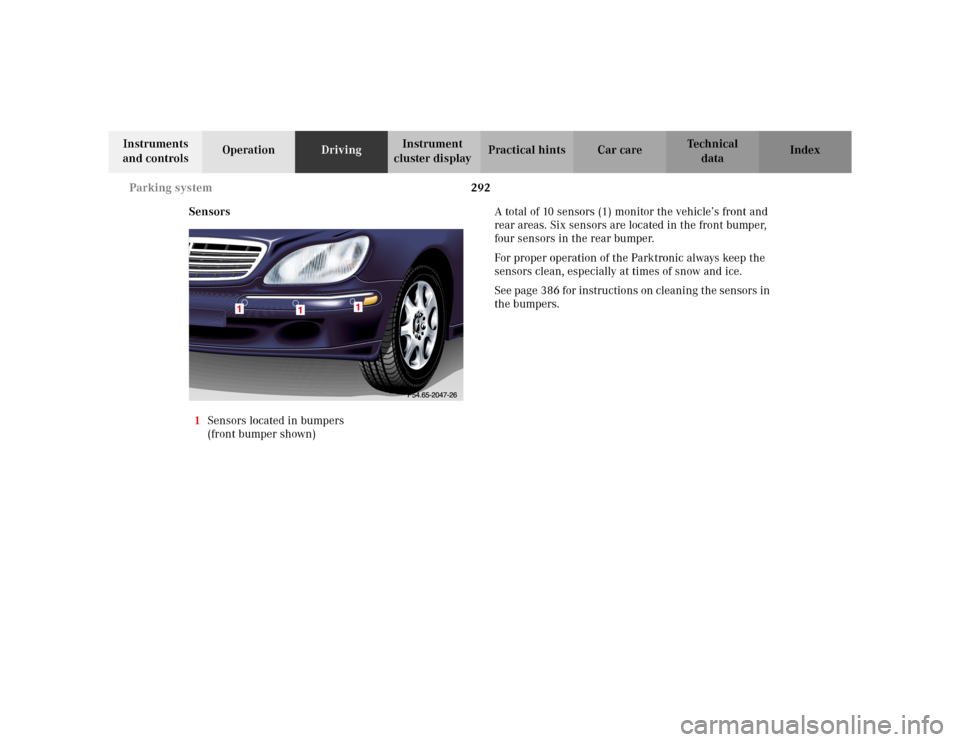
1Sensors located in bumpers
(front bumper shown)A total of 10 sensors (1) monitor the vehicle’s front and
rear areas. Six sensors are located in the front bumper,
four sensors in the rear bumper.
For proper operation of the Parktronic always keep the
sensors clean, especially at times of snow and ice.
See page 386 for instructions on cleaning the sensors in
the bumpers.
Page 296 of 430
293 Parking system
Te ch n i c a l
data Instruments
and controlsOperationDrivingInstrument
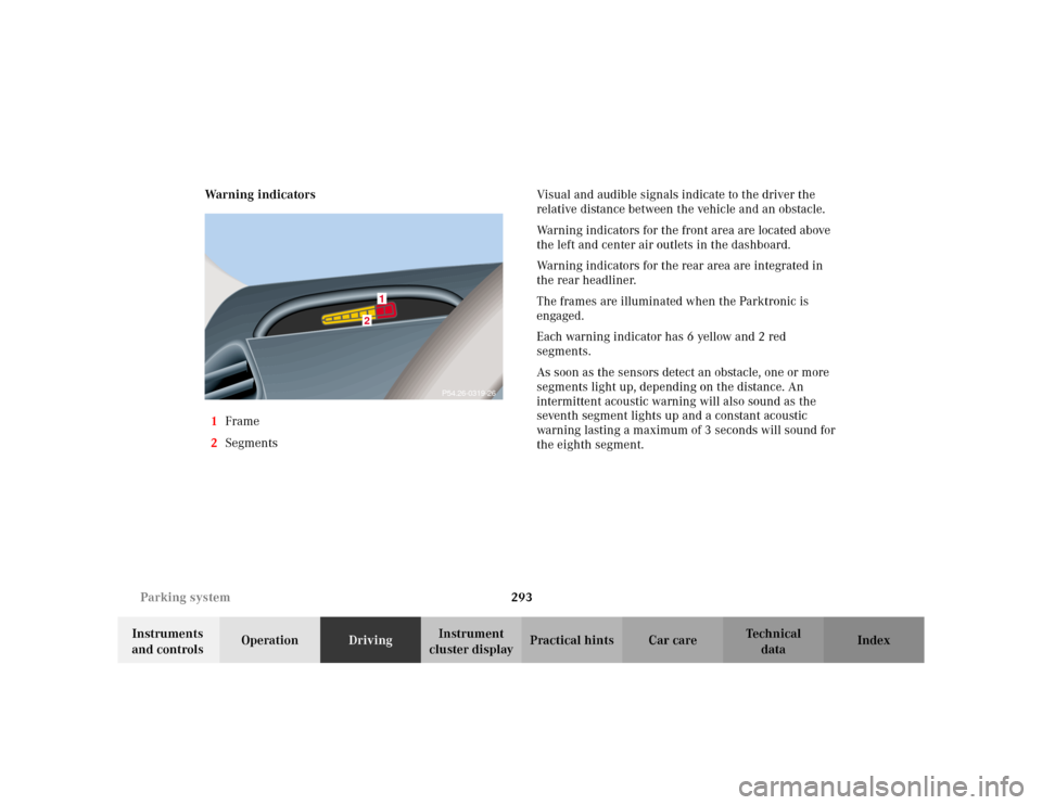
cluster displayPractical hints Car care Index Warning indicators
1Frame
2SegmentsVisual and audible signals indicate to the driver the
relative distance between the vehicle and an obstacle.
Warning indicators for the front area are located above
the left and center air outlets in the dashboard.
Warning indicators for the rear area are integrated in
the rear headliner.
The frames are illuminated when the Parktronic is
engaged.
Each warning indicator has 6 yellow and 2 red
segments.
As soon as the sensors detect an obstacle, one or more
segments light up, depending on the distance. An
intermittent acoustic warning will also sound as the
seventh segment lights up and a constant acoustic
warning lasting a maximum of 3 seconds will sound for
the eighth segment.
2
1
P54.26-0319-26
Page 297 of 430
294 Parking system
Te ch n i c a l
data Instruments
and controlsOperationDrivingInstrument
cluster displayPractical hints Car care Index
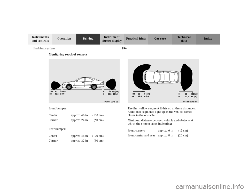
Monitoring reach of sensors
Front bumper:
Rear bumper:The first yellow segment lights up at these distances.
Additional segments light up as the vehicle comes
closer to the obstacle.
Minimum distance between vehicle and obstacle at
which the system stops indicating: Center approx. 40 in (100 cm)
Corner approx. 24 in (60 cm)
Center approx. 48 in (120 cm)
Corner approx. 32 in (80 cm)
Front corners approx. 6 in (15 cm)
Front center and rear approx. 8 in (20 cm)
Page 298 of 430
295 Parking system
Te ch n i c a l
data Instruments
and controlsOperationDrivingInstrument
cluster displayPractical hints Car care Index The obstacle may not be recognized if outside the
shaded sensor field, and no longer be indicated when
approaching it any closer (warning indicators go out).
Parktronic malfunction
All red segments of the warning indicators light up, and
a warning sounds for 3 seconds, if Parktronic does not
function properly.
A dirty sensor or other ultrasonic signals could be the
reason. See page 386 for instructions on cleaning the
sensors in the bumpers.
After cleaning the sensors, turn electronic key in starter
switch to position 2. If the defect continues to be
displayed, have the system checked at your authorized
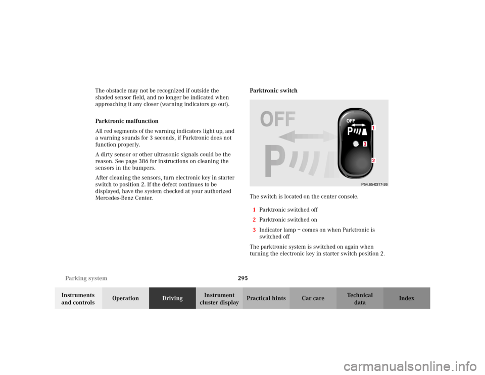
Mercedes-Benz Center.Parktronic switch
The switch is located on the center console.
1Parktronic switched off
2Parktronic switched on
3Indicator lamp – comes on when Parktronic is
switched off
The parktronic system is switched on again when
turning the electronic key in starter switch position 2.3
Page 304 of 430
301 Contents – Instrument cluster display
Te ch n i c a l
data Instruments
and controlsOperation DrivingInstrument
cluster displayPractical hints Car care Index
Instrument cluster displayMalfunction and indicator
lamps in the
instrument cluster ....................302
On-board diagnostic
system ..........................................302
Check engine malfunction
indicator lamp .............................302
Brake warning lamp ..................304
Supplemental restraint system
(SRS) indicator lamp ..................305
Fuel reserve warning .................305
ABS malfunction
indicator lamp .............................306
Electronic stability program
(ESP) — warning lamp ...............307
Distronic (DTR) –
warning lamp ..............................307
Seat belt nonusage
warning lamp ..............................308Malfunction and indicator
lamp in the
center console ........................... 308
AIRBAG OFF indicator lamp .... 308
Malfunction and warning
messages in the
multifunction display .............. 309
DISPLAY DEFECTIVE ................. 310
BATTERY/ALTERNATOR ........... 311
ENTRANCE POSITION ...............312
BRAKE ASSIST ............................312
BRAKE LINING WEAR ............... 313
BRAKE FLUID ............................. 313
PARKING BRAKE ........................ 314
TRUNK OPEN .............................. 314
ELEC. STABIL. PROG.
(Electronic stability
program) ...................................... 315
COOLANT
(coolant level) .............................. 316
COOLANT
(coolant temperature) ................ 317LIGHTING SYSTEM .................... 318
LIGHT SENSOR ...........................320
ACTIVE BODY CONTROL
(ABC) ............................................320
TIRE PRESSURE .........................322
ENGINE OIL LEVEL ...................324
CRUISE CONTROL .....................325
KEY ...............................................325
DOOR ...........................................326
HOOD ...........................................326
TELE AID .....................................327
CHIP-CARD
(KEYLESS-GO) ............................328
SELECTOR LEVER ......................329
TELEPHONE – FUNCTION .......329
WASHER FLUID .........................330
AIR SPRING (AirMatic) ............. 331
DISTRONIC (DTR) ......................332
AIR CLEANER .............................333
Page 323 of 430
320 Malfunction and warning messages
Te ch n i c a l
data Instruments
and controlsOperation DrivingInstrument
cluster displayPractical hints Car care Index
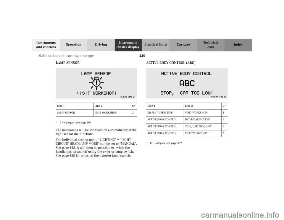
LAMP SENSOR
* C = Category, see page 309The headlamps will be switched on automatically if the
light sensor malfunctions.
The individual setting menu “LIGHTING” – “LIGHT
CIRCUIT HEADLAMP MODE” can be set to “MANUAL”.
See page 142. It will then be possible to switch the
headlamps on and off using the exterior lamp switch.
See page 158 for notes on the exterior lamp switch. ACTIVE BODY CONTROL (ABC)
* C = Category, see page 309 Line 1 Line 2 C*
LAMP SENSOR VISIT WORKSHOP! 2Line 1 Line 2 C*
DISPLAY DEFECTIVE VISIT WORKSHOP!
1
2
ACTIVE BODY CONTROL DRIVE CAREFULLY!
2
1
ACTIVE BODY CONTROL STOP, CAR TOO LOW!
3
1
ACTIVE BODY CONTROL VISIT WORKSHOP!
4
2
Page 326 of 430
323 Malfunction and warning messages
Te ch n i c a l
data Instruments
and controlsOperation DrivingInstrument
cluster displayPractical hints Car care Index
1 One or more tires is or has deflated rapidly. Carefully bring the
vehicle to a halt, avoiding abrupt steering and braking maneuvers.
For reference on changing wheels, see page 348.
2 The tire pressure on one or more tires is already below minimum
value. Carefully bring the vehicle to a halt, avoiding abrupt
steering and braking maneuvers. For reference on changing
wheels, see page 351.
3 For tire inflation pressure monitor, see page 152.4 Tire pressure in one or more tires is low. Check and correct tire
pressure according to the label affixed inside the fuel filler flap.
For tire inflation pressure, see page 356.
The tire inf lation pressure monitor must be activated again after
the tire inflation pressure has been corrected, see page 152.
5 When the message appears after starting the engine, the tire
inflation pressure on all road wheels should be checked and
corrected according to the label affixed inside the fuel filler flap.
For tire inflation pressure, see page 356.
The tire inf lation pressure monitor must be activated again after
the tire inflation pressure has been corrected, see page 152.
6 The tire inflation pressure monitor system is unable to monitor the
tire pressure due to the presence of several wheel electronics in
the vehicle (e.g. a deflated road wheel in the trunk), or nearby
radio interference source, or excessive wheel sensor temperatures,
or unrecognized wheel sensors mounted.
7 The tire inflation pressure monitor is defective or a wheel without
proper sensor was installed. Visit your authorized Mercedes-Benz
Center.Wa r n i n g !
Do not drive with a flat tire. A flat tire affects the
ability to steer or brake the vehicle. You may lose
control of the vehicle. Continued driving with a flat
tire will cause excessive heat build-up and possibly
a fire.