lock MERCEDES-BENZ SL-Class 2015 R131 Owner's Manual
[x] Cancel search | Manufacturer: MERCEDES-BENZ, Model Year: 2015, Model line: SL-Class, Model: MERCEDES-BENZ SL-Class 2015 R131Pages: 610, PDF Size: 12.21 MB
Page 530 of 610
When programing a garage door opener, park
the vehicle outside the garage. Do not run the
engine while programing.
Certain garage door drives are incompatible
with the integrated garage door opener. If you have difficulty programing the integrated
garage door opener, contact an authorized
Mercedes-Benz Center.
Alternatively, you can call the following tele-
phone assistance services:
R USA: Mercedes-Benz Customer Assistance
Center at 1-800-FOR-MERCedes
R Canada: Customer Service at
1-800-387-0100
R HomeLink ®
hotline 1-800-355-3515 (free
of charge)
More information on HomeLink ®
and/or
compatible products is also available online
at http://www.homelink.com.
Notes on the declaration of conformity
(Y page 34).
USA: FCC ID: CB2HMIHL4
Canada: IC: 279B-HMIHL4
Important safety notes G
WARNING
When you operate or program the garage door with the integrated garage door opener, per-
sons in the range of movement of the garage
door can become trapped or struck by the
garage door. There is a risk of injury.
When using the integrated garage door
opener, always make sure that nobody is
within the range of movement of the garage
door. G
WARNING
Combustion engines emit poisonous exhaust
gases such as carbon monoxide. Inhaling
these exhaust gases leads to poisoning. There is a risk of fatal injury. Therefore never leave
the engine running in enclosed spaces with-
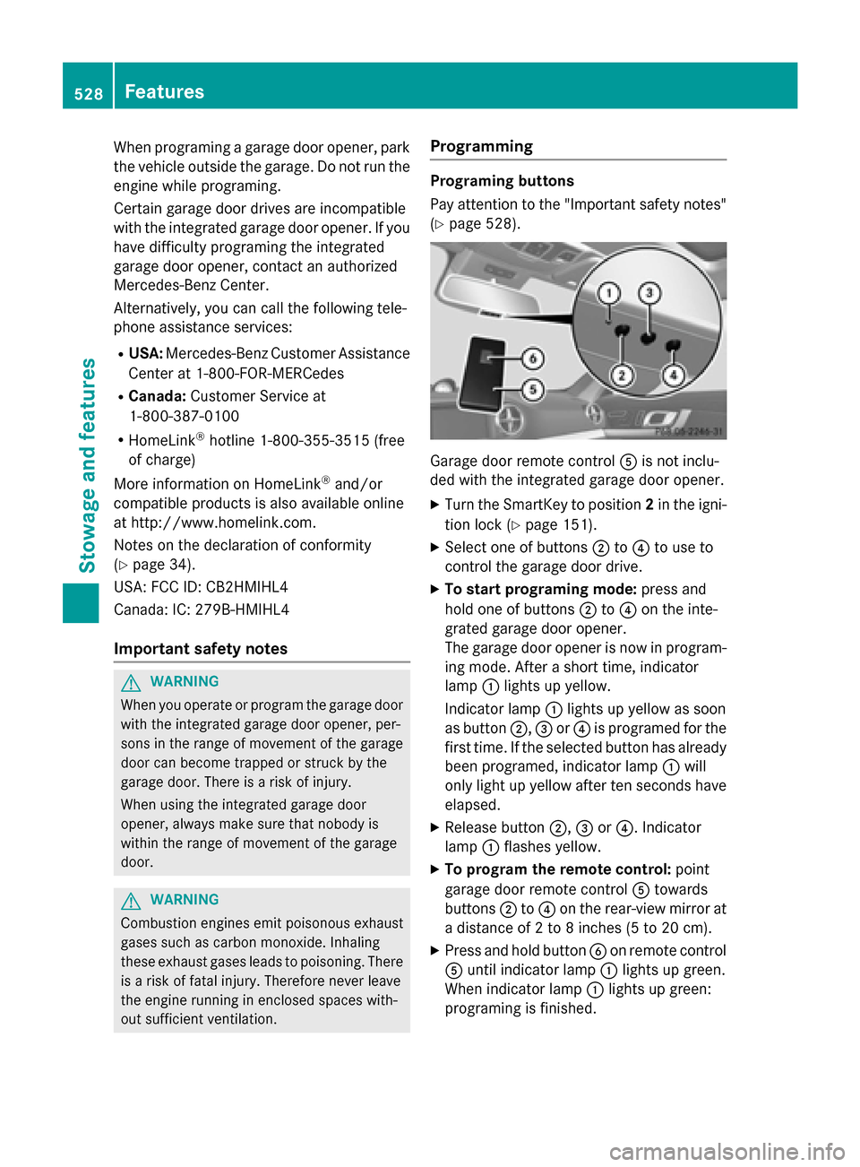
out sufficient ventilation. Programming Programing buttons
Pay attention to the "Important safety notes"
(Y page 528). Garage door remote control
0083is not inclu-
ded with the integrated garage door opener.
X Turn the SmartKey to position 2in the igni-
tion lock (Y page 151).
X Select one of buttons 0044to0085 to use to
control the garage door drive.
X To start programing mode: press and
hold one of buttons 0044to0085 on the inte-
grated garage door opener.
The garage door opener is now in program-
ing mode. After a short time, indicator
lamp 0043lights up yellow.
Indicator lamp 0043lights up yellow as soon
as button 0044,0087or0085 is programed for the
first time. If the selected button has already been programed, indicator lamp 0043will
only light up yellow after ten seconds have elapsed.
X Release button 0044,0087or0085. Indicator
lamp 0043flashes yellow.
X To program the remote control: point
garage door remote control 0083towards
buttons 0044to0085 on the rear-view mirror at
a distance of 2 to 8 inches (5 to 20 cm).
X Press and hold button 0084on remote control
0083 until indicator lamp 0043lights up green.
When indicator lamp 0043lights up green:
programing is finished. 528
FeaturesStowage and features
Page 531 of 610
When indicator lamp
0043flashes green: pro-
graming was successful. The next step is to
synchronize the rolling code.
X Release button 0084on remote control 0083for
the garage door drive system.
If indicator lamp 0043lights up red: repeat the
programing procedure for the correspond-
ing button on the rear-view mirror. When
doing so, vary the distance between remote
control 0083and the rear-view mirror.
The required distance between remote
control 0083and the integrated garage door
opener depends on the garage door drive
system. Several attempts might be neces-
sary. You should test every position for at
least 25 seconds before trying another
position.
Synchronizing the rolling code
Pay attention to the "Important safety notes" (Y page 528).
If the garage door system uses a rolling code,
you will also have to synchronize the garage
door system with the integrated garage door
opener in the rear-view mirror. To do this you
will need to use the programing button on the door drive control panel. The programing but-
ton may be positioned at different locations
depending on the manufacturer. It is usually
located on the door drive unit on the garage
ceiling.
Familiarize yourself with the garage door
drive operating instructions, e.g. under "Pro-
graming of additional remote controls",
before carrying out the following steps.
Your vehicle must be within reach of the
garage door or gate opener drive. Make sure
that neither your vehicle nor any persons/
objects are present within the sweep of the
door or gate.
X Turn the SmartKey to position 2in the igni-
tion lock (Y page 151).
X Get out of the vehicle.
X Press the programing button on the door
drive unit. Usually, you now have 30 seconds to ini-
tiate the next step.
X Get into the vehicle.
X Press previously programed button 0044,0087
or 0085 on the integrated garage door opener
until the door closes.
The rolling code synchronization is then
complete.
Notes on programing the remote control
Canadian radio frequency laws require a
"break" (or interruption) of the transmission
signals after broadcasting for a few seconds.
Therefore, these signals may not last long
enough for the integrated garage door
opener. The signal is not recognized during
programing. Comparable with Canadian law,
some U.S. garage door openers also feature a
"break".
Proceed as follows:
R if you live in Canada
R if you have difficulties programing the
garage door opener (regardless of where
you live) when using the programing steps.
X Press and hold one of buttons 0044to0085 on
the integrated garage door opener.
After a short time, indicator lamp 0043lights
up yellow.
X Release the button.
Indicator lamp 0043flashes yellow.
X Press button 0084of garage door remote
control 0083for two seconds, then release it
for two seconds.
X Press button 0084again for two seconds.
X Repeat this sequence on button 0084of
remote control 0083until indicator lamp 0043
lights up green.
When indicator lamp 0043lights up green:
programing is finished. Features
529Stowage and features Z
Page 532 of 610
When indicator lamp
0043flashes green: pro-
graming was successful. The next step is to
synchronize the rolling code.
X Release button 0084of remote control 0083of
the garage door drive.
If indicator lamp 0043lights up red: repeat the
programing process for the corresponding
button on the rear-view mirror. When doing
so, vary the distance between remote con- trol 0083and the rear-view mirror.
The required distance between remote
control 0083and the integrated garage door
opener depends on the garage door drive
system. Several attempts might be neces-
sary. You should test every position for at
least 25 seconds before trying another
position.
Problems when programing
If you are experiencing problems programing
the integrated garage door opener on the
rear-view mirror, take note of the following
instructions:
R Check the transmitter frequency used by
garage door drive remote control 0083and
whether it is supported. The transmitter
frequency can usually be found on the back
of the garage door drive remote control.
The integrated garage door opener is com-
patible with devices that have units which
operate in the frequency range of 280 to
433 MHz.
R Replace the batteries in garage door
remote control 0083. This increases the like-
lihood that garage door remote control 0083
will transmit a strong and precise signal to the integrated garage door opener.
R When programing, hold remote control 0083
at varying distances and angles from the
button which you are programing. Try vari-
ous angles at a distance between 2and
12 inches (5to 30 cm) or at the same angle
but at varying distances.
R If another remote control is available for the
same garage door drive, repeat the same
programing steps with this remote control. Before performing these steps, make sure
that new batteries have been installed in
garage door drive remote control
0083.
R Note that some remote controls only trans-
mit for a limited amount of time (the indi-
cator lamp on the remote control goes out).
Press button 0084on remote control 0083again
before transmission ends.
R Align the antenna cable of the garage door
opener unit. This can improve signal recep-tion/transmission.
Opening/closing the garage door After it has been programed, the integrated
garage door opener performs the function of
the garage door system remote control.
Please also read the operating instructions
for the garage door system.
X Turn the SmartKey to position 2in the igni-
tion lock (Y page 151).
X Press button 0044,0087or0085 which you have
programed to operate the garage door.
Garage door system with a fixed code: indi-
cator lamp 0043lights up green.
Garage door system with a rolling code:
indicator lamp 0043flashes green.
The transmitter will transmit a signal as long
as the button is pressed. The transmission is halted after a maximum of ten seconds and
indicator lamp 0043lights up yellow. Press but-
ton 0044, 0087or0085 again if necessary.
Clearing the memory Make sure that you clear the memory of the
integrated garage door opener before selling
the vehicle.
X Turn the SmartKey to position 2in the igni-
tion lock (Y page 151).
X Press and hold buttons 0044and 0085.
The indicator lamp initially lights up yellow
and then green.
X Release buttons 0044and 0085.
The memory of the integrated garage door
opener in the rear-view mirror is cleared. 530
FeaturesStowage and features
Page 536 of 610
Useful information
i This Operator's manual describes all
models and all standard and optional equip- ment of your vehicle available at the time of
publication of the Operator's manual.
Country-specific differences are possible.
Please note that your vehicle may not be
equipped with all features described. This
also applies to safety-related systems and
functions.
i Read the information on qualified special-
ist workshops (Y page 35). Engine compartment
Hood
Important safety notes G
WARNING
If the hood is unlatched, it may open up when the vehicle is in motion and block your view.
There is a risk of an accident.
Never unlatch the hood while driving. G
WARNING
When opening and closing the hood, it may
suddenly fall into the closed position. There is a risk of injury to persons within range of
movement of the hood.
Open and close the hood only when no one is
within its range of movement. G
WARNING
Opening the hood when the engine is over-
heated or when there is a fire in the engine
compartment could expose you to hot gases
or other service products. There is a risk of
injury.
Let an overheated engine cool down before
opening the hood. If there is a fire in the
engine compartment, keep the hood closed
and contact the fire department. G
WARNING
The engine compartment contains moving
components. Certain components, such as
the radiator fan, may continue to run or start
again suddenly when the ignition is off. There is a risk of injury.
If you need to do any work inside the engine
compartment:
R switch off the ignition
R never reach into the area where there is a
risk of danger from moving components,
such as the fan rotation area
R remove jewelry and watches
R keep items of clothing and hair, for exam-
ple, away from moving parts
Opening the hood G
WARNING
Certain components in the engine compart-
ment, such as the engine, radiator and parts
of the exhaust system, can become very hot.
Working in the engine compartment poses a
risk of injury.
Where possible, let the engine cool down and touch only the components described in the
following. G
WARNING
When the hood is open and the windshield
wipers are set in motion, you can be injured by the wiper linkage. There is a risk of injury.
Always switch off the windshield wipers and
the ignition before opening the hood.
! Make sure that the windshield wipers are
not folded away from the windshield. You
could otherwise damage the windshield
wipers or the hood. 534
Engine compartmentMaintenance and care
Page 538 of 610
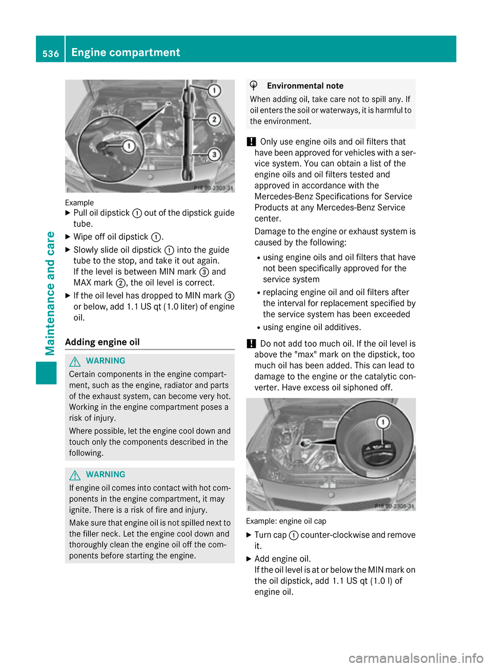
Example
X Pull oil dipstick 0043out of the dipstick guide
tube.
X Wipe off oil dipstick 0043.
X Slowly slide oil dipstick 0043into the guide
tube to the stop, and take it out again.
If the level is between MIN mark 0087and
MAX mark 0044, the oil level is correct.
X If the oil level has dropped to MIN mark 0087
or below, add 1.1 US qt (1.0 liter) of engine oil.
Adding engine oil G
WARNING
Certain components in the engine compart-
ment, such as the engine, radiator and parts
of the exhaust system, can become very hot.
Working in the engine compartment poses a
risk of injury.
Where possible, let the engine cool down and touch only the components described in the
following. G
WARNING
If engine oil comes into contact with hot com- ponents in the engine compartment, it may
ignite. There is a risk of fire and injury.
Make sure that engine oil is not spilled next to
the filler neck. Let the engine cool down and
thoroughly clean the engine oil off the com-
ponents before starting the engine. H
Environmental note
When adding oil, take care not to spill any. If
oil enters the soil or waterways, it is harmful to the environment.
! Only use engine oils and oil filters that
have been approved for vehicles with a ser-
vice system. You can obtain a list of the
engine oils and oil filters tested and
approved in accordance with the
Mercedes-Benz Specifications for Service
Products at any Mercedes-Benz Service
center.
Damage to the engine or exhaust system is caused by the following:
R using engine oils and oil filters that have
not been specifically approved for the
service system
R replacing engine oil and oil filters after
the interval for replacement specified by
the service system has been exceeded
R using engine oil additives.
! Do not add too much oil. If the oil level is
above the "max" mark on the dipstick, too
much oil has been added. This can lead to
damage to the engine or the catalytic con-
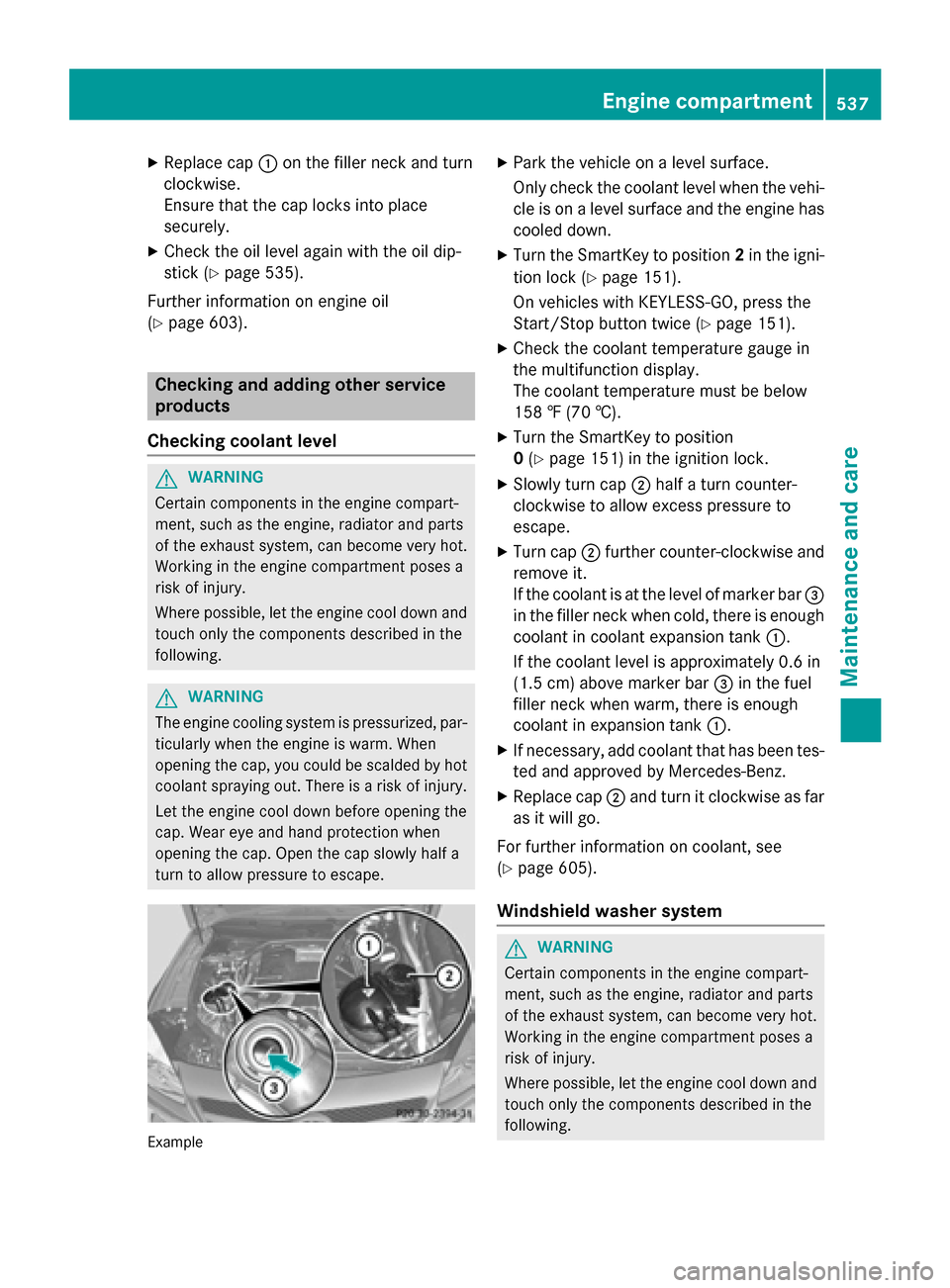
verter. Have excess oil siphoned off. Example: engine oil cap
X Turn cap 0043counter-clockwise and remove
it.
X Add engine oil.
If the oil level is at or below the MIN mark on
the oil dipstick, add 1.1 US qt (1.0 l)of
engine oil. 536
Engine compartmentMaintenance and care
Page 539 of 610
X
Replace cap 0043on the filler neck and turn
clockwise.
Ensure that the cap locks into place
securely.
X Check the oil level again with the oil dip-
stick (Y page 535).
Further information on engine oil
(Y page 603). Checking and adding other service
products
Checking coolant level G
WARNING
Certain components in the engine compart-
ment, such as the engine, radiator and parts
of the exhaust system, can become very hot.
Working in the engine compartment poses a
risk of injury.
Where possible, let the engine cool down and touch only the components described in the
following. G
WARNING
The engine cooling system is pressurized, par- ticularly when the engine is warm. When
opening the cap, you could be scalded by hotcoolant spraying out. There is a risk of injury.
Let the engine cool down before opening the
cap. Wear eye and hand protection when
opening the cap. Open the cap slowly half a
turn to allow pressure to escape. Example X
Park the vehicle on a level surface.
Only check the coolant level when the vehi- cle is on a level surface and the engine has
cooled down.
X Turn the SmartKey to position 2in the igni-
tion lock (Y page 151).
On vehicles with KEYLESS-GO, press the
Start/Stop button twice (Y page 151).
X Check the coolant temperature gauge in
the multifunction display.
The coolant temperature must be below
158 ‡ (70 †).
X Turn the SmartKey to position
0(Y page 151) in the ignition lock.
X Slowly turn cap 0044half a turn counter-
clockwise to allow excess pressure to
escape.
X Turn cap 0044further counter-clockwise and
remove it.
If the coolant is at the level of marker bar 0087
in the filler neck when cold, there is enough coolant in coolant expansion tank 0043.
If the coolant level is approximately 0.6 in
(1.5 cm) above marker bar 0087in the fuel
filler neck when warm, there is enough
coolant in expansion tank 0043.
X If necessary, add coolant that has been tes-
ted and approved by Mercedes-Benz.
X Replace cap 0044and turn it clockwise as far
as it will go.
For further information on coolant, see
(Y page 605).
Windshield washer system G
WARNING
Certain components in the engine compart-
ment, such as the engine, radiator and parts
of the exhaust system, can become very hot.
Working in the engine compartment poses a
risk of injury.
Where possible, let the engine cool down and touch only the components described in the
following. Engine compartment
537Maintenance and care Z
Page 550 of 610
Useful information
i This Operator's manual describes all
models and all standard and optional equip- ment of your vehicle available at the time of
publication of the Operator's manual.
Country-specific differences are possible.
Please note that your vehicle may not be
equipped with all features described. This
also applies to safety-related systems and
functions.
i Read the information on qualified special-
ist workshops (Y page 35). Where will I find...?
Vehicle tool kit
General notes The vehicle tool kit consists of a towing eye
and test gauge for measuring the brake pad
thickness (Y page 178). The towing eye is
located in the trunk in a bracket below the
trunk lid lock. The gauge for measuring brake
pad/lining thickness is in the vehicle docu-
ment wallet. If the vehicle is equipped with a
TIREFIT kit, it is located in the stowage com-
partment under the trunk floor. MOE as
standard, optional equipment - standard tires with TIREFIT. -->
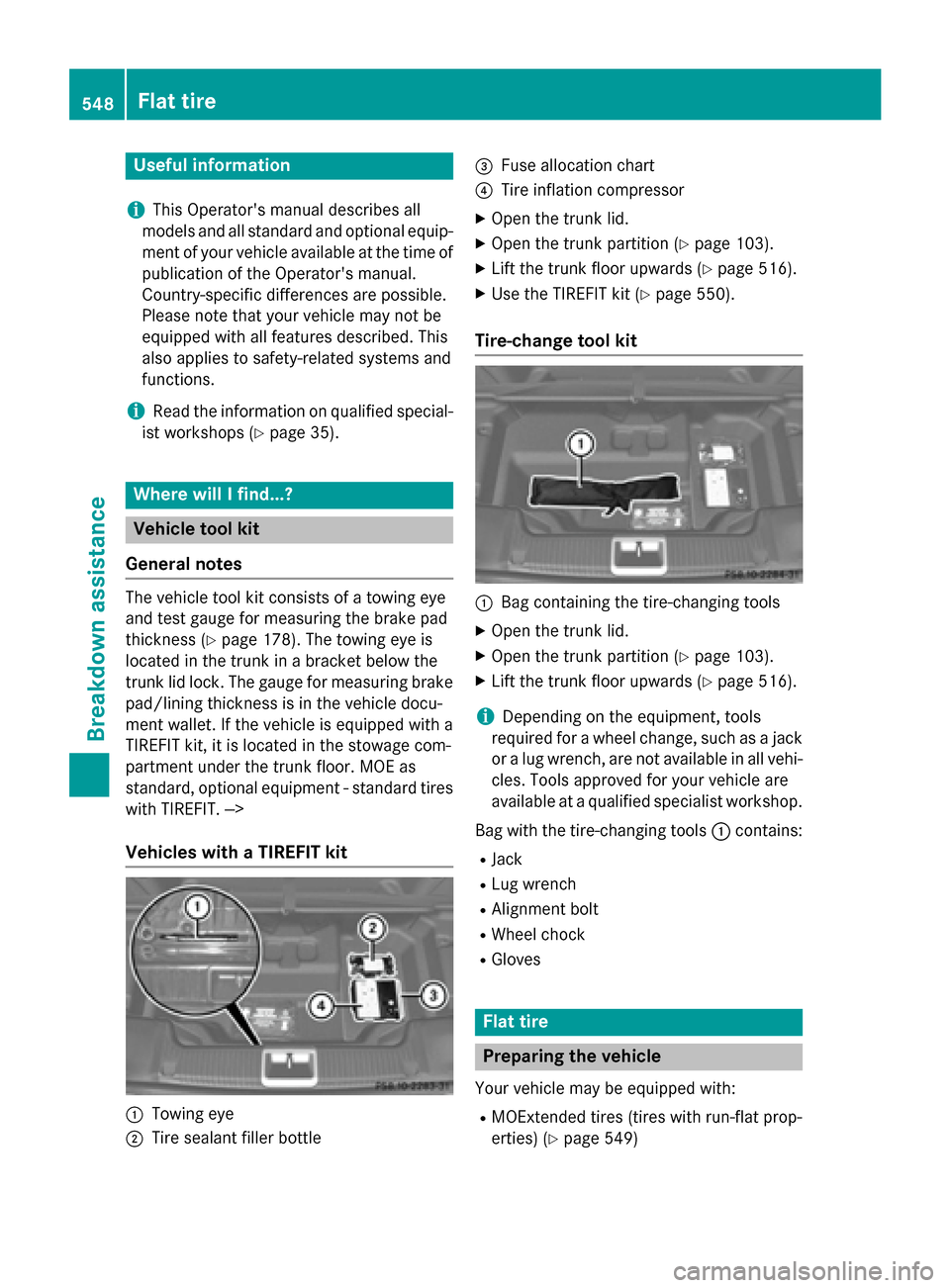
Vehicles with a TIREFIT kit 0043
Towing eye
0044 Tire sealant filler bottle 0087
Fuse allocation chart
0085 Tire inflation compressor
X Open the trunk lid.
X Open the trunk partition (Y page 103).
X Lift the trunk floor upwards (Y page 516).
X Use the TIREFIT kit (Y page 550).
Tire-change tool kit 0043
Bag containing the tire-changing tools
X Open the trunk lid.
X Open the trunk partition (Y page 103).
X Lift the trunk floor upwards (Y page 516).
i Depending on the equipment, tools
required for a wheel change, such as a jack or a lug wrench, are not available in all vehi-
cles. Tools approved for your vehicle are
available at a qualified specialist workshop.
Bag with the tire-changing tools 0043contains:
R Jack
R Lug wrench
R Alignment bolt
R Wheel chock
R Gloves Flat tire
Preparing the vehicle
Your vehicle may be equipped with: R MOExtended tires (tires with run-flat prop-
erties) (Y page 549) 548
Flat tireBreakdown assistance
Page 551 of 610
Vehicle preparation is not necessary on
vehicles with MOExtended tires
R a TIREFIT kit (Y page 548)
Information on changing/mounting a wheel
(Y page 588).
X Stop the vehicle on solid, non-slippery and
level ground, as far away as possible from
traffic.
X Switch on the hazard warning lamps.
X Secure the vehicle against rolling away
(Y page 171).
X If possible, bring the front wheels into the
straight-ahead position.
X Switch off the engine.
X Vehicles without KEYLESS-GO: remove
the SmartKey from the ignition lock.
X Vehicles with KEYLESS-GO: open the
driver's door.
The on-board electronics now have status
0. This is the same as the SmartKey having
been removed.
X Vehicles with KEYLESS-GO: remove the
Start/Stop button from the ignition lock
(Y page 151).
X All occupants must get out of the vehicle.
Make sure that they are not endangered as
they do so.
X Make sure that no one is near the danger
area while a wheel is being changed. Any-
one who is not directly assisting in the
wheel change should, for example, stand
behind the barrier.
X Get out of the vehicle. Pay attention to traf-
fic conditions when doing so.
X Close the driver's door. MOExtended tires (tires with run-flat
properties)
General notes With MOExtended tires (tires with run flat
characteristics), you can continue to drive
your vehicle even if there is a total loss of pressure in one or more tires. The affected
tire must not show any clearly visible damage.
You can recognize MOExtended tires by the
MOExtended marking which appears on the
sidewall of the tire. You will find this marking next to the tire size designation, the load-
bearing capacity and the speed index
(Y page 582).
MOExtended tires may only be used in con-
junction with an active tire pressure monitor.
If the pressure loss warning message
appears in the multifunction display:
R Observe the instructions in the display
messages (Y page 263).
R Check the tire for damage.
R If driving on, observe the following notes.
The maximum driving distance is approx-
imately 50 miles (80 km) when the vehicle is
partially laden and approximately 18 miles
(30 km) when the vehicle is fully laden.
In addition to the vehicle load, the driving dis- tance possible depends upon:
R Speed
R Road condition
R Outside temperature
The driving distance possible in run-flat mode may be reduced by extreme driving condi-
tions/maneuvers, or it can be increased
through a moderate style of driving.
The maximum permissible distance which
can be driven in run-flat mode is counted from
the moment the tire pressure loss warning
appears in the multifunction display.
You must not exceed a maximum speed of
50 mph (80 km/h).
i When replacing one or all tires, make sure
that you use only tires:
R of the size specified for the vehicle and
R marked "MOExtended"
If a tire has gone flat and cannot be
replaced with a MOExtended tire, a stand-
ard tire may be used as a temporary meas-
ure. Make sure that you use the proper size and type (summer or winter tire). Flat tire
549Breakdown assistance
Page 553 of 610
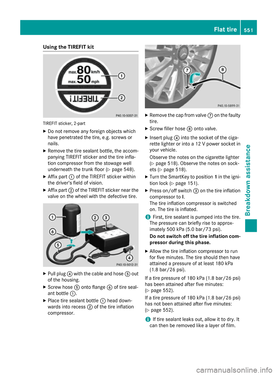
Using the TIREFIT kit
TIREFIT sticker, 2-part
X Do not remove any foreign objects which
have penetrated the tire, e.g. screws or
nails.
X Remove the tire sealant bottle, the accom-
panying TIREFIT sticker and the tire infla-
tion compressor from the stowage well
underneath the trunk floor (Y page 548).
X Affix part 0043of the TIREFIT sticker within
the driver's field of vision.
X Affix part 0044of the TIREFIT sticker near the
valve on the wheel with the defective tire. X
Pull plug 0085with the cable and hose 0083out
of the housing.
X Screw hose 0083onto flange 0084of tire seal-
ant bottle 0043.
X Place tire sealant bottle 0043head down-
wards into recess 0044of the tire inflation
compressor. X
Remove the cap from valve 006Bon the faulty
tire.
X Screw filler hose 006Conto valve.
X Insert plug 0085into the socket of the ciga-
rette lighter or into a 12 V power socket in
your vehicle.
Observe the notes on the cigarette lighter
(Y page 518). Observe the notes on sock-
ets (Y page 518).
X Turn the SmartKey to position 1in the igni-
tion lock (Y page 151).
X Press on/off switch 0087on the tire inflation
compressor to I.
The tire inflation compressor is switched
on. The tire is inflated.
i First, tire sealant is pumped into the tire.
The pressure can briefly rise to approx-
imately 500 kPa (5.0 bar/73 psi).
Do not switch off the tire inflation com-
pressor during this phase.
X Allow the tire inflation compressor to run
for five minutes. The tire should then have
attained a pressure of at least 180 kPa
(1.8 bar/26 psi).
If a tire pressure of 180 kPa (1.8 bar/26 psi) has been attained after five minutes:
(Y page 552).
If a tire pressure of 180 kPa (1.8 bar/26 psi) has not been attained after five minutes:
(Y page 552).
i If tire sealant leaks out, allow it to dry. It
can then be removed like a layer of film. Flat tire
551Breakdown assistance Z
Page 555 of 610
ard on the driver's side B-pillar or tire pres-
sure table on the fuel filler flap).
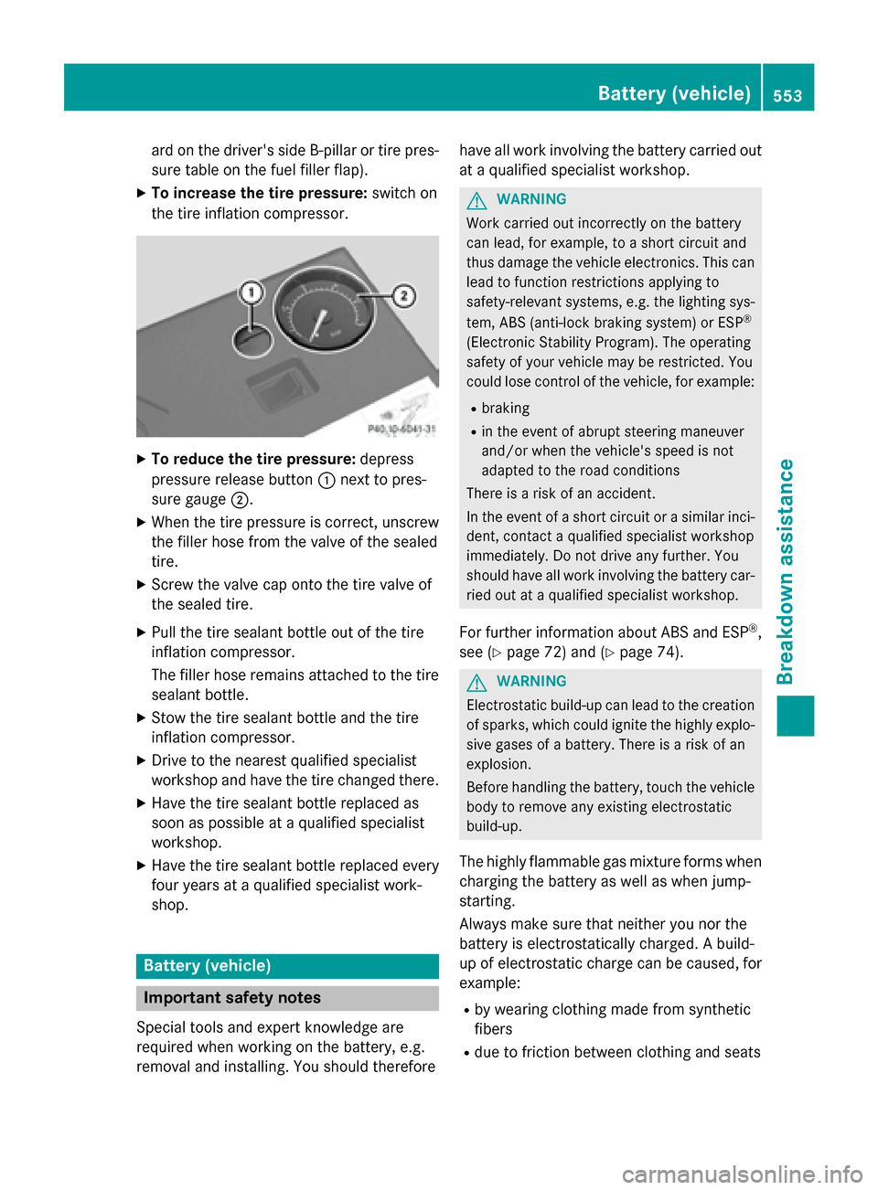
X To increase the tire pressure: switch on
the tire inflation compressor. X
To reduce the tire pressure: depress
pressure release button 0043next to pres-
sure gauge 0044.
X When the tire pressure is correct, unscrew
the filler hose from the valve of the sealed
tire.
X Screw the valve cap onto the tire valve of
the sealed tire.
X Pull the tire sealant bottle out of the tire
inflation compressor.
The filler hose remains attached to the tire
sealant bottle.
X Stow the tire sealant bottle and the tire
inflation compressor.
X Drive to the nearest qualified specialist
workshop and have the tire changed there.
X Have the tire sealant bottle replaced as
soon as possible at a qualified specialist
workshop.
X Have the tire sealant bottle replaced every
four years at a qualified specialist work-
shop. Battery (vehicle)
Important safety notes
Special tools and expert knowledge are
required when working on the battery, e.g.
removal and installing. You should therefore have all work involving the battery carried out
at a qualified specialist workshop. G
WARNING
Work carried out incorrectly on the battery
can lead, for example, to a short circuit and
thus damage the vehicle electronics. This can lead to function restrictions applying to
safety-relevant systems, e.g. the lighting sys-
tem, ABS (anti-lock braking system) or ESP ®
(Electronic Stability Program). The operating
safety of your vehicle may be restricted. You
could lose control of the vehicle, for example:
R braking
R in the event of abrupt steering maneuver
and/or when the vehicle's speed is not
adapted to the road conditions
There is a risk of an accident.
In the event of a short circuit or a similar inci- dent, contact a qualified specialist workshop
immediately. Do not drive any further. You
should have all work involving the battery car-
ried out at a qualified specialist workshop.
For further information about ABS and ESP ®
,
see (Y page 72) and (Y page 74). G
WARNING
Electrostatic build-up can lead to the creation of sparks, which could ignite the highly explo-
sive gases of a battery. There is a risk of an
explosion.
Before handling the battery, touch the vehicle body to remove any existing electrostatic
build-up.
The highly flammable gas mixture forms when
charging the battery as well as when jump-
starting.
Always make sure that neither you nor the
battery is electrostatically charged. A build-
up of electrostatic charge can be caused, for
example:
R by wearing clothing made from synthetic
fibers
R due to friction between clothing and seats Battery (vehicle)
553Breakdown assistance Z