allocation MERCEDES-BENZ SL-Class 2016 R231 Owner's Manual
[x] Cancel search | Manufacturer: MERCEDES-BENZ, Model Year: 2016, Model line: SL-Class, Model: MERCEDES-BENZ SL-Class 2016 R231Pages: 614, PDF Size: 15.67 MB
Page 15 of 614

Fuel levelCalling up the range (on-board
computer) ...................................... 226
Fuel tank
Capacity ........................................ 603
Problem (malfunction) .................. .171
Fuse allocation chart (vehicle tool
kit) ...................................................... 550
Fuses
Allocation chart .............................5 64
Before changing .............................5 64
Dashboard fuse box ....................... 565
Fuse box in the engine compart-
ment .............................................. 565
Fuse box in the rear compartment .. 566
Important safety notes .................. 564
G
Garage door opener
Clearing the memory ..................... 533
General notes ................................ 529
Important safety notes .................. 530
Opening/closing the garage door .. 533
Programming (button in the rear-
view mirror) ................................... 530
Synchronizing the rolling code ....... 531
Gear indicator (on-board com-
puter, Mercedes-AMG vehicles) ....... 236
Genuine parts ...................................... 30
Glass roof (sunblind) ......................... 104
Glove box ...........................................5 14
Google™ Local Search
Importing a destination/route ....... 421
Popular Searches ........................... 422
Search ........................................... 420
Search history ............................... 422
Selecting a search position ............ 421
Using as the destination ................ 421
GPS reception .................................... 321
Gracenote
®Media Database ............ 450
H
Handbrake
see Parking brake
HANDS-FREE ACCESS .......................... 93Harman/kardon
®Logic 7®sur-
round sound system
see Surround sound (harman/
kardon
®surround sound system)
Hazard warning lamps
Display message ............................ 269
Switching on/off ........................... 126
Head bags
Display message ............................ 249
Operation ......................................... 58
Head level heating (AIRSCARF) ........ 114
Head restraints
Adjusting ....................................... 111
see NECK-PRO head restraints
Heading up (navigation) ................... 368
Headlamps
Cleaning system (notes) ................ 607
Fogging up ..................................... 128
see Automatic headlamp mode
Headphones
Changing batteries ........................ 487
Heating
see Climate control
High-beam headlamps
Display message ............................ 253
Switching on/off ........................... 125
Highway information ........................ 371
Hill start assist .................................. 154
HOLD function
Activating ....................................... 192
Deactivating ................................... 192
Display message ............................ 259
Function/notes ............................. 191
Home address
Entering and storing ...................... 329
Selecting from the destination
memory ......................................... 330
Hood
Closing ........................................... 537
Display message ............................ 267
Important safety notes .................. 536
Opening ......................................... 536
Horn ...................................................... 40
Hydroplaning ..................................... 179
Index13
Page 552 of 614

Useful information
i
This Operator's Manual describes all
models and all standard and optional equip-
ment of your vehicle available at the time of
publication of the Operator's Manual.
Country-specific differences are possible.
Please note that your vehicle may not be
equipped with all features described. This
also applies to safety-related systems and
functions.
iRead the information on qualified special-
ist workshops (
Ypage 34).
Where will I find...?
Vehicle tool kit
General notes
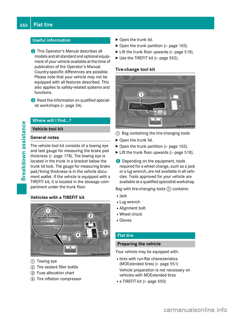
The vehicle tool kit consists of a towing eye
and test gauge for measuring the brake pad
thickness (
Ypage 178). The towing eye is
located in the trunk in a bracket below the
trunk lid lock. The gauge for measuring brake
pad/lining thickness is in the vehicle docu-
ment wallet. If the vehicle is equipped with a
TIREFIT kit, it is located in the stowage com-
partment under the trunk floor.
Vehicles with a TIREFIT kit
:Towing eye
;Tire sealant filler bottle
=Fuse allocation chart
?Tire inflation compressor
XOpen the trunk lid.
XOpen the trunk partition (Ypage 103).
XLift the trunk floor upwards (Ypage 518).
XUse the TIREFIT kit (Ypage 552).
Tire-change tool kit
:Bag containing the tire-changing tools
XOpen the trunk lid.
XOpen the trunk partition (Ypage 103).
XLift the trunk floor upwards (Ypage 518).
iDepending on the equipment, tools
required for a wheel change, such as a jack or a lug wrench, are not available in all vehi-
cles. Tools approved for your vehicle are
available at a qualified specialist workshop.
Bag with tire-changing tools :contains:
RJack
RLug wrench
RAlignment bolt
RWheel chock
RGloves
Flat tire
Preparing the vehicle
Your vehicle may be equipped with:
Rtires with run-flat characteristics
(MOExtended tires) (
Ypage 551)
Vehicle preparation is not necessary on
vehicles with MOExtended tires
Ra TIREFIT kit (Ypage 550)
550Flat tire
Breakdown assistance
Page 566 of 614

The vehicle/trailer combination may oth-
erwise swerve or even roll over.
Transporting the vehicle
!
You may only secure the vehicle by the
wheels, not by parts of the vehicle such as axle or steering components. Otherwise,
the vehicle could be damaged.
The towing eye can be used to pull the vehicle
onto a trailer or transporter for transporting
purposes.
XTurn the SmartKey to position 2in the igni-
tion lock.
XShift the transmission to position N.
As soon as the vehicle has been loaded:
XPrevent the vehicle from rolling away by
applying the electric parking brake.
XShift the transmission to position P.
XTurn the SmartKey to position0in the igni-
tion lock and remove it.
XSecure the vehicle.
Tow-starting (emergency engine
starting)
!
Vehicles with automatic transmission
must not be tow-started. You could other-
wise damage the automatic transmission.
You can find information on "Jump-starting" at
(
Ypage 559).
Fuses
Important safety notes
GWARNING
If you manipulate or bridge a faulty fuse or if
you replace it with a fuse with a higher amper- age, the electric cables could be overloaded.
This could result in a fire. There is a risk of an
accident and injury.
Always replace faulty fuses with the specifiednew fuses having the correct amperage.
!Only use fuses that have been approved
for Mercedes-Benz vehicles and which
have the correct fuse rating for the system
concerned. Otherwise, components or sys-
tems could be damaged.
The fuses in your vehicle serve to close down
faulty circuits. If a fuse blows, all the compo-
nents on the circuit and their functions stop
operating.
Blown fuses must be replaced with fuses of
the same rating, which you can recognize by
the color and value. The fuse ratings are listed
in the fuse allocation chart.
If a newly inserted fuse also blows, have the
cause traced and rectified at a qualified spe-
cialist workshop, e.g. an authorized
Mercedes-Benz Center.
Before changing a fuse
XSecure the vehicle against rolling away
(
Ypage 171).
XSwitch off all electrical consumers.
XTurn the SmartKey to position 0in the igni-
tion lock and remove it (
Ypage 151).
or
XOn vehicles with KEYLESS-GO, make sure
the ignition is switched off (
Ypage 152).
All indicator lamps in the instrument cluster
must be off.
The fuses are located in various fuse boxes:
RFuse box in the engine compartment on the right-hand side of the vehicle, when viewed
in the direction of travel
RDashboard fuse box
RFuse box in the rear compartment on the
right-hand side of the vehicle, when viewedin the direction of travel
The fuse allocation chart is located in the
vehicle tool kit in the stowage compartment
under the trunk floor (
Ypage 550).
564Fuses
Breakdown assistance
Page 579 of 614

Checking the tire pressure electroni-
cally
XMake sure that the SmartKey is in position2 in the ignition lock (
Ypage 151).
XPress the =or; button on the steer-
ing wheel to select the Serv.
menu.
XPress the9or: button to select
Tire Pressure
.
XPress the abutton.
The current tire pressure of each tire is
shown in the multifunction display.
If the vehicle has been parked for over
20 minutes, the Tire pressure will be
displayed after driving a few
minutesmessage appears.
After a teach-in process, the tire pressure
monitor automatically detects new wheels or
new sensors. As long as a clear allocation of
the tire pressure value to the individual
wheels is not possible, the Tire Pressure
Monitor Activedisplay message is shown
instead of the tire pressure display. The tire
pressures are already being monitored.
Tire pressure monitor warning mes-
sages
If the tire pressure monitor detects a pressure
loss in one or more tires, a warning message
is shown in the multifunction display and the
yellow tire pressure monitor warning lamp
comes on.
RIf the Please Correct Tire Pressure
message appears in the multifunction dis-
play, the tire pressure in at least one tire is
too low and must be corrected at the next
opportunity.
RIf theCheckTiresmessage appears in the
multifunction display, the tire pressure in
one or more tires has dropped significantly
and the tires must be checked.
RIf the Warning Tire Malfunction
appears in the multifunction display, the
tire pressure in one or more tires has drop-
ped suddenly and the tires must be
checked. Observe the instructions and safety notes in
the display messages in the "Tires" section
(
Ypage 264).
iIf the wheel positions on the vehicle are
rotated, the tire pressures may be dis-
played for the wrong positions for a short
time. This is rectified after a few minutes of
driving, and the tire pressures are displayed
for the correct positions.
Restarting the tire pressure monitor
When you restart the tire pressure monitor, all
existing warning messages are deleted and
the warning lamps go out. The monitor uses
the currently set tire pressures as the refer-
ence values for monitoring. In most cases, the
tire pressure monitor will automatically
detect the new reference values after you
have changed the tire pressure. However, you
can also define reference values manually as
described here. The tire pressure monitor
then monitors the new tire pressure values.
XSet the tire pressure to the value recom-
mended for the corresponding driving sit-
uation on the Tire and Loading Information
placard on the driver's side
B-pillar (
Ypage 571).
Additional tire pressure values for different
loads can also be found on the tire pressure
table on the inside of the fuel filler flap
(
Ypage 571).
XMake sure that the tire pressure is correct
on all four wheels.
XMake sure that the SmartKey is in position
2 in the ignition lock.
XPress the =or; button on the steer-
ing wheel to select the Serv.
menu.
XPress the9or: button to select
Tire Pressure
.
XPress the abutton.
The multifunction display shows the cur-
rent tire pressure for the individual tires or
the Tire
pressurewillbedisplayed
Tire pressure577
Wheels and tires
Z