door lock MERCEDES-BENZ SL-CLASS ROADSTER 2014 Owner's Manual
[x] Cancel search | Manufacturer: MERCEDES-BENZ, Model Year: 2014, Model line: SL-CLASS ROADSTER, Model: MERCEDES-BENZ SL-CLASS ROADSTER 2014Pages: 284, PDF Size: 45.52 MB
Page 126 of 284
lock and the SmartKey must be in the
vehicle.
X Depress the brake pedal and keep it
depressed.
X Shift the transmission to position P.
The transmission position display in the
multifunction display shows P.
i You can also start the engine when the
transmission is in position N.
X Press the Start/Stop button once
(Y page 121).
The engine starts. Pulling away
Automatic transmission G
WARNING
If the engine speed is above the idling speed
and you engage transmission position Dor
R, the vehicle could pull away suddenly. There
is a risk of an accident.
When engaging transmission position Dor R,
always firmly depress the brake pedal and do
not simultaneously accelerate.
i It is only possible to shift the transmission
from position Pto the desired position if
you depress the brake pedal. Only then is
the shift lock released.
X Depress the brake pedal and keep it
depressed.
X Shift the transmission to position Dor R.
X Release the electric parking brake, see
Digital Operator's Manual.
X Release the brake pedal.
X Carefully depress the accelerator pedal.
! If a warning tone sounds and the
Release Park. Brake Release Park. Brake message appears
in the multifunction display, the parking
brake is still applied. Release the parking
brake. i
The vehicle locks centrally once you have
pulled away. The locking knobs in the doors
drop down.
You can open the doors from the inside at
any time.
You can also deactivate the automatic
locking feature (Y page 161).
i Upshifts take place at higher engine
speeds after a cold start. This helps the
catalytic converter to reach its operating
temperature more quickly.
Hill start assist Hill start assist helps you when pulling away
forwards or in reverse on an uphill gradient.
It holds the vehicle for a short time after you
have removed your foot from the brake pedal.
This gives you enough time to move your foot
from the brake pedal to the accelerator pedal
and to depress it before the vehicle begins to
roll.
G
WARNING
After a short time, hill start assist will no
longer brake your vehicle and it could roll
away. There is a risk of an accident and injury.
Therefore, quickly move your foot from the
brake pedal to the accelerator pedal. Never
leave the vehicle when it is held by hill start
assist.
X Remove your foot from the brake pedal.
The vehicle is then held for about a second.
X Pull away.
Hill start assist is not active if:
R you are pulling away on a level road or on
a downhill gradient.
R the transmission is in position N.
R the parking brake is applied.
R ESP ®
is malfunctioning. 124
DrivingDriving and parking
Page 131 of 284
X
KEYLESS-GO: open the driver’s door.
This corresponds to key position 0: "key
removed".
The driver’s door can be closed again.
X Press the fuel filler flap in the direction of
arrow :.
Fuel filler flap :swings open.
X Turn the fuel filler flap counter-clockwise
and remove it.
X Insert the fuel filler cap into the holder
bracket on the inside of filler flap ;.
X Completely insert the filler neck of the fuel
pump nozzle into the tank and refuel.
X Only fill the tank until the pump nozzle
switches off.
i Do not add any more fuel after the pump
stops filling for the first time. Otherwise,
fuel could leak out.
Closing the fuel filler flap X
Place fuel filler cap on the fuel filler neck
and turn clockwise until it engages.
X Close the fuel filler flap.
i Close the fuel filler flap before locking the
vehicle.
i If you are driving with the fuel filler cap
open, the 8reserve fuel warning lamp
flashes. The ;Check Engine warning
lamp may also light up. A message appears
in the multifunction display (Y page 163).
For further information on warning and
indicator lamps in the instrument cluster,
see (Y page 175). Refueling
129Driving and parking Z
Page 214 of 284
Alternatively, you can call the following
telephone assistance services:
R USA: Mercedes-Benz Customer
Assistance Center at
1-800-FOR-MERCedes
R Canada: Customer Service at
1-800-387-0100
R HomeLink ®
hotline 1-800-355-3515
(free of charge)
More information on HomeLink ®
and/or
compatible products is also available
online at http://www.homelink.com.
i Notes on the declaration of conformity
(Y page 30).
USA: FCC ID: CB2HMIHL4
Canada: IC: 279B-HMIHL4
Programming Programming buttons
Observe the "Important safety notes"
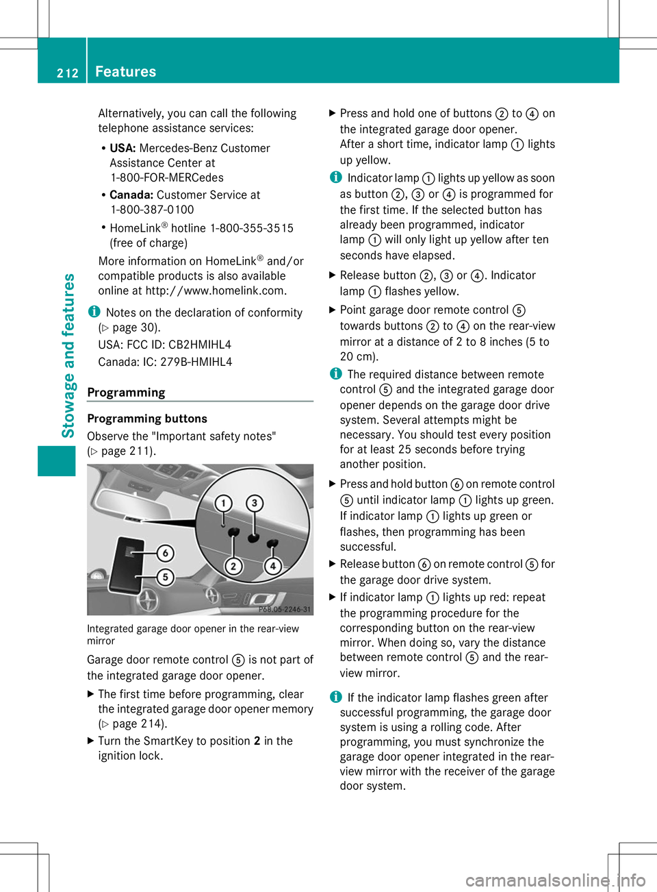
(Y page 211). Integrated garage door opener in the rear-view
mirror
Garage door remote control Ais not part of
the integrated garage door opener.
X The first time before programming, clear
the integrated garage door opener memory
(Y page 214).
X Turn the SmartKey to position 2in the
ignition lock. X
Press and hold one of buttons ;to? on
the integrated garage door opener.
After a short time, indicator lamp :lights
up yellow.
i Indicator lamp :lights up yellow as soon
as button ;,=or? is programmed for
the first time. If the selected button has
already been programmed, indicator
lamp :will only light up yellow after ten
seconds have elapsed.
X Release button ;,=or?. Indicator
lamp :flashes yellow.
X Point garage door remote control A
towards buttons ;to? on the rear-view
mirror at a distance of 2 to 8 inches (5 to
20 cm).
i The required distance between remote
control Aand the integrated garage door
opener depends on the garage door drive
system. Several attempts might be
necessary. You should test every position
for at least 25 seconds before trying
another position.
X Press and hold button Bon remote control
A until indicator lamp :lights up green.
If indicator lamp :lights up green or
flashes, then programming has been
successful.
X Release button Bon remote control Afor
the garage door drive system.
X If indicator lamp :lights up red: repeat
the programming procedure for the
corresponding button on the rear-view
mirror. When doing so, vary the distance
between remote control Aand the rear-
view mirror.
i If the indicator lamp flashes green after
successful programming, the garage door
system is using a rolling code. After
programming, you must synchronize the
garage door opener integrated in the rear-
view mirror with the receiver of the garage
door system. 212
FeaturesSto
wage an d features
Page 215 of 284
Synchronizing the rolling code
Observe the "Important safety notes"
(Y
page 211).
Your vehicle must be within reach of the
garage door or exterior gate drive. Make sure
that neither your vehicle nor any persons/
objects are present within the sweep of the
door or gate.
X Turn the SmartKey to position 2in the
ignition lock.
X Press the program button of the door or
gate drive (see the door or gate drive
operating instructions, e.g. under
"programming of additional remote
controls").
i Usually, you now have 30seconds to
initiate the next step.
X Press previously programmed button ;,
= or? of the integrated garage door
opener until the door closes.
The rolling code synchronization is then
complete.
Notes on programming the remote
control
Canadian radio frequency laws require a
"break" (or interruption) of the transmission
signals after broadcasting for a few seconds.
Therefore, these signals may not last long
enough for the integrated garage door
opener. The signal is not recognized during
programming. Comparable with Canadian
law, some U.S. garage door openers also
feature a "break".
Proceed as follows:
R if you live in Canada
R if you have difficulties programming the
garage door opener (regardless of where
you live) when using the programming
steps X
Press and hold one of buttons ;to? on
the integrated garage door opener.
After a short time, indicator lamp :lights
up yellow.
X Release the button.
Indicator lamp :flashes yellow.
X Press button Bof garage door remote
control Afor two seconds, then release it
for two seconds.
X Press button Bagain for two seconds.
X Repeat this sequence on button Bof
remote control Auntil indicator lamp :
lights up green.
If indicator lamp :turns red, repeat the
process.
X Continue with the other programming
steps (see above).
Problems when programming
If you are experiencing problems
programming the integrated garage door
opener on the rear-view mirror, take note of
the following instructions:
R Check the transmitter frequency of garage
door drive remote control A. This can
usually be found on the back of the remote
control.
The integrated garage door opener is
compatible with devices that have units
which operate in the frequency range of
280to 433MHz.
R Replace the batteries in garage door
remote control A. This increases the
likelihood that garage door remote control
A will transmit a strong and precise signal
to the integrated garage door opener in the
rear-view mirror.
R When programming, hold remote control
A at varying distances and angles from the
button that you are programming. Try
various angles at a distance between 2and
12 inches (5to 30 cm) or at the same angle
but at varying distances.
R If another remote control for the same
garage door drive is available, repeat the Features
213Stowage and features Z
Page 216 of 284
same programming steps with this remote
control. Before performing these steps,
make sure that new batteries have been
installed in garage door drive remote
control A.
R Note that some remote controls only
transmit for a limited amount of time (the
indicator lamp on the remote control goes
out). Press button Bon remote control
A again before transmission ends.
R Align the antenna cable of the garage door
opener unit. This can improve signal
reception/transmission.
Opening/closing the garage door After it has been programmed, the integrated
garage door opener performs the function of
the garage door system remote control.
Please also read the operating instructions
for the garage door system.
X Turn the SmartKey to position 2in the
ignition lock.
X Press button ;,=or? which you have
programmed to operate the garage door.
Garage door system with a fixed code:
indicator lamp :lights up green.
Garage door system with a rolling code:
indicator lamp :flashes green.
i The transmitter will transmit a signal as
long as the button is pressed. The
transmission is halted after a maximum of
ten seconds and indicator lamp :lights
up yellow. Press button ;,=or? again
if necessary.
Clearing the memory X
Turn the SmartKey to position 2in the
ignition lock.
X Press buttons ;and ?.
The indicator lamp lights up yellow.
X Press and hold buttons ;and ?until the
indicator lamp turns green. i
Make sure that you clear the memory of
the integrated garage door opener before
selling the vehicle. Floormats
G
WARNING
Objects in the driver's footwell can restrict the
pedal travel or obstruct a depressed pedal.
The operating and road safety of the vehicle
is jeopardized. There is a risk of an accident.
Make sure that all objects in the vehicle are
stowed correctly, and that they cannot enter
the driver's footwell. Install the floormats
securely and as specified in order to ensure
sufficient clearance for the pedals. Do not use
loose floormats and do not place floormats on
top of one another. X
Slide the seat backwards.
X To install: place the floormat in the
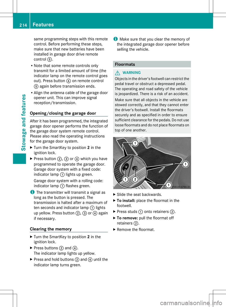
footwell.
X Press studs :onto retainers ;.
X To remove: pull the floormat off
retainers ;.
X Remove the floormat. 214
FeaturesStowage and features
Page 229 of 284
X
Open the trunk lid.
X Open the trunk partition (Y page 94).
X Lift the trunk floor upwards (Y page 206).
i Depending on the equipment, tools
required for a wheel change, such as a jack
or a lug wrench, are not available in all
vehicles. Tools approved for your vehicle
are available at a qualified specialist
workshop.
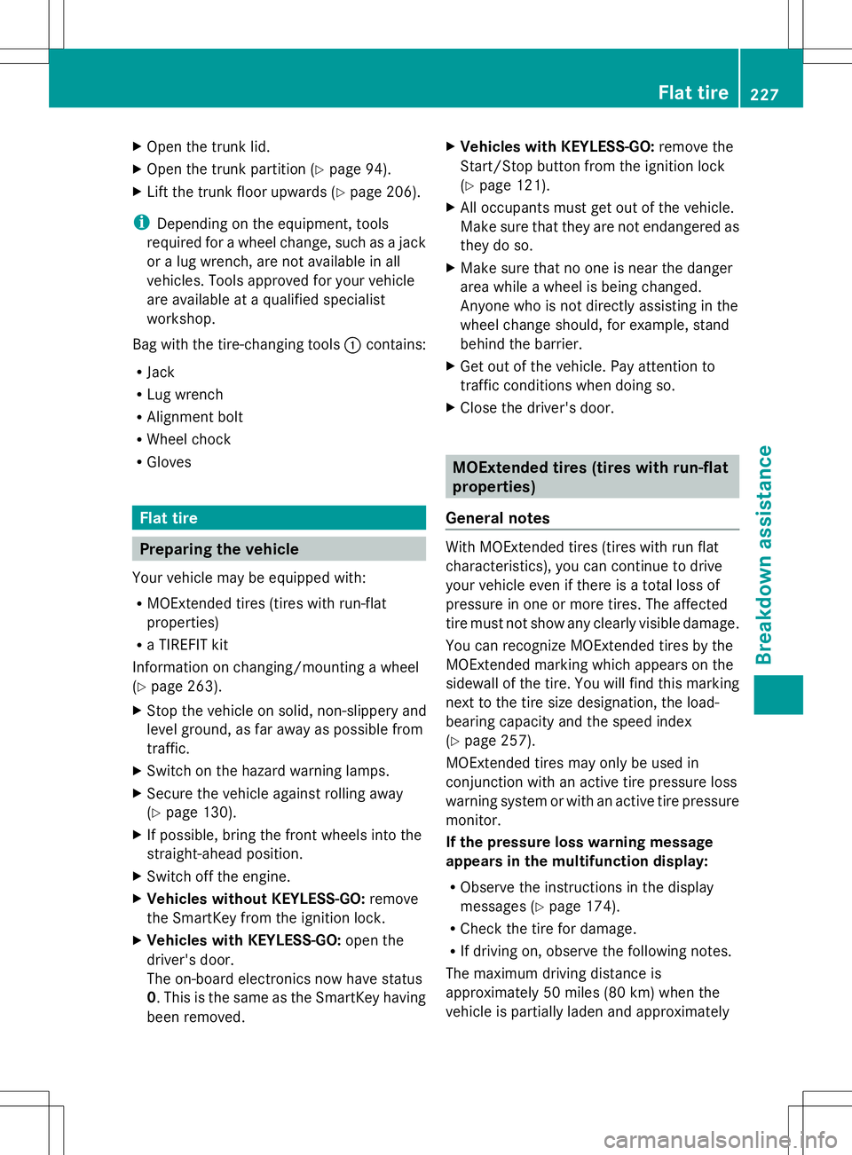
Bag with the tire-changing tools :contains:
R Jack
R Lug wrench
R Alignment bolt
R Wheel chock
R Gloves Flat tire
Preparing the vehicle
Your vehicle may be equipped with:
R MOExtended tires (tires with run-flat
properties)
R a TIREFIT kit
Information on changing/mounting a wheel
(Y page 263).
X Stop the vehicle on solid, non-slippery and
level ground, as far away as possible from
traffic.
X Switch on the hazard warning lamps.
X Secure the vehicle against rolling away
(Y page 130).
X If possible, bring the front wheels into the
straight-ahead position.
X Switch off the engine.
X Vehicles without KEYLESS-GO: remove
the SmartKey from the ignition lock.
X Vehicles with KEYLESS-GO: open the
driver's door.
The on-board electronics now have status
0. This is the same as the SmartKey having
been removed. X
Vehicles with KEYLESS-GO: remove the
Start/Stop button from the ignition lock
(Y page 121).
X All occupants must get out of the vehicle.
Make sure that they are not endangered as
they do so.
X Make sure that no one is near the danger
area while a wheel is being changed.
Anyone who is not directly assisting in the
wheel change should, for example, stand
behind the barrier.
X Get out of the vehicle. Pay attention to
traffic conditions when doing so.
X Close the driver's door. MOExtended tires (tires with run-flat
properties)
General notes With MOExtended tires (tires with run flat
characteristics), you can continue to drive
your vehicle even if there is a total loss of
pressure in one or more tires. The affected
tire must not show any clearly visible damage.
You can recognize MOExtended tires by the
MOExtended marking which appears on the
sidewall of the tire. You will find this marking
next to the tire size designation, the load-
bearing capacity and the speed index
(Y
page 257).
MOExtended tires may only be used in
conjunction with an active tire pressure loss
warning system or with an active tire pressure
monitor.
If the pressure loss warning message
appears in the multifunction display:
R Observe the instructions in the display
messages (Y page 174).
R Check the tire for damage.
R If driving on, observe the following notes.
The maximum driving distance is
approximately 50 miles (80 km) when the
vehicle is partially laden and approximately Flat tire
227Breakdown assistance
Page 240 of 284
!
Do not tow with sling-type equipment.
This could damage the vehicle.
! When towing vehicles with KEYLESS-GO,
use the key instead of the Start/Stop
button. Otherwise, the automatic
transmission may shift to position Pwhen
the driver's or front-passenger door are
opened, which could lead to damage to the
transmission.
! Make sure that the electric parking brake
is released. If the electric parking brake is
faulty, visit a qualified specialist workshop.
! The vehicle can be towed a maximum of
30 miles (50km). The towing speed of
30 mph (50 km/h) must not be exceeded.
If the vehicle has to be towed more than
30 miles (50km), the entire vehicle must be
raised and transported.
! If you tow or tow-start another vehicle, its
weight must not exceed the maximum
permissible gross vehicle weight of your
vehicle.
Information on your vehicle's gross vehicle
weight rating can be found on the vehicle
identification plate (Y page 274).
It is better to have the vehicle transported
than to have it towed.
The automatic transmission must be in
position Nwhen the vehicle is being towed.
The battery must be connected and charged.
Otherwise, you:
R cannot turn the SmartKey to position 2in
the ignition lock
R cannot shift the automatic transmission to
position N
i Disarm the automatic locking feature
before the vehicle is towed (Y page 161).
You could otherwise be locked out when
pushing or towing the vehicle. Installing/removing the towing eye
Installing the towing eye G
WARNING
The exhaust tail pipe may be very hot. There
is a risk of burns when removing the rear
cover.
Do not touch the exhaust pipe. Take particular
care when removing the rear cover. Example: towing eye mounting covers
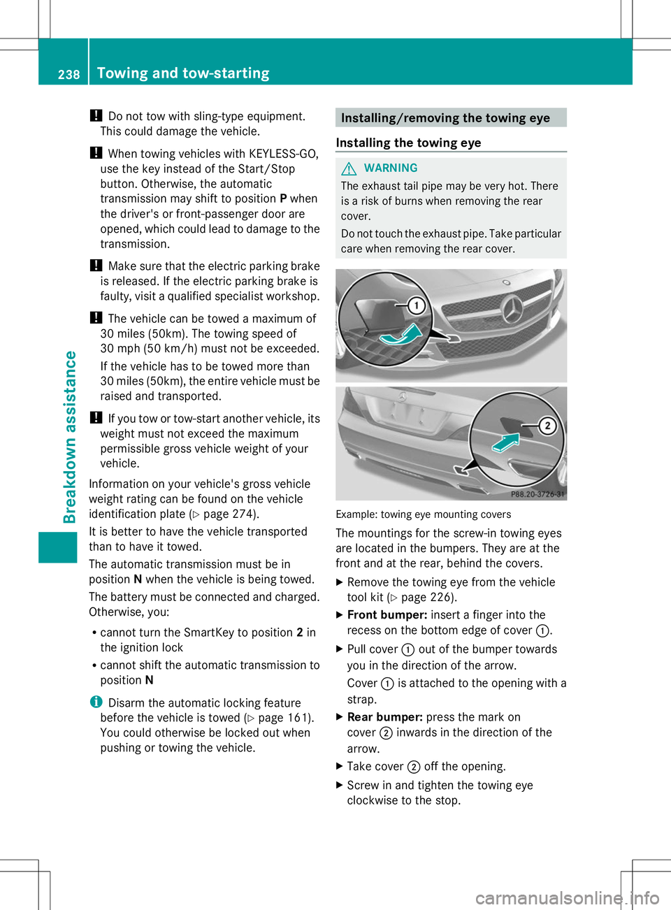
The mountings for the screw-in towing eyes
are located in the bumpers. They are at the
front and at the rear, behind the covers.
X Remove the towing eye from the vehicle
tool kit (Y page 226).
X Front bumper: insert a finger into the
recess on the bottom edge of cover :.
X Pull cover :out of the bumper towards
you in the direction of the arrow.
Cover :is attached to the opening with a
strap.
X Rear bumper: press the mark on
cover ;inwards in the direction of the
arrow.
X Take cover ;off the opening.
X Screw in and tighten the towing eye
clockwise to the stop. 238
Towing and tow-startingBreakdown assistance
Page 241 of 284
Removing the towing eye
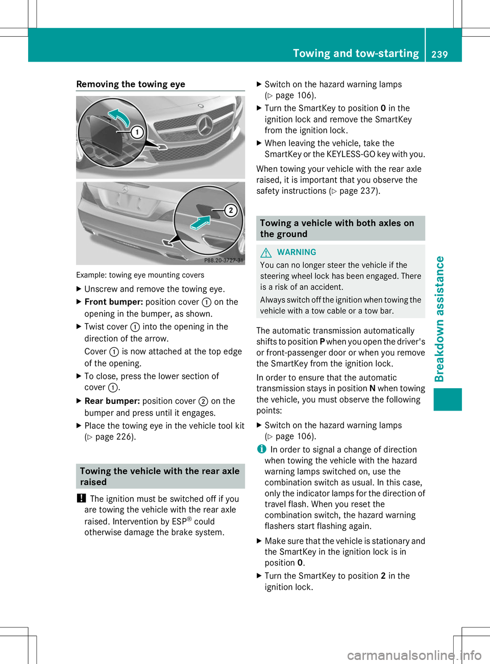
Example: towing eye mounting covers
X
Unscrew and remove the towing eye.
X Front bumper: position cover:on the
opening in the bumper, as shown.
X Twist cover :into the opening in the
direction of the arrow.
Cover :is now attached at the top edge
of the opening.
X To close, press the lower section of
cover :.
X Rear bumper: position cover;on the
bumper and press until it engages.
X Place the towing eye in the vehicle tool kit
(Y page 226). Towing the vehicle with the rear axle
raised
! The ignition must be switched off if you
are towing the vehicle with the rear axle
raised. Intervention by ESP ®
could
otherwise damage the brake system. X
Switch on the hazard warning lamps
(Y page 106).
X Turn the SmartKey to position 0in the
ignition lock and remove the SmartKey
from the ignition lock.
X When leaving the vehicle, take the
SmartKey or the KEYLESS-GO key with you.
When towing your vehicle with the rear axle
raised, it is important that you observe the
safety instructions (Y page 237). Towing a vehicle with both axles on
the ground
G
WARNING
You can no longer steer the vehicle if the
steering wheel lock has been engaged. There
is a risk of an accident.
Always switch off the ignition when towing the
vehicle with a tow cable or a tow bar.
The automatic transmission automatically
shifts to position Pwhen you open the driver's
or front-passenger door or when you remove
the SmartKey from the ignition lock.
In order to ensure that the automatic
transmission stays in position Nwhen towing
the vehicle, you must observe the following
points:
X Switch on the hazard warning lamps
(Y page 106).
i In order to signal a change of direction
when towing the vehicle with the hazard
warning lamps switched on, use the
combination switch as usual. In this case,
only the indicator lamps for the direction of
travel flash. When you reset the
combination switch, the hazard warning
flashers start flashing again.
X Make sure that the vehicle is stationary and
the SmartKey in the ignition lock is in
position 0.
X Turn the SmartKey to position 2in the
ignition lock. Towing and tow-starting
239Breakdown assistance Z
Page 266 of 284
Storing wheels
Store wheels that are not being used in a cool,
dry and preferably dark place. Protect the
tires from oil, grease, gasoline and diesel. Cleaning the wheels
G
WARNING
The water jet from a circular jet nozzle (dirt
blasters) can cause invisible exterior damage
to the tires or chassis components.
Components damaged in this way may fail
unexpectedly. There is a risk of an accident.
Do not use power washers with circular jet
nozzles to clean the vehicle. Have damaged
tires or chassis components replaced
immediately. Mounting a wheel
Preparing the vehicle X
Stop the vehicle on solid, non-slippery and
level ground.
X Unload the vehicle. The jack can only be
used when the vehicle is unladen.
X Apply the electric parking brake manually.
X Bring the front wheels into the straight-
ahead position.
X Shift the transmission to position P.
X Switch off the engine.
X Vehicles without KEYLESS-GO: remove
the SmartKey from the ignition lock.
X Vehicles with KEYLESS-GO: open the
driver's door.
The on-board electronics now have status
0. This is the same as the SmartKey having
been removed.
X Vehicles with KEYLESS-GO: remove the
Start/Stop button from the ignition lock
(Y page 121). X
If included in the vehicle equipment,
remove the tire-change tool kit from the
vehicle.
X Secure the vehicle to prevent it from rolling
away.
Securing the vehicle to prevent it from
rolling away If your vehicle is equipped with a wheel chock,
it can be found in the tire-change tool kit
(Y
page 226).
The folding wheel chock is an additional
securing measure to prevent the vehicle from
rolling away, for example when changing a
wheel.
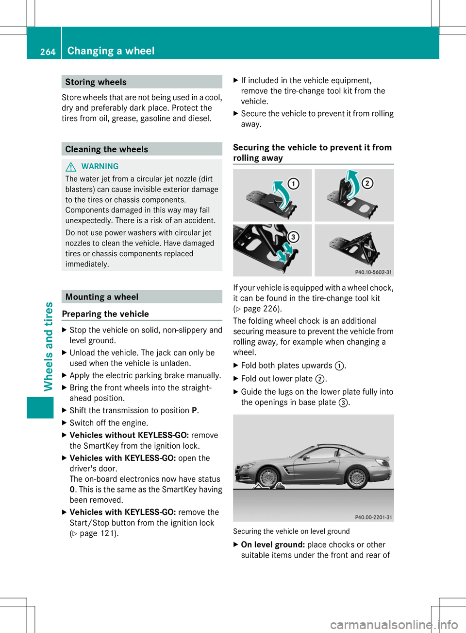
X Fold both plates upwards :.
X Fold out lower plate ;.
X Guide the lugs on the lower plate fully into
the openings in base plate =. Securing the vehicle on level ground
X On level ground: place chocks or other
suitable items under the front and rear of 264
Changing a wheelWheels and tires
Page 267 of 284
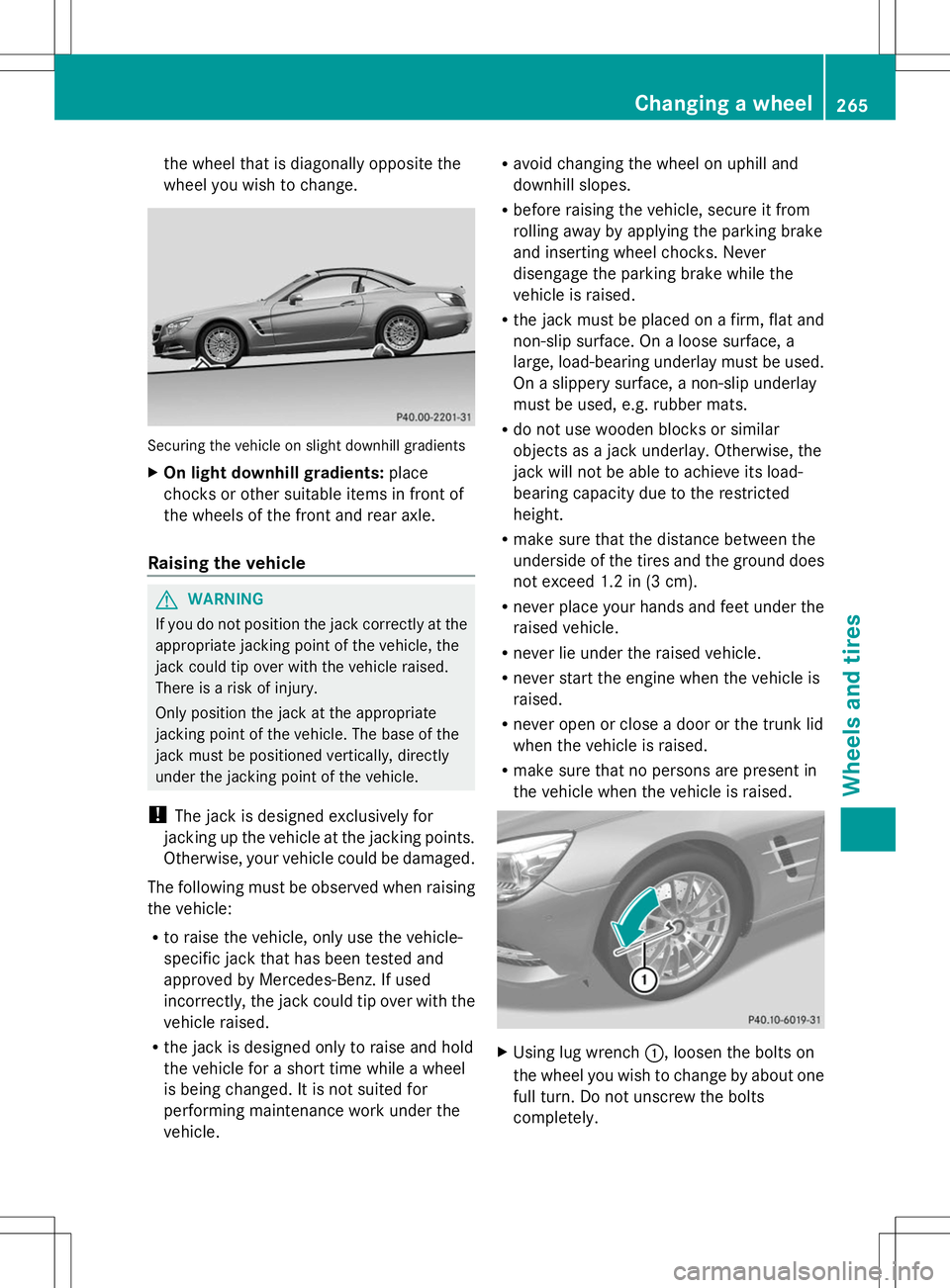
the wheel that is diagonally opposite the
wheel you wish to change.
Securing the vehicle on slight downhill gradients
X On light downhill gradients: place
chocks or other suitable items in front of
the wheels of the front and rear axle.
Raising the vehicle G
WARNING
If you do not position the jack correctly at the
appropriate jacking point of the vehicle, the
jack could tip over with the vehicle raised.
There is a risk of injury.
Only position the jack at the appropriate
jacking point of the vehicle. The base of the
jack must be positioned vertically, directly
under the jacking point of the vehicle.
! The jack is designed exclusively for
jacking up the vehicle at the jacking points.
Otherwise, your vehicle could be damaged.
The following must be observed when raising
the vehicle:
R to raise the vehicle, only use the vehicle-
specific jack that has been tested and
approved by Mercedes-Benz. If used
incorrectly, the jack could tip over with the
vehicle raised.
R the jack is designed only to raise and hold
the vehicle for a short time while a wheel
is being changed. It is not suited for
performing maintenance work under the
vehicle. R
avoid changing the wheel on uphill and
downhill slopes.
R before raising the vehicle, secure it from
rolling away by applying the parking brake
and inserting wheel chocks. Never
disengage the parking brake while the
vehicle is raised.
R the jack must be placed on a firm, flat and
non-slip surface. On a loose surface, a
large, load-bearing underlay must be used.
On a slippery surface, a non-slip underlay
must be used, e.g. rubber mats.
R do not use wooden blocks or similar
objects as a jack underlay. Otherwise, the
jack will not be able to achieve its load-
bearing capacity due to the restricted
height.
R make sure that the distance between the
underside of the tires and the ground does
not exceed 1.2 in (3 cm).
R never place your hands and feet under the
raised vehicle.
R never lie under the raised vehicle.
R never start the engine when the vehicle is
raised.
R never open or close a door or the trunk lid
when the vehicle is raised.
R make sure that no persons are present in
the vehicle when the vehicle is raised. X
Using lug wrench :, loosen the bolts on
the wheel you wish to change by about one
full turn. Do not unscrew the bolts
completely. Changing a
wheel
265Wheels an d tires Z