MERCEDES-BENZ SL600 2000 R129 Owner's Manual
Manufacturer: MERCEDES-BENZ, Model Year: 2000, Model line: SL600, Model: MERCEDES-BENZ SL600 2000 R129Pages: 297, PDF Size: 8.33 MB
Page 151 of 297
147 Soft top
Technical
data Instruments
and controlsOperationDrivingInstrument
cluster displayPractical hints Car care Index For safety reasons, the soft top cannot be unlocked
while driving.
However, if the soft top is not completely locked, it can
be locked while driving by pushing the soft/hardtop
switch forward.
If the indicator lamp in the soft top switch blinks while
activating the switch,
• the battery voltage may be insufficient - start engine
and let run while activating switch,
• the system may be overloaded (for example after
lowering or raising the soft top approx.
5 consecutive times) - after approx. 2 minutes the
soft top switch may be activated again,
• and the power supply was interrupted (battery
disconnected or empty), the soft top cannot be fully
raised or lowered.
To raise the soft top, for safety reasons, first remove key
from steering lock. Lower soft top by hand into
compartment, and resynchronize the power windows.
See page 116.
To lower the soft top, first resynchronize the power
windows. See page 116.If t he indicator la mp continues to bl ink, l ock th e sof t top
manually. See page 253.
Have the system checked at your authorized Mercedes-
Benz Center as soon as possible.
Note:
If the roll bar was raised automatically, the process of
raising or lowering the soft top will take somewhat
longer, as the roll bar must first be lowered.
Whenever possible, park vehicle in the shade as
continuous exposure to sun rays can prematurely
deteriorate the soft top material.
Permanent creases in the plastic window, caused by
storage of the soft top in the storage compartment,
cannot be avoided.
The soft top may become moldy if it is kept in the
storage compartment for an extended period.
Therefore, we recommend raising and airing it
thoroughly with the side windows open (do not expose
it to the sun) at regular intervals during the wet and
cold seasons.
Page 152 of 297
148 Wind screen
Technical
data Instruments
and controlsOperationDrivingInstrument
cluster displayPractical hints Car care Index
Wind screen
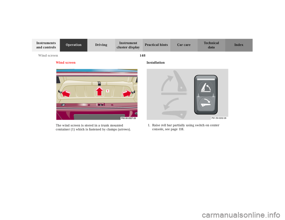
The wind screen is stored in a trunk mounted
container (1) which is fastened by clamps (arrows).Installation
1. Raise roll bar partially using switch on center
console, see page 118.
P91.59-0202-26
Page 153 of 297
149 Wind screen
Technical
data Instruments
and controlsOperationDrivingInstrument
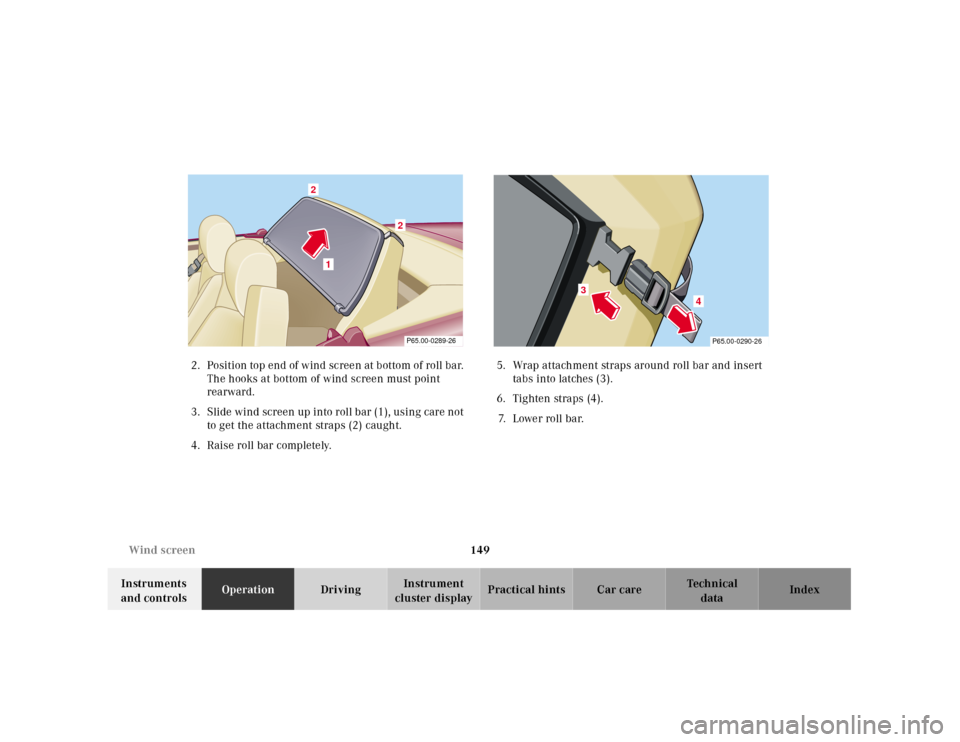
cluster displayPractical hints Car care Index 2. Position top end of w ind sc ree n at b ottom of roll ba r.
The hooks at bottom of wind screen must point
rearward.
3. Slide wind screen up into roll bar (1), using care not
to get the attachment straps (2) caught.
4. Raise roll bar completely.5. Wrap attachment straps around roll bar and insert
tabs into latches (3).
6. Tighten straps (4).
7. Lower roll bar.
1
2
2
P65.00-0289-26
4
3
P65.00-0290-26
Page 154 of 297
150 Wind screen
Technical
data Instruments
and controlsOperationDrivingInstrument
cluster displayPractical hints Car care Index
Setting up
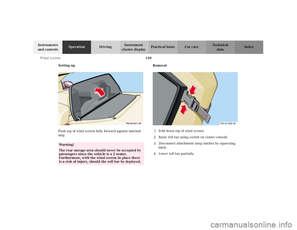
Push top of wind screen fully forward against internal
stop.Removal
1. Fold down top of wind screen.
2. Raise roll bar using switch on center console.
3. Disconnect attachment strap latches by squeezing
latch.
4. Lower roll bar partially.
Wa r n i n g !
The rear storage area should never be occupied by
passengers since the vehicle is a 2 seater.
Furthermore, with the wind screen in place there
is a risk of injury, should the roll bar be deployed.
P65.00-0292-26
Page 155 of 297
151 Wind screen
Technical
data Instruments
and controlsOperationDrivingInstrument
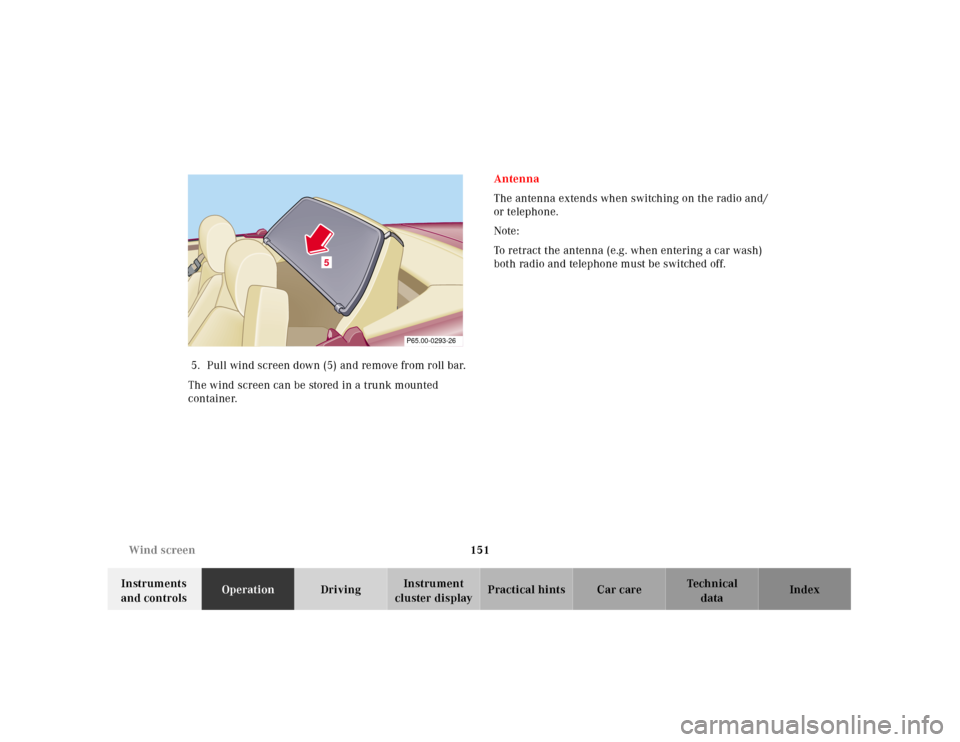
cluster displayPractical hints Car care Index 5. Pull wind screen down (5) and remove from roll bar.
The wind screen can be stored in a trunk mounted
container.Antenna
The antenna extends when switching on the radio and/
or telephone.
Note:
To retract the antenna (e.g. when entering a car wash)
both radio and telephone must be switched off.
5
P65.00-0293-26
Page 156 of 297
152 Contents – Driving
Technical
data Instruments
and controlsOperationDrivingInstrument
cluster displayPractical hints Car care Index
DrivingControl and operation of radio
transmitters ............................... 153
Radio, telephone and
two-way radio .............................. 153
The first 1 000 miles
(1 500 km) ................................. 154
Maintenance ................................... 154
Tele Aid ........................................... 155
Catalytic converter ........................ 163
Emission control ............................ 164
Steering lock ................................... 165
Starting and turning off
the engine .................................. 167
Before starting ............................ 167
Starting ........................................ 167
Turning off .................................. 167
Automatic transmission ............... 168
Driving ......................................... 168
Accelerator Position ................... 169
Selector lever positions ............. 169
Maneuvering ............................... 172
Stopping ....................................... 172Program mode
selector switch ........................... 173
Emergency Operation ................174
Parking brake ................................ 175
Driving instructions ....................... 176
Drive sensibly - Save fuel .......... 176
Drinking and driving ................. 176
Pedals ........................................... 176
Power assistance ........................ 177
Brakes .......................................... 177
Driving off ................................... 178
Parking ........................................ 178
Tires ............................................. 179
Aquaplaning ................................180
Tire traction .................................180
Tire speed rating ........................181
Snow chains ................................ 181
Ve h i c l e s w i t h s p o r t
package ........................................181
Winter driving
instructions .................................182
Winter driving .............................183
Block heater .................................183
Deep water ...................................184Traveling abroad ........................ 184
Cruise control ................................. 185
Brake assist system (BAS) ............ 188
Antilock brake system (ABS) ....... 190
ABS control ................................. 191
Electronic Stability Program
(ESP) ........................................... 192
Synchronizing ESP .................... 193
ESP Control Switch .................... 194
Level control system ...................... 196
Level control switch
positions ...................................... 196
Normal Level ............................... 197
Wheel Change Switch ............... 198
Adaptive Damping System
(ADS) ........................................... 199
Adaptive damping system
adjustment .................................. 199
What you should know at the gas
station .........................................200
Fuel supply ..................................200
Fuel ...............................................200
Check regularly and before
a long trip ...................................202
Page 157 of 297
153 Control and operation of radio transmitters
Technical
data Instruments
and controlsOperationDrivingInstrument
cluster displayPractical hints Car care Index Control and operation of radio transmitters
Radio, telephone and two-way radio
1 Observe all legal requirements.
Telephones and two-way radio
Radio transmitters, such as a portable telephone or a
citizens band unit should only be used inside the
vehicle if they are connected to an antenna that is
installed on the outside of the vehicle.
Refer to the radio transmitter operation instructions
regarding use of an external antenna.
Wa r n i n g !
Please do not forget that your primary
responsibility is to drive the vehicle. Only operate
the radio, telephone
1 or two-way radio
1 if road and
traffic conditions permit.
Bear in mind that at a speed of just 30 mph
(approximately 50 km/h), your vehicle is covering
a distance of approximately 50 feet (approximately
14 m ) e v e r y s e c o n d .
Wa r n i n g !
Never operate radio transmitters equipped with a
built-in or attached antenna (i.e. without being
connected to an external antenna) from inside the
vehicle while the engine is running. Doing so could
lead to a malfunction of the vehicle’s electronic
system, possibly resulting in an accident and
personal injury.
Page 158 of 297
154 The first 1 000 miles
Technical
data Instruments
and controlsOperationDrivingInstrument
cluster displayPractical hints Car care Index
The first 1 000 miles (1 500 km)
The more cautiously you treat your vehicle during the
break-in period, the more satisfied you will be with its
performance later on. Therefore, drive your vehicle
during the first 1 000 miles (1 500 km) at moderate
vehicle and engine speeds.
During this period, avoid heavy loads (full throttle
driving) and excessive engine speeds.
Avoid accelerating by kickdown. It is not recommended
to bra ke t he veh icl e by ma nu al ly shif ting to a l owe r gear.
We recommend that you select positions “3”, “2” or “1”
only at moderate speeds (for hill driving).
After 1 000 miles (1 500 km) speeds may be gradually
increased to the permissible maximum.Maintenance
Approximately 30 days or 2000 miles (2000 km) prior to
the next recommended service, the remaining distance
or days are displayed in the main odometer field. See
Flexible service system on page 80.
We strongly recommend that you have your vehicle
serviced by your authorized Mercedes-Benz Center, in
accordance with the Service Booklet at the times called
for by the FSS.
Failure to have the vehicle maintained in accordance
with the Service Booklet at the designated times/
mileage may result in vehicle damage not covered by
the Mercedes-Benz Limited Warranty.
Page 159 of 297
155 Tele Aid
Technical
data Instruments
and controlsOperationDrivingInstrument
cluster displayPractical hints Car care Index Tele Aid
Important!
The initial activation of the Tele Aid system may only be
performed by completing the subscriber agreement and
placing an acquaintance call using the “SOS” button.
Failure to complete either of these steps will result in a
system that is not activated.
If you have any questions regarding activation, please
call the Response Center at 1-800-756-9018 (in the USA)
or 1-888-923-8367 (in Canada).
(Telematic Alarm Identification on Demand)
The Tele Aid system consists of three types of response;
automatic and manual emergency, roadside assistance
and information.
The Tele Aid system is always operational, providing
that the vehicle’s battery is charged and properly
connected. To activate, press the “SOS” button, the
Roadside Assistance button or the Information
button¡, depending on the type of response
required.System self-check
Initially, after turning the key in steering lock to
position 2, malfunctions are detected and indicated (the
indicator lamps in the “SOS” button, the Roadside
Assistance button and the Information
button¡ stay on longer than 5 seconds or do not
come on).
If a malfunction is indicated as outlined above, have the
system checked at the nearest Mercedes-Benz Center as
soon as possible.
Important!
Always make sure that the indicator lamp in the
“SOS” button remains illuminated for approx. 5 seconds
during the system self-check after turning key in
steering lock to position 2.
Emergency calls
An emergency call is initiated automatically following
an accident in which the Emergency Tensioning
Retractors (ETR’s) or airbags deploy. An emergency call
can also be initiated manually by opening the cover next
to the interior rear view mirror labeled “SOS”, then
Page 160 of 297
156 Tele Aid
Technical
data Instruments
and controlsOperationDrivingInstrument
cluster displayPractical hints Car care Index
pressing the button (for longer than 2 seconds) located
under the cover. See below for instructions on initiating
an emergency call manually.
Once the emergency call is in progress, the indicator
lamp in the “SOS” button will begin to flash. All
information relevant to the emergency, such as the
location of the vehicle (determined by the GPS satellite
location system), vehicle model, identification number
and color are generated.
A voice connection between the Response Center and
the occupants of the vehicle will be established
automatically soon after the emergency call has been
initiated. The Response Center will attempt to determine
more precisely the nature of the accident provided they
can speak to an occupant of the vehicle.
The Tele Aid system is available if:
• it has been activated and is operational. Activation
requires a subscription for monitoring services and
cellular air time,
• t h e r e l ev a n t c e l l u l a r p h on e n e t w or k a n d G P S si g n a l s
are available.Note:
Location of the vehicle on a map is possible if the
vehicle is able to receive signals from the GPS satellite
network.
Wa r n i n g !
If the indicator lamp in the “SOS” button is
illuminated continuously and there was no voice
connection to the Response Center established,
then the Tele Aid system could not initiate an
emergency call (e.g. the relevant cellular phone
network is not available).Should this occur, assistance must be summoned
by other means.