spare tire MERCEDES-BENZ SL600 2000 R129 Owner's Manual
[x] Cancel search | Manufacturer: MERCEDES-BENZ, Model Year: 2000, Model line: SL600, Model: MERCEDES-BENZ SL600 2000 R129Pages: 297, PDF Size: 8.33 MB
Page 8 of 297

5 ContentsPassenger airbag
indicator lamp ............................. 213
Practical hintsFirst aid kit ..................................... 215
Stowing things in the vehicle ...... 215
Vehicle tools .................................... 216
Vehicle jack ..................................... 217
Fuses ................................................ 218
Hood ................................................. 219
Automatic transmission
fluid level ...................................221
Checking engine oil level .............221
Coolant level ...................................223
Adding coolant ...............................224
Windshield and headlamp
washer fluid mixing ratio ........225
Wheels .............................................226
Tire replacement ............................226
Rotating wheels ..............................227
Spare wheel ....................................228
Changing wheels ...........................230
Tire inflation pressure ..................234
Battery .............................................236Battery Recycling ....................... 237
Jump starting ................................. 238
Towing the vehicle ........................ 240
Exterior lamps ............................... 242
Headlamp assembly
(Halogen) .................................... 243
Taillamp assemblies .................. 249
Changing batteries in
the remote control .................... 251
Synchronizing ............................ 252
Raising soft top manually ............ 253
Replacing wiper blade insert ...... 257
Manual release of
fuel filler flap ............................ 259
Trunk lamp ..................................... 259
Vehicle careCleaning and care
of the vehicle ............................. 261
Power washer ............................. 262
Tar stains .................................... 262
Paintwork, Painted Body
Components ................................ 262
Engine cleaning ......................... 263Vehicle washing .........................263
Ornamental moldings ................263
Headlamps, taillamps,
turn signal lenses ......................263
Window cleaning .......................264
Light alloy wheels ......................264
Instrument cluster .....................264
Steering wheel and
gear selector lever ......................264
Cup holder ...................................264
Seat belts .....................................265
Headliner, shelf behind
roll bars, and other hard
plastic trim items .......................265
Soft top .........................................265
Headliner .....................................266
Wind screen ................................266
Automatic antenna .....................266
Wiper blade .................................266
Headlamp cleaning system .......266
Leather upholstery .....................267
Plastic and rubber parts ............267
Illuminated door sill panels .....267
Page 9 of 297

6 Contents
Technical dataSpare parts service ........................269
Warranty coverage .........................269
Identification labels .......................270
Layout of poly-V-belt drive ............ 271
Engine ..............................................272
Rims - Tires .....................................273
Weights ............................................275
Main Dimensions ...........................275Fuels, coolants, lubricants etc. -
capacities ....................................276
Engine oils ...................................... 278
Engine oil additives ...................... 278
Air conditioner refrigerant .......... 278
Brake fluid ...................................... 278
Premium unleaded gasoline ........ 279
Fuel requirements ........................ 279
Gasoline additives ......................... 280
Coolants .......................................... 280
Consumer information ................. 282
IndexIndex ................................................285
Page 162 of 297
158 Tele Aid
Technical
data Instruments
and controlsOperationDrivingInstrument
cluster displayPractical hints Car care Index
Roadside Assistance button
Located below the center armrest cover is the Roadside
Assistance button. Pressing and holding the
button (for longer than 2 seconds), will initiate a call to
a Mercedes-Benz Roadside Assistance dispatcher. The
button will flash while the call is in progress. The
Tele Aid system will transmit data generating the
vehicle identification number, model, color and location
(subject to availability of cellular and GPS signals).A voice connection between the Roadside Assistance
dispatcher and the occupants of the vehicle will be
established. The nature of the need for assistance can
then be described. Sign and Drive services (jump start, a
few gallons of fuel or the replacement of a flat tire with
the vehicle spare tire) are available.
If the vehicle requires more than Sign and Drive
services, the Mercedes-Benz Roadside assistance
dispatcher will either dispatch a qualified
Mercedes-Benz technician or arrange to tow your
vehicle to the nearest Mercedes-Benz Center.
For other than Sign and Drive services, labor and / or
towing charges may apply. Refer to the Roadside
Assistance manual for more information.
Notes:
The indicator lamp in the Roadside Assistance
button remains illuminated in red for approx.
5 seconds during the system self-check after turning
key in steering lock to position 2 (together with the
“SOS” button and the Information button¡).
See system self-check on page 155 when the indicator
lamp does not light up in red or stays on longer than
approximately 5 seconds.
Wa r n i n g !
If you feel at any way in jeopardy when in the
vehicle (e.g. smoke or fire in the vehicle, vehicle in
a dangerous road location), please do not wait for
voice contact after you have pressed the emergency
button. Carefully leave the vehicle and move to a
safe location. The Response Center will
automatically contact local emergency officials
with the vehicle’s approximate location if they
receive an “SOS” signal and cannot make voice
contact with the vehicle occupants.
Page 197 of 297
193 Driving systems
Technical
data Instruments
and controlsOperationDrivingInstrument
cluster displayPractical hints Car care Index Notes:
The malfunction indicator lamp for the ESP is combined
with that of the BAS.
The yellow BAS/ESP malfunction indicator lamp in the
instrument cluster and the yellow ESP warning
lampv in the speedometer dial come on with the
key in steering lock position 2. They should go out with
the engine running.
If the BAS/ESP malfunction indicator lamp comes on
permanently with the engine running, a malfunction
has been detected in either system. Pressing the
a ccelera tor peda l will require greater e ffort. Only partia l
engine output will be available.
If the BAS malfunctions, the brake system functions in
the usual manner, but without BAS.
If the BAS/ESP malfunction indicator lamp come s on,
have the BAS or ESP checked at your authorized
Mercedes-Benz Center as soon as possible.
With the ABS malfunctioning, the ESP is also switched
off.Driving the vehicle with varied size tires will cause the
wheels to rotate at different speeds, therefore the ESP
may activate (yellow ESP warning lamp in speedometer
dial comes on). For this reason, all wheels, including the
spare wheel, must have the same tire outside diameter.
When testing the parking brake on a brake test
dynamometer, the engine must be shut off. Otherwise,
the ESP will immediately be engaged and will apply the
rear wheel brakes.
In winter operation, the maximum effectiveness of the
ESP is only achieved with Mercedes-Benz recommended
M+S rated radial-ply tires and/or snow chains.
Synchronizing ESP
If the power supply was interrupted (battery
disconnected or empty), the BAS/ESP malfunction
indicator lamp may be illuminated with the engine
running.
Turn steering wheel completely to the left and then to
the right. The BAS/ESP malfunction indicator lamp
should go out.
Page 218 of 297
214 Contents – Practical hints
Technical
data Instruments
and controlsOperation DrivingInstrument
cluster displayPractical hintsCar careIndex
Practical hintsFirst aid kit ..................................... 215
Stowing things in the vehicle ...... 215
Vehicle tools .................................... 216
Vehicle jack ..................................... 217
Fuses ................................................ 218
Hood ................................................. 219
Automatic transmission
fluid level ...................................221
Checking engine oil level .............221
Coolant level ...................................223
Adding coolant ...............................224Windshield and headlamp
washer f luid mixing ratio ....... 225
Wheels ............................................ 226
Tire replacement ........................... 226
Rotating wheels ............................. 227
Spare wheel .................................... 228
Changing wheels ........................... 230
Tire inflation pressure ................. 234
Battery ............................................. 236
Battery Recycling ....................... 237
Jump starting ................................. 238
Towing the vehicle ........................ 240Exterior lamps ................................242
Headlamp assembly
(Halogen) .....................................243
Taillamp assemblies ..................249
Changing batteries in
the remote control .................... 251
Synchronizing ............................252
Raising soft top manually .............253
Replacing wiper blade insert .......257
Manual release of
fuel filler flap .............................259
Trunk lamp .....................................259
Page 230 of 297
226 Tires, Wheels
Technical
data Instruments
and controlsOperation DrivingInstrument
cluster displayPractical hintsCar care Index
Wheels
Replace rims or tires with the same designation,
manufacturer and type as shown on the original part.
See your authorized Mercedes-Benz Center for further
information.
See your authorized Mercedes-Benz Center for
information on tested and recommended rims and tires
for summer and winter operation. They can also offer
advice concerning tire service and purchase.Tire replacement
Front and rear tires should be replaced in sets.
Furthermore - in the event of tire replacement - the
spare wheel (except Sport Package version), if possible,
should be used on the rear axle. Rims and tires must be
of the correct size and type. For dimensions, see
page 273.
We recommend that you break in new tires for approx.
60 miles (100 km) at moderate speed.
It is imperative that the wheel mounting bolts be
fastened to a tightening torque of 80 ft.lb. (110 Nm)
whenever wheels are mounted.
For rim and tire specifications, see page 273.
Page 232 of 297
228 Tires, Wheels
Technical
data Instruments
and controlsOperation DrivingInstrument
cluster displayPractical hintsCar care Index
Thoroughly clean the inner side of the wheels any time
you rotate the wheels or wash the vehicle underside.
The use of retread tires is not recommended. Retread
tires may adversely affect the handling characteristics
and safety of the vehicle.
Dented or bent rims can cause tire pressure loss and
d ama ge to th e tire bead s. For t his reason, ch eck rims for
damage at regular intervals. The rim f langes must be
checked for wear before a tire is mounted. Remove
burrs, if any.
Check and ensure proper tire inflation pressure after
rotating the wheels. For tire inf lation pressure see
page 234.Spare wheel
(except Sport Package)
The spare wheel rim size is 8
1/4 J x 17 H2.
In the case of a f lat tire, or breakdown, you may
temporarily use the spare wheel.
Unid irectional tires must a lways be mou nted w it h a rrow
on tire sidewall pointing in direction of vehicle forward
movement.
If the arrow on tire sidewall does not point in direction
of vehicle forward movement when using the spare
wheel, observe the following restrictions:
• Drive to the nearest repair facility to have the flat
tire repaired or replaced as appropriate.
• Do not operate vehicle with more than one spare
wheel mounted.
For additional information, refer to page 273.
Wa r n i n g !
The spare wheel rim is for temporary use only. Use
for over a total of 12 000 miles (20 000 km)
(aggregate of all uses) may cause wheel rim failure
leading to an accident and possible injuries.
Page 233 of 297
229 Tires, Wheels
Technical
data Instruments
and controlsOperation DrivingInstrument
cluster displayPractical hintsCar care Index Spare Wheel
(with Sport Package)
The spare wheel rim size is 8
1/4 J x 17 H2 with tire size
245/45 R 17 95W.
In the case of a f lat tire or breakdown, you may
temporarily use the spare wheel.
Unidirectional tires must always be mounted with arrow
on tire sidewall pointing in direction of vehicle forward
movement. If the arrow on tire sidewall does not point
in direction of vehicle forward movement when using
the spare wheel, observe the following restrictions:
• Do not exceed vehicle speed of 50 mph (80 km/h).
• Drive to the nearest repair facility to have the flat
tire repaired or replaced as appropriate.
• Do not operate vehicle with more than one spare
wheel mounted.
For additional information, refer to page 273.
Wa r n i n g !
The spare wheel rim is for temporary use only. Use
for over a total of 12 000 miles (20 000 km) may
cause wheel rim failure leading to an accident and
possible injuries. The dimensions of the spare wheel are different
from those of road wheels. As a result, the vehicle
handling characteristics change when driving with
a mounted spare wheel.The spare wheel should only be used temporarily,
and replaced with a regular road wheel as quickly
as possible.
Page 236 of 297
232 Tires, Wheels
Technical
data Instruments
and controlsOperation DrivingInstrument
cluster displayPractical hintsCar care Index
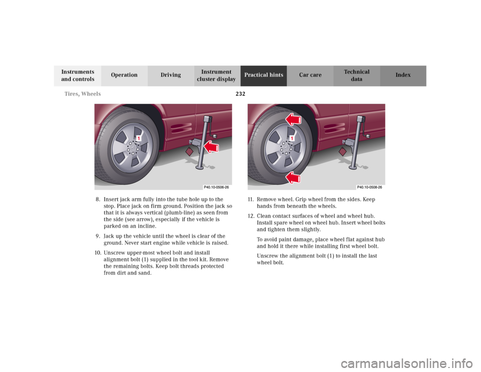
8. Insert jack arm fully into the tube hole up to the
stop. Place jack on firm ground. Position the jack so
that it is always vertical (plumb-line) as seen from
the side (see arrow), especially if the vehicle is
parked on an incline.
9. Jack up the vehicle until the wheel is clear of the
ground. Never start engine while vehicle is raised.
10. Unscrew upper-most wheel bolt and install
alignment bolt (1) supplied in the tool kit. Remove
the remaining bolts. Keep bolt threads protected
from dirt and sand.11. Remove wheel. Grip wheel from the sides. Keep
hands from beneath the wheels.
12. Clean contact surfaces of wheel and wheel hub.
Install spare wheel on wheel hub. Insert wheel bolts
and tighten them slightly.
To avoid paint damage, place wheel f lat against hub
and hold it there while installing first wheel bolt.
Unscrew the alignment bolt (1) to install the last
wheel bolt.
Page 237 of 297
233 Tires, Wheels
Technical
data Instruments
and controlsOperation DrivingInstrument
cluster displayPractical hintsCar care Index 13. Lower vehicle. Remove jack and insert jack tube
cover.
Before storing the jack, the jack arm must be
lowered almost to the base of the jack.
Store the spare wheel first and then the vehicle jack.
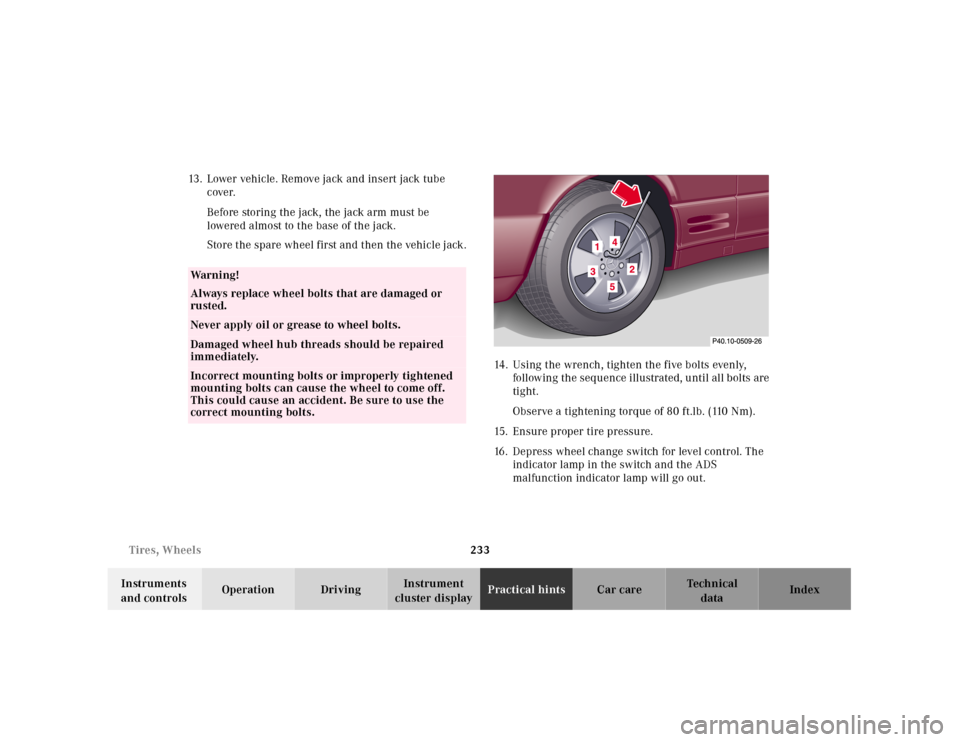
14. Using the wrench, tighten the five bolts evenly,
following the sequence illustrated, until all bolts are
tight.
Observe a tightening torque of 80 ft.lb. (110 Nm).
15. Ensure proper tire pressure.
16. Depress wheel change switch for level control. The
indicator lamp in the switch and the ADS
malfunction indicator lamp will go out.
Wa r n i n g !
Always replace wheel bolts that are damaged or
rusted.Never apply oil or grease to wheel bolts.Damaged wheel hub threads should be repaired
immediately.Incorrect mounting bolts or improperly tightened
mounting bolts can cause the wheel to come off.
This could cause an accident. Be sure to use the
correct mounting bolts.