service reset MERCEDES-BENZ SLC 2019 Owners Manual
[x] Cancel search | Manufacturer: MERCEDES-BENZ, Model Year: 2019, Model line: SLC, Model: MERCEDES-BENZ SLC 2019Pages: 306, PDF Size: 15 MB
Page 7 of 306
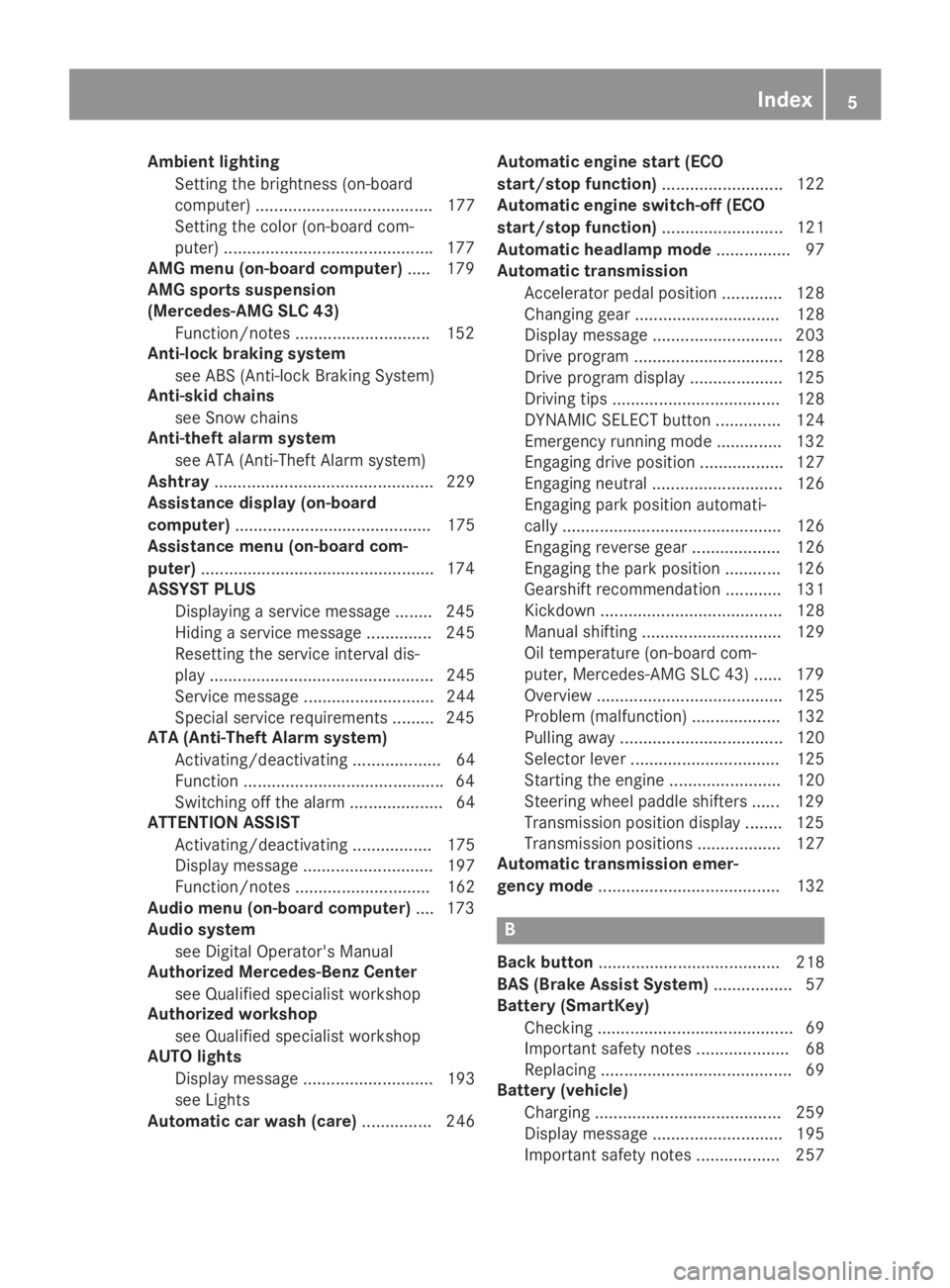
Ambient lighting
Setting the brightness (on-board
computer) ...................................... 177
Setting the color (on-board com-
puter) .............................................177
AMG menu (on-board computer)..... 179
AMG sports suspension
(Mercedes-AMG SLC 43)
Function/notes .............................152
Anti-lock braking system
see ABS (Anti-lock Braking System)
Anti-skid chains
see Snow chains
Anti-theft alarm system
see ATA (Anti-Theft Alarm system)
Ashtray............................................... 229
Assistance display (on-board
computer).......................................... 175
Assistance menu (on-board com-
puter)..................................................174
ASSYST PLUS
Displaying a service message ........245
Hiding a service message .............. 245
Resetting the service interval dis-
play ................................................ 245
Service message ............................ 244
Special service requirements ......... 245
ATA (Anti-Theft Alarm system)
Activating/deactivating ................... 64
Function ...........................................64
Switching off the alarm .................... 64
ATTENTION ASSIST
Activating/deactivating ................. 175
Display message ............................ 197
Function/notes............................. 162
Audio menu (on-board computer).... 173
Audio system
see Digital Operator's Manual
Authorized Mercedes-Benz Center
see Qualified specialist workshop
Authorized workshop
see Qualified specialist workshop
AUTO lights
Display message ............................ 193
see Lights
Automatic car wash (care)............... 246
Automatic engine start (ECO
start/stop function).......................... 122
Automatic engine switch-off (ECO
start/stop function).......................... 121
Automatic headlamp mode................ 97
Automatic transmission
Accelerator pedal position ............. 128
Changing gear ............................... 128
Display message ............................ 203
Drive program ................................ 128
Drive program display .................... 125
Driving tips .................................... 128
DYNAMIC SELECT button .............. 124
Emergency running mode.............. 132
Engaging drive position .................. 127
Engaging neutral ............................ 126
Engaging park position automati-
cally ............................................... 126
Engaging reverse gear ................... 126
Engaging the park position ............ 126
Gearshift recommendation ............ 131
Kickdown ....................................... 128
Manual shifting .............................. 129
Oil temperature (on-board com-
puter, Mercedes-AMG SLC 43) ...... 179
Overview ........................................ 125
Problem (malfunction) ................... 132
Pulling away ................................... 120
Selector lever ................................ 125
Starting the engine ........................ 120
Steering wheel paddle shifters ...... 129
Transmission position display ........ 125
Transmission positions .................. 127
Automatic transmission emer-
gency mode....................................... 132
B
Back button....................................... 218
BAS (Brake Assist System)................. 57
Battery (SmartKey)
Checking .......................................... 69
Important safety notes .................... 68
Replacing ......................................... 69
Battery (vehicle)
Charging ........................................ 259
Display message ............................ 195
Important safety notes .................. 257
Index5
Page 19 of 306
Important safety information ........... 75
Opening/closing (all) ....................... 76
Opening/closing (front) ................... 76
Overview .......................................... 75
Problem (malfunction) .....................78
Resetting .........................................77
Reversing feature .............................75
SIRIUS services
see also Digital Operator's Man-
ual .................................................. 217
SmartKey
Changing the battery ....................... 69
Changing the programming .............67
Checking the battery .......................69
Display message ............................ 206
Door central locking/unlocking ....... 66
Important safety notes.................... 66
Loss ................................................. 70
Mechanical key ................................ 68
Opening/closing the roof................ 80
Overview .......................................... 66
Positions (ignition lock) ................. 118
Problem (malfunction) ..................... 70
Starting the engine ........................ 120
SMS
see also Digital Operator's Man-
ual .................................................. 217
Snow chains...................................... 270
Sockets
Center console .............................. 230
General notes ................................ 229
Sound
Switching on/off........................... 218
Special seat belt retractor.................. 54
Specialist workshop............................ 27
Speed, controlling
see Cruise control
Speedometer
Digital ............................................ 171
In the Instrument cluster ................. 32
Segments ...................................... 167
Selecting the display unit............... 176
Sport handling mode
Activating/deactivating
(Mercedes-AMG SLC 43) ................. 62
Warning lamp ................................. 212
Standing lamps
Display message ............................ 193
Switching on/off.............................. 98
Start/stop function
see ECO start/stop function
Starting (engine)................................ 119
Steering
Display message ............................ 205
Steering wheel
Adjusting (electrically) ..................... 90
Adjusting (manually) ........................ 90
Button overview ............................... 33
Buttons (on-board computer) ......... 168
Important safety notes .................... 89
Storing settings (memory func-
tion) ................................................. 95
Steering wheel paddle shifters........ 129
Stopwatch (RACETIMER)................... 180
Stowage areas................................... 225
Stowage compartments
Armrest (under) ............................. 225
Center console .............................. 226
Cup holders ................................... 227
Door ............................................... 226
Eyeglasses compartment ............... 226
Glove box ....................................... 225
Important safety information ......... 225
Rear wall ........................................ 226
Stowage net ................................... 226
Stowage net....................................... 226
Summer tires..................................... 269
Sun visor............................................ 228
Surround lighting (on-board com-
puter).................................................. 177
SVHC (Substances of Very High
Concern)............................................... 27
Switching air-recirculation mode
on/off................................................. 114
Switching on media mode
Via the device list .......................... 223
T
Tachometer........................................ 167
Tail lamps
Display message ............................ 193
see Lights
Tank content
Fuel gauge ....................................... 32
Index17
Page 21 of 306
GVW (Gross Vehicle Weight) (def-
inition) ...........................................287
GVWR (Gross Vehicle Weight
Rating) (definition) ......................... 287
Important safety notes .................. 267
Increased vehicle weight due to
optional equipment (definition) ...... 286
Information on driving .................... 267
Kilopascal (kPa) (definition) ........... 287
Labeling (overview)........................ 283
Load bearing index (definition) ...... 288
Load index ..................................... 285
Load index (definition) ................... 287
M+S tires....................................... 269
Maximum load on a tire (defini-
tion) ............................................... 287
Maximum loaded vehicle weight
(definition) ..................................... 287
Maximum permissible tire pres-
sure (definition) ............................. 287
Maximum tire load ......................... 285
Maximum tire load (definition) ....... 287
MOExtended tires.......................... 269
Optional equipment weight (defi-
nition) ............................................ 288
Overview ........................................ 267
PSI (pounds per square inch)
(definition) ..................................... 287
Replacing ....................................... 288
Service life ..................................... 268
Sidewall (definition) ....................... 288
Speed rating (definition) ................ 287
Storing ........................................... 289
Structure and characteristics
(definition) ..................................... 286
Summer tires ................................. 269
Temperature .................................. 282
TIN (Tire Identification Number)
(definition) ..................................... 288
Tire bead (definition) ...................... 288
Tire pressure (definition) ................ 287
Tire pressures (recommended) ...... 286
Tire size (data)............................... 292
Tire size designation, load-bear-
ing capacity, speed rating .............. 283
Tire tread ....................................... 268
Tire tread (definition) ..................... 288
Total load limit (definition) ............. 288
Traction ......................................... 282
Traction (definition) ....................... 288
Tread wear ..................................... 282
Uniform Tire Quality Grading
Standards ...................................... 281
Uniform Tire Quality Grading
Standards (definition) .................... 286
Wear indicator (definition) ............. 288
Wheel and tire combination ........... 292
Wheel rim (definition) .................... 287
see Flat tire
Tow-starting
Emergency engine starting ............ 265
Important safety notes .................. 263
Towing
Permitted towing methods ............ 264
Towing away
Important safety guidelines ........... 263
Installing the towing eye ................ 263
Removing the towing eye ............... 264
Transporting the vehicle ................ 265
With both axles on the ground ....... 264
With the rear axle raised ................ 264
Traffic reports
see also Digital Operator's Man-
ual .................................................. 217
Transmission
Overview of transmission posi-
tions .............................................. 125
Selector lever ................................ 125
see Automatic transmission
Transmission position display......... 125
Transporting the vehicle.................. 265
Trip computer (on-board com-
puter).................................................. 170
Trip odometer
Calling up ....................................... 170
Resetting (on-board computer) ...... 171
Trunk
Emergency release .......................... 74
Important safety notes .................... 73
Locking separately ........................... 74
Opening/closing (manually from
outside) ............................................ 74
Overview .......................................... 73
Trunk lid
Display message ............................ 204
Opening dimensions ...................... 303
Index19
Page 29 of 306
ing interference that may cause undesiredoperation of the device."
Diagnostics connection
The diagnostics connection is used for con-necting diagnostic equipment at a qualifiedspecialist workshop.
GWARNING
If you connect equipment to a diagnostics
connection in the vehicle, it may affect the
operation of vehicle systems. As a result,
the operating safety of the vehicle could be
affected. There is a risk of an accident.
Only connect equipment to a diagnostics
connection in the vehicle, which is approved
for your vehicle by Mercedes-Benz.
GWARNING
Objects in the driver's footwell may restrict
the clearance around the pedals or block a
depressed pedal. This jeopardizes the oper-
ating and road safety of the vehicle. There is
a risk of an accident.
Stow all objects securely in the vehicle so
that they do not get into the driver's foot-
well. When using floormats or carpets, make
sure that they are properly secured so that
they do not slip or obstruct the pedals. Do
not place several floormats or carpets on
top of one another.
!If the engine is switched off and equip-ment on the diagnostics connection is used,the starter battery may discharge.
Connecting equipment to the diagnostics con-nection can lead to emissions monitoringinformation being reset, for example. This maylead to the vehicle failing to meet the require-ments of the next emissions test during themain inspection.
Qualified specialist workshop
An authorized Mercedes-Benz Center is aqualified specialist workshop. It has the neces-sary specialist knowledge, tools and qualifica-tions to correctly carry out the work required
on your vehicle. This is especially the case forwork relevant to safety.
Observe the notes in the Maintenance Book-let.
Always have the following work carried out atan authorized Mercedes-Benz Center:
Rwork relevant to safety
Rservice and maintenance work
Rrepair work
Ralterations, installation work and modifica-tions
Rwork on electronic components
Correct use
If you remove any warning stickers, you or oth-ers could fail to recognize certain dangers.Leave warning stickers in position.
Observe the following information when driv-ing your vehicle:
Rthe safety notes in this manual
Rtechnical data for the vehicle
Rtraffic rules and regulations
Rlaws and safety standards pertaining tomotor vehicles
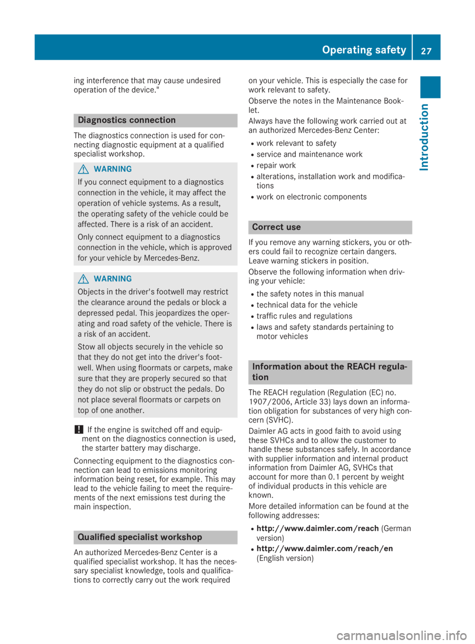
Information about the REACH regula-
tion
The REACH regulation (Regulation (EC) no.1907/2006, Article 33) lays down an informa-tion obligation for substances of very high con-cern (SVHC).
Daimler AG acts in good faith to avoid usingthese SVHCs and to allow the customer tohandle these substances safely. In accordancewith supplier information and internal productinformation from Daimler AG, SVHCs thataccount for more than 0.1 percent by weightof individual products in this vehicle areknown.
More detailed information can be found at thefollowing addresses:
Rhttp://www.daimler.com/reach(Germanversion)
Rhttp://www.daimler.com/reach/en(English version)
Operating safety27
Introduction
Z
Page 247 of 306
Maintaining the time-dependent service sched-ule:
XNote down the service due date displayed inthe multifunction display before disconnect-ing the battery.
or
XAfter reconnecting the battery, subtract thebattery disconnection periods from the ser-vice date shown on the display.
Hiding service displays
XPress the�vor�8button on the steer-ing wheel.
Showing service displays
XSwitch on the ignition.
XPress�Yor�eon the steering wheelto select theServ.Serv.menu.
XPress�cor�dto select theASSYSTASSYSTPLUSPLUSsubmenu and confirm by pressing the�vbutton.The service due date appears in the multi-function display.
Information about Service
Resetting the ASSYST PLUS service
interval display
!If the ASSYST PLUS service interval dis-play has been inadvertently reset, this set-ting can be corrected at a qualified special-ist workshop.
Have service work carried out as describedin the Maintenance Booklet. This may other-wise lead to increased wear and damage tothe major assemblies or the vehicle.
A qualified specialist workshop, e.g. an author-ized Mercedes-Benz Center, will reset theASSYST PLUS service interval display after theservice work has been carried out. You canalso obtain further information on mainte-nance work, for example.
Special service requirements
The specified maintenance interval takes onlythe normal operation of the vehicle intoaccount. Service work will need to be per-formed more often if the vehicle is operatedunder arduous conditions or increased loads.
The ASSYST PLUS service interval display isonly an aid. The driver of the vehicle is respon-sible for whether service work will need to beperformed more frequently than required as aresult of the actual operating conditionsand/or loads.
Examples of arduous operating conditions:
Rregular city driving with frequent intermedi-ate stops
Rthe vehicle is primarily used to travel shortdistances
Rfrequent use in mountainous terrain or onpoor road surfaces
Rthe engine is often left idling for long peri-ods
Rparticularly dusty conditions, or if air-recir-culation mode is frequently used
In these or similar operating conditions, havethe interior filter, air filter, engine oil and oil fil-ter, for example, changed more frequently.Under arduous operating conditions, the tiresmust be checked more often. Further informa-tion can be obtained at a qualified specialistworkshop.
Driving abroad
An extensive Mercedes-Benz Service networkis also available in other countries. You canobtain further information from any authorizedMercedes-Benz Service Center.
Care
Notes on care
HEnvironmental note
Dispose of empty packaging and cleaning
cloths in an environmentally responsible
manner.
!When cleaning your car, do not use:
Rdry, coarse or hard cloths
Rabrasive cleaning agents
Care245
Maintenance and care
Z
Page 261 of 306
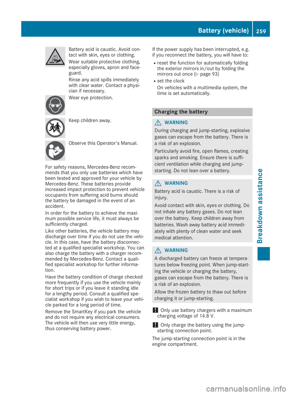
Battery acid is caustic. Avoid con-tact with skin, eyes or clothing.
Wear suitable protective clothing,especially gloves, apron and face-guard.
Rinse any acid spills immediatelywith clear water. Contact a physi-cian if necessary.
Wear eye protection.
Keep children away.
Observe this Operator's Manual.
For safety reasons, Mercedes-Benz recom-mends that you only use batteries which havebeen tested and approved for your vehicle byMercedes-Benz. These batteries provideincreased impact protection to prevent vehicleoccupants from suffering acid burns shouldthe battery be damaged in the event of anaccident.
In order for the battery to achieve the maxi-mum possible service life, it must always besufficiently charged.
Like other batteries, the vehicle battery maydischarge over time if you do not use the vehi-cle. In this case, have the battery disconnec-ted at a qualified specialist workshop. You canalso charge the battery with a charger recom-mended by Mercedes-Benz. Contact a quali-fied specialist workshop for further informa-tion.
Have the battery condition of charge checkedmore frequently if you use the vehicle mainlyfor short trips or if you leave it standing idlefor a lengthy period. Consult a qualified spe-cialist workshop if you wish to leave your vehi-cle parked for a long period of time.
Remove the SmartKey if you park the vehicleand do not require any electrical consumers.The vehicle will then use very little energy,thus conserving battery power.
If the power supply has been interrupted, e.g.if you reconnect the battery, you will have to:
Rreset the function for automatically foldingthe exterior mirrors in/out by folding themirrors out once (Ypage 93)
Rset the clock
On vehicles with a multimedia system, thetime is set automatically.
Charging the battery
GWARNING
During charging and jump-starting, explosive
gases can escape from the battery. There is
a risk of an explosion.
Particularly avoid fire, open flames, creating
sparks and smoking. Ensure there is suffi-
cient ventilation while charging and jump-
starting. Do not lean over a battery.
GWARNING
Battery acid is caustic. There is a risk of
injury.
Avoid contact with skin, eyes or clothing. Do
not inhale any battery gases. Do not lean
over the battery. Keep children away from
batteries. Wash away battery acid immedi-
ately with plenty of clean water and seek
medical attention.
GWARNING
A discharged battery can freeze at tempera-
tures below freezing point. When jump-start-
ing the vehicle or charging the battery,
gases can escape from the battery. There is
a risk of an explosion.
Allow the frozen battery to thaw out before
charging it or jump-starting.
!Only use battery chargers with a maximumcharging voltage of 14.8V.
!Onlycharge the battery using the jump-starting connection point.
The jump-starting connection point is in theengine compartment.
Battery (vehicle)259
Breakdown assistance
Z