fuel cap MERCEDES-BENZ SLK-Class 2013 R172 Owner's Manual
[x] Cancel search | Manufacturer: MERCEDES-BENZ, Model Year: 2013, Model line: SLK-Class, Model: MERCEDES-BENZ SLK-Class 2013 R172Pages: 358, PDF Size: 4.61 MB
Page 11 of 358
Emissions control
Service and warranty information ....20
Engine
Check Engine warning lamp ........... 250
Display message ............................ 226
ECO start/stop function ................139
Engine number ............................... 348
Irregularr unning............................ 143
Jump-starting ................................. 299
Starting problems ..........................143
Starting the engine with the
SmartKey ....................................... 137
Starting with KEYLESS-GO .............138
Switching off .................................. 156
Tow-starting (vehicle) ..................... 303
Engine electronics
Problem (malfunction) ...................143
Engine jump starting
see Jump starting (engine)
Engine oil
Adding ........................................... 278
Additives ........................................ 351
Checking the oil level ..................... 277
Checking the oil level using the
dipstick .......................................... 278
Display message ............................ 227
Filling capacity ............................... 350
Notes about oil grades ................... 350
Notes on oil level/consumption ....277
Temperature (on-board computer) .207
Viscosity ........................................ 351
ESP ®
(Electronic Stability
Program) AMG menu (on-board computer) ...208
Deactivating/activating (AMG
vehicles) .......................................... 63
Deactivating/activating (notes;
except AMG vehicles) ......................62
Display message ............................ 212
ETS .................................................. 62
Function/notes ................................ 61
Important safety information ...........61
Warning lamp ................................. 246
ETS (Electronic Traction System) ....... 62
Exhaus tcheck ................................... 159
Exhaus ttail pipe (cleaning
instructions) ...................................... 285Exterior lighting
Setting options .............................. 106
see Lights
Exterior mirrors
Adjusting ....................................... 100
Dipping (automatic) .......................101
Folding in/ou t(automatically) .......101
Folding in/ou t(electrically) ...........101
Folding in whe nlocking (on-board
computer) ...................................... 207
Out of position (troubleshooting) ...101
Storing settings (memory function) 103
Storing the parking position ..........102
Eyeglasses compartment .................257 F
Fille rcap
see Fuel filler flap
Filling capacities (Technical data) ...348
Fire extinguisher ............................... 291
First-aid kit ......................................... 290
Flat tire MOExtended tires ..........................292
Preparing the vehicle .....................291
TIREFIT kit ...................................... 293
see Emergency spare wheel
Floormats ........................................... 273
Fog lamps Switching on/off ........................... 108
Front fog lamps
Display message ............................ 224
Switching on/off ........................... 108
Fuel
Additives ........................................ 350
Consumption statistics ..................196
Displaying the current
consumption .................................. 196
Displaying the range ......................196
Driving tips .................................... 159
Fuel gauge ....................................... 29
Grade (gasoline) ............................ 349
Important safety notes ..................348
Problem (malfunction) ...................155
Refueling ........................................ 152
Tank content/reserve fuel .............349
Fuel filler flap
Opening/closing ............................ 153 Index
9
Page 12 of 358
Fuel level
Calling up the range (on-board
computer) ...................................... 196
Fuel tank
Capacity ........................................ 349
Problem (malfunction) ...................155
Fuse allocation chart (vehicle tool
kit) ...................................................... 291
Fuses Allocation chart ............................. 304
Before changing ............................. 304
Fuse box in the engine
compartment ................................. 304
Fuse box in the trunk .....................305
Important safety notes ..................303 G
Garage door opener Clearing the memory .....................265
Important safety notes ..................262
Opening/closing the garage door ..264
Programming (button in the rear-
view mirror) ................................... 263
Gear indicator (on-board computer) 207
Genuine parts .................................... 346
Glove box ........................................... 256H
Handbrake see Parking brake
Hazard warning lamps ......................109
Display message ............................ 240
Head bags
Display message ............................ 219
Operation ........................................ .44
Headlamps
Adding fluid to cleaning system .....279
Cleaning system (capacity )............ 353
Cleaning system (function) ............109
Cleaning system (notes) ................352
Fogging up ..................................... 111
see Automatic headlamp mode
Head level heating (AIRSCARF) ..........98
Head restraints Adjusting ......................................... 97
see NECK-PR Ohead restraints Heating
see Climate control
High-beam headlamps
Changing bulbs .............................. 114
Display message ............................ 223
Switching Adaptive Highbeam
Assist on/off ................................. 111
Switching on/off ........................... 109
Hill start assist .................................. 139
HOLD function Display message ............................ 229
Function/notes ............................. 177
Hood
Closing .......................................... .277
Display message ............................ 239
Opening ......................................... 276
Hydroplaning ..................................... 162 I
Ignition lock see Key positions
Immobilizer .......................................... 66
Indicator lamps see Warning and indicator lamps
Instrument cluster
Overview .......................................... 29
Warning and indicator lamps ...........30
Instrument cluster lighting ..............192
Interior lighting ................................. 111
Automatic control ..........................112
Delayed switch-off (on-board
computer) ...................................... 205
Emergency lighting ........................112
Manual control ............................... 112
Overview ........................................ 111
Reading lamp ................................. 111
Setting the brightness of the
ambient lighting (on-board
computer) ...................................... 204
Setting the color of the ambient
lighting (on-board computer) .........205 10
Index
Page 18 of 358
Glove box ....................................... 256
Important safety informatio n......... 256
Rea rwall........................................ 257
Stowage net ................................... 258
Stowage net ....................................... 258
Summer tires ..................................... 310
Sun visor ............................................ 260
Supplement Restraint System see SRS (Supplemental Restraint
System)
Surround lighting (on-board
computer) .......................................... 205
Suspension tuning SETUP (on-board computer) ..........208
Switching air-recirculation mode
on/off ................................................. 129
Switching off the alarm (ATA) ............67 T
Tachometer ........................................ 193
Tail lamps Display message ............................ 223
Tank content
Fuel gauge ....................................... 29
Technical data
Capacities ...................................... 348
Emergency spare wheel .................343
Notes ............................................. 346
Tires/wheels ................................. 335
Vehicle data ................................... 353
TELEAID
Call priority .................................... 269
Downloading destinations
(COMAND) ..................................... 269
Downloading route s....................... 272
Emergency call .............................. 266
Geo fencing ................................... 273
Important safety notes ..................265
Locating astolen vehicl e............... 271
MB info call button ........................268
Remote vehicle locking ..................271
Roadside Assistance button ..........267
Search &Send ............................... 270
Self-test ......................................... 266
Speed alert .................................... 273
System .......................................... 265
Triggering the vehicle alarm ........... 273 Vehicle remote malfunction
diagnosi
s....................................... 271
Vehicle remote unlocking ..............270
Telephone
Accepting acall............................. 200
Display message ............................ 239
Menu (on-board computer) ............200
Number from the phone book ....... .201
Redialing ........................................ 201
Rejecting/ending acall................. 200
Temperature
Coolant .......................................... 193
Coolant (on-board computer) ......... 207
Engine oil (on-board computer) ...... 207
Outside temperature ..................... .193
Setting (climate control) ................126
Theft deterrent systems
ATA (Anti-Theft Alarm system) .........67
Immobilize r...................................... 66
Time
see separate operating instructions
Timing (RACETIMER) .........................208
TIREFIT kit .......................................... 293
Tire pressure Calling up (on-board computer) .....316
Checking manually ........................315
Display message ............................ 234
Maximum ....................................... 314
Notes ............................................. 313
Not reached (TIREFIT) ....................294
Reached (TIREFIT) ..........................295
Recommended ............................... 311
Tire pressure loss warning
system
Important safety notes ..................315
Restarting ...................................... 315
Tire pressure monitoring system
Function/notes ............................. 316
Restarting ...................................... 318
Warning lamp ................................. 253
Tires
Aspect ratio (definition) .................329
Average weight of the vehicle
occupants (definition) ....................327
Bar (definition) ............................... 327
Changing awheel .......................... 329
Characteristics .............................. 327
Checking ........................................ 309 16
Index
Page 155 of 358

Turn off the engine before refueling.
Whenever you are around gasoline, avoid
inhaling fumes and any skin or clothing
contact.
Direct skin contact with fuels and the
inhalation of fuel vapors are damaging to your
health.
G
WARNING
Overfilling of the fuel tank may create
pressure in the system which could cause a
gas discharge. This could cause the gasoline
to spray back out when removing the fuel
pump nozzle, which could cause personal
injury.
! Do not use diesel to refuel vehicles with a
gasoline engine. Even small amounts of the
wrong fuel result in damage to the fuel
system and engine.
! Do not switch on the ignition if you
accidentally refuel with the wrong fuel.
Otherwise, the fuel will enter the fuel lines.
Notify a qualified specialist workshop and
have the fuel tank and fuel lines drained
completely.
! Overfilling the fuel tank could damage the
fuel system.
! Take care not to spill any fuel on painted
surfaces. You could otherwise damage the
paintwork.
! Use a filter when refueling from a fuel can.
Otherwise, the fuel lines and/or injection
system could be blocked by particles from
the fuel can.
Further information on fuel and on fuel grades
can be found in the "Fuel" section
(Y page 348). Refueling
Opening/closing the fuel filler flap 0003
Fuel filler flap
0004 To insert the fuel filler cap
0024 Tire pressure table
0023 Fuel type to be used
The fuel filler flap is unlocked or locked
automatically when you open or close the
vehicle with the SmartKey or with KEYLESS-
GO.
The position of the fuel filler cap is displayed
0013 in the instrument cluster. The arrow
next to the filling pump indicates the side of
the vehicle.
Opening X
Switch off the engine.
X Remove the SmartKey from the ignition
lock.
X KEYLESS-GO: open the driver’s door.
This corresponds to SmartKey position 0,
"key removed".
The driver’s door can be closed again.
X Press the fuel filler flap in marked area 0003.
Fuel filler flap 0003swings up.
X Turn the fuel filler flap counter-clockwise
and remove it.
X Insert the fuel filler cap into the holder
bracket on the inside of filler flap 0004. Refueling
153Driving and parking Z
Page 156 of 358
X
Completely insert the fille rneck of the fuel
pump nozzle into the tank and refuel.
X Only fill the tank until the pump nozzle
switches off.
i Do not add any more fuel after the pump
stops filling for the first time. Otherwise,
fuel could leak out.
Closing X
Place fuel filler cap on the fuel filler neck
and turn clockwise until it engages.
X Close fuel filler flap 0003.
i Close the fuel filler flap before locking the
vehicle.
i The 0013 reserve fuel light flashes if you
are driving with the fuel filler cap open. A
message appears in the multifunction
display ( Ypage 228).
In addition, the 0011(Ypage 250) Check
Engine warning lamp may light up. 154
RefuelingDriving and parking
Page 230 of 358
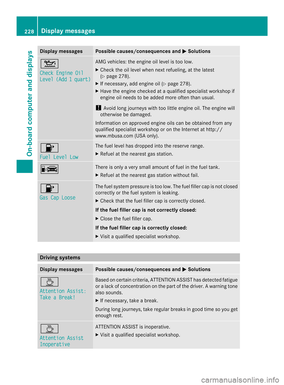
Display messages Possible causes/consequences and
0001 Solutions
0015
Check Engine Oil
Level (Add 1 quart) AMG vehicles: the engine oil level is too low.
X
Chec kthe oil level when next refueling, at the latest
(Y page 278).
X If necessary, add engine oil (Y page 278).
X Have the engine checked at a qualified specialist workshop if
engine oil needs to be added more often than usual.
! Avoid long journeys with too little engine oil. The engine will
otherwise be damaged.
Information on approved engine oils can be obtained from any
qualified specialist workshop or on the Internet at http://
www.mbusa.com (USA only). 0013
Fuel Level Low The fuel level has dropped into the reserve range.
X
Refuel at the nearest gas station. 000C There is only a very small amount of fuel in the fuel tank.
X
Refuel at the nearest gas station without fail. 0013
Gas Cap Loose The fuel system pressure is too low. The fuel filler cap is not closed
correctly or the fuel system is leaking.
X
Check that the fuel filler cap is correctly closed.
If the fuel filler cap is not correctly closed:
X Close the fuel filler cap.
If the fuel filler cap is correctly closed:
X Visit a qualified specialist workshop. Driving systems
Display messages Possible causes/consequences and
0001 Solutions
0002
Attention Assist:
Take a Break! Based on certain criteria, ATTENTION ASSIST has detected fatigue
or
alack of concentration on th epart of th edriver. A warning tone
also sounds.
X If necessary, take a break.
During long journeys, take regular breaks in good time so you get
enough rest. 0002
Attention Assist
Inoperative ATTENTION ASSIST is inoperative.
X
Visi taqualified specialist workshop. 228
Display messagesOn-board computer and displays
Page 252 of 358
Engine
Problem Possible causes/consequences and
0001 Solutions
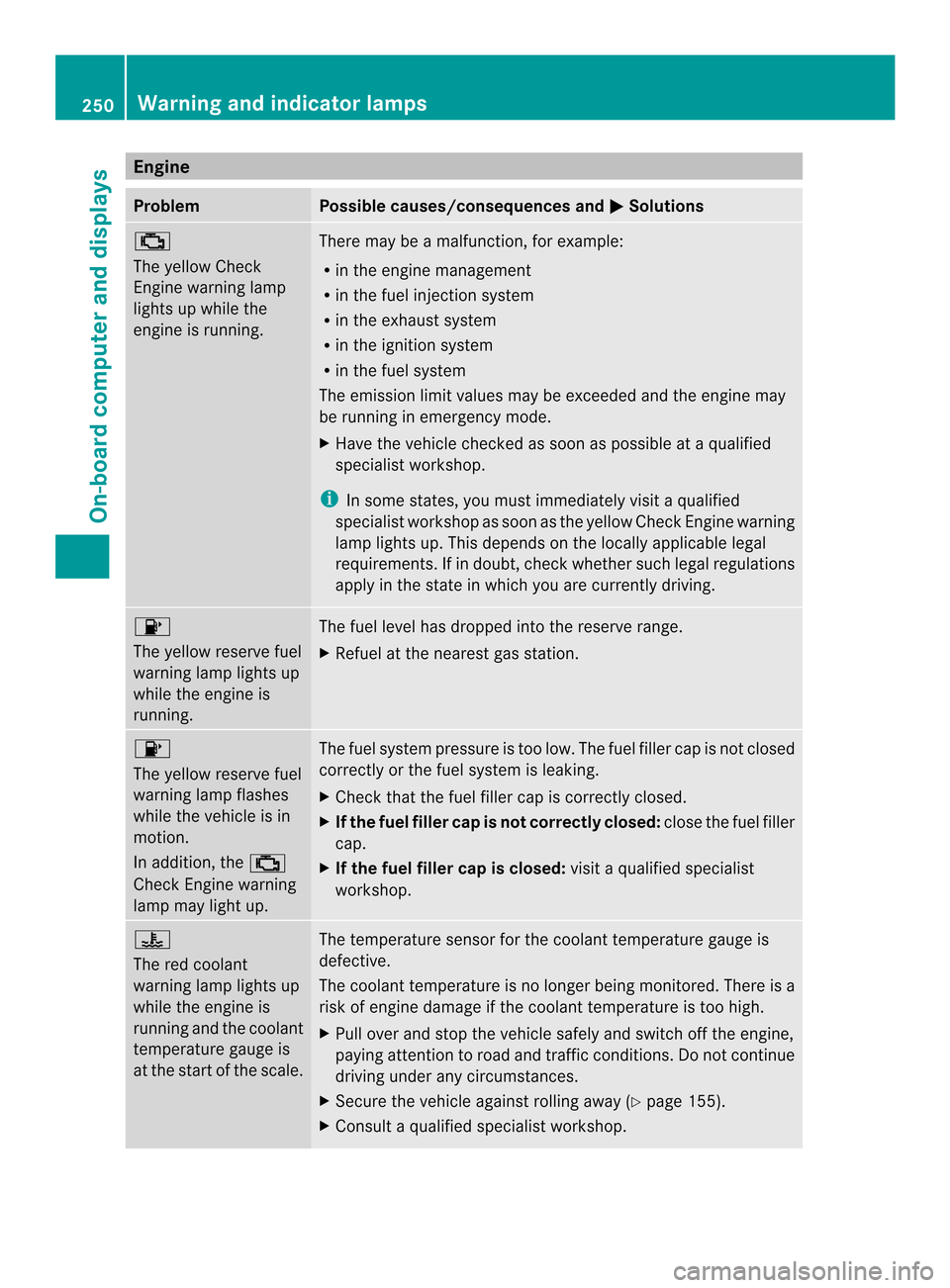
0011
The yellow Check
Engine warning lamp
lights up while the
engine is running. There may be a malfunction, for example:
R
in the engine management
R in the fuel injection system
R in the exhaust system
R in the ignition system
R in the fuel system
The emission limit values may be exceeded and the engin emay
be running in emergency mode.
X Have the vehicle checked as soon as possible at a qualified
specialist workshop.
i In some states, you must immediately visit a qualified
specialist workshop as soon as the yellow Chec kEngine warning
lamp lights up .This depends on the locally applicable legal
requirements. If in doubt, check whether such legal regulations
apply in the state in which you are currently driving. 0013
The yellow reserve fuel
warning lamp lights up
while the engine is
running. The fuel level has dropped into the reserve range.
X
Refuel at the nearest gas station. 0013
The yellow reserve fuel
warning lamp flashes
while the vehicle is in
motion.
In addition, the 0011
Check Engine warning
lamp may light up. The fuel system pressure is too low. The fuel filler cap is not closed
correctly or the fuel system is leaking.
X
Check that the fuel filler cap is correctly closed.
X If the fuel filler cap is not correctly closed: close the fuel filler
cap.
X If the fuel filler cap is closed: visit a qualified specialist
workshop. 000F
The red coolant
warning lamp lights up
while the engine is
running and the coolant
temperature gauge is
at the start of the scale. The temperature sensor for the coolant temperature gauge is
defective.
The coolant temperature is no longer being monitored. There is a
risk of engine damage if the coolant temperature is too high.
X
Pull over and stop the vehicle safely and switch off the engine,
paying attention to road and traffic conditions. Do not continue
driving under any circumstances.
X Secure the vehicle against rolling away (Y page 155).
X Consult a qualified specialist workshop. 250
Warning and indicator lampsOn-board computer and displays
Page 297 of 358
Do not continue driving. Contact a qualified
specialis
tworkshop.
Tire pressure of 180 kPa (1.8 bar/
26 psi) is reached G
WARNING
At ire temporarily sealed with tire sealant
impairs the driving characteristics and is not
suitable for higher speeds. There is a risk of
accident.
You should therefore adapt your driving style
accordingly and drive carefully. Do not exceed
the specified maximum speed with a tire that
has been repaired using tire sealant.
! Residue fro mthe tire sealant may come
out of the filler hose after use. This could
cause stains.
Therefore, place the filler hose in the plastic
bag which contained the TIREFIT kit. H
Environmental note
Have the used tire sealant bottle disposed of
professionally, e.g. at aqualified specialist
workshop.
If ap ressure of 200 kPa (2.0 ba r/29 psi) has
been attained after a maximum of ten
minutes:
X Switch off the tire inflation compressor.
X Unscrew the filler hose from the valve of
the faulty tire.
X Stow the tire sealant bottle and the tire
inflation compressor.
X Pull away immediately.
The maximu mspeed for a tire sealed with
tire sealant is 50 mph (80 km/h). The upper
part of the TIREFIT sticker must be affixed
to the instrument cluster in the driver's
field of vision.
X Stop after driving for approximately ten
minutes and chec kthe tire pressure with
the tire inflation compressor.
The tire pressure must now be at least
130 kPa (1.3 bar/19 psi). G
WARNING
If the required tire pressure is not reached
after driving for a short period, the tire is too
badly damaged. The tire sealant cannot repair
the tire in this instance. Damaged tires and a
tire pressure that is too low can significantly
impair the vehicle's braking and driving
characteristics. There is a risk of accident.
Do not continue driving. Contact a qualified
specialist workshop.
X Correct the tire pressure if it is still at least
130 kPa (1.3 bar/19 psi) (for the values,
see the Tire and Loading Information
placard on the B-pillar on the driver's side
or tire pressure table on the fuel filler flap).
X To increase the tire pressure: switch on
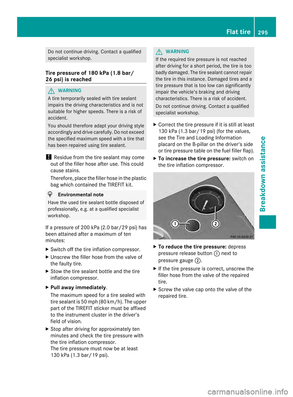
the tire inflation compressor. X
To reduce the tire pressure: depress
pressure release button 0003next to
pressure gauge 0004.
X If the tire pressure is correct, unscrew the
filler hose from the valve of the repaired
tire.
X Screw the valve cap onto the valve of the
repaired tire. Flat tire
295Breakdown assistance Z
Page 317 of 358
Information on air pressure for the tires on
yourv ehicle can be found:
R on the vehicle's Tire and Loading
Information placard on the B-pillar
(Y page 319)
R on the tire pressure label on the fuel filler
flap (Y page 153)
R in the "Tire pressure" section
Checking tire pressures manually To determine and set the correct tire
pressure, proceed as follows:
X Remove the valve cap of the tire that is to
be checked.
X Press the tire pressure gauge securely onto
the valve.
X Read the tire pressure and compare it with
the recommended value on the Tire and
Loading Information placard (Y page 311).
X If the tire pressure is too low, increase it to
the recommended value.
X If the tire pressure is too high, release air
by pressing down the metal pin in the valve.
Use the tip of a pen, for example. Then,
chec kthe tire pressure again using the tire
pressure gauge.
X Screw the valve cap onto the valve.
X Repeatt hese steps for the other tires. Tire pressure loss warning system
(Canada only)
Important safety notes While the vehicle is in motion, the tire
pressure loss warning system monitors the
set tire pressure using the rotational speed of
the wheels. This enables the system to detect
significant pressure loss in a tire. If the speed
of rotation of a wheel changes as a result of
a loss of pressure, a corresponding warning
message will appearint he multifunction
display. The tire pressure warning system does not
warn you of an incorrectly set tire pressure.
Observe the notes on the recommended tire
pressure (Y
page 311).
The tire pressure loss warning system does
not replace the need to regularly check your
vehicle's tire pressures, since an even loss of
pressure on several tires at the same time
cannot be detected by the tire pressure loss
warning system.
The tire pressure monitor is not able to warn
you of a sudden loss of pressure, e.g. if the
tire is penetrated by a foreign object. In the
event of a sudden loss of pressure, bring the
vehicle to a halt by braking carefully. Avoid
abrupt steering maneuvers.
The function of the tire pressure loss warning
system is limited or delayed if:
R snow chains are mounted to your vehicle's
tires.
R road conditions are wintry.
R you are driving on sand or gravel.
R you adopt a very sporty driving style
(cornering at high speeds or driving with
high rates of acceleration).
R you drive with a heavy load.
Restarting the tire pressure loss
warning system Restart the tire pressure loss warning system
if you have:
R
changed the tire pressure
R changed the wheels or tires
R mounted new wheels or tires
X Before restarting, make sure that the tire
pressures are set properly on all four tires
for the respective operating conditions.
The recommended tire pressures can be
found on the Tire and Loading Information
placard on the B-pillar on the driver's side
or the tire pressure table on the fuel filler
flap. Tire pressure
315Wheels and tires Z
Page 330 of 358
various operating conditions, i.e. differing
load and speed conditions.
Increased vehicle weight due to optional
equipment
This is the combined weight of all standard
and optional equipment available for the
vehicle, regardless of whethe
ritis actually
installed on the vehicle or not.
Rim
This is the part of the wheel on which the tire
is mounted.
GAWR (Gross Axle Weight Rating)
The GAWR is the maximum permissible axle
weight. The actual load on an axle must never
exceed the gross axle weight rating. The
gross axle weight rating can be found on the
vehicle identification plate on the B-pillar on
the driver's side.
Speed rating
The speed rating is part of the tire
identification. It specifies the speed range for
which the tire is approved.
GVW (Gross Vehicle Weight)
The gross vehicle weight includes the weight
of the vehicle including fuel, tools, the spare
wheel, accessories installed, occupants,
luggage and the drawbarn oseweight, if
applicable. The gross vehicle weight must not
exceed the gross vehicle weight rating GVWR
as specified on the vehicle identification plate
on the Bpillar on the driver's side.
GVWR (Gross Vehicle Weight Rating)
The GVWR is the maximum permissible gross
weight of a fully loaded vehicle (the weight of
the vehicle including all accessories,
occupants, fuel, luggage and the drawbar
noseweight, if applicable). The gross vehicle
weight rating is specified on the vehicle
identification plate on the B-pillar on the
driver's side. Maximu
mloaded vehicle weight
The maximum weight is the sum of:
R the curb weight of the vehicle
R the weight of the accessories
R the load limit
R the weight of the factory installed optional
equipment
Kilopascal (kPa)
Metric unit for tire pressure. 6.9 kPa
corresponds to 1 psi. Another unit for tire
pressure is bar. There are 10 0kilopascals
(kPa) to 1bar.
Load index
In addition to the load-bearing index, the load
index may also be imprinted on the sidewall
of the tire. This specifie sthe load-bearing
capacity more precisely.
Curb weight
The weight of a vehicle with standard
equipment including the maximum capacity
of fuel, oil and coolant. It also includes the air-
conditioning system and optional equipment
if these are installed in the vehicle, but does
not include passengers or luggage.
Maximum load rating
The maximum tire load is the maximum
permissible weight in kilograms or lbs for
which a tire is approved.
Maximum permissible tire pressure
Maximum permissible tire pressure for one
tire.
Maximum load on one tire
Maximum load on one tire. This is calculated
by dividing the maximum axle load of one axle
by two.
PSI (pounds per square inch)
As tandard uni tofmeasure for tire pressure. 328
All about wheels and tiresWheels and tires