service indicator MERCEDES-BENZ SLK-Class 2013 R172 Owner's Manual
[x] Cancel search | Manufacturer: MERCEDES-BENZ, Model Year: 2013, Model line: SLK-Class, Model: MERCEDES-BENZ SLK-Class 2013 R172Pages: 358, PDF Size: 4.61 MB
Page 6 of 358
1, 2, 3 ...
12 Vsocket
see Sockets A
ABS (Anti-lock Braking System) Display message ............................ 212
Function/notes ................................ 59
Important safety notes ....................59
Warning lamp ................................. 244
Activating/deactivating cooling
with air dehumidification .................125
Active light function .........................110
ADAPTIVE BRAKE ................................. 65
Adaptive Highbeam Assist Display message ............................ 225
Function/notes ............................. 110
Switching on/off (on-board
computer) ...................................... 204
Additional speedometer ...................204
Additives (engine oil) ........................351
Airb ags
Display message ............................ 221
Front air bag (driver, front
passenger )....................................... 42
Head bag ......................................... 44
Important safety notes ....................41
Knee bag .......................................... 43
PASSENGER AIR BAG OFF
indicator lamp .................................. 45
Safety guidelines ............................. 40
Side impact airb ag.......................... 43
Air-conditioning system
see Climate control
AIRGUIDE ............................................. 90
AIRSCARF Problem (malfunction) .....................98
Setting the vents ........................... 131
Switching on/off .............................. 98
Airv ents
Important safet ynotes .................. 130
Setting ........................................... 130
Setting the AIRSCARF vents ..........131
Setting the center air vents ...........130
Setting the side air vents ...............130
Switching AIRSCARF on/off ............98Alarm system
see ATA (Anti-Theft Alarm system)
Ambient lighting
Setting the brightness (on-board
computer) ...................................... 204
Setting the color (on-board
computer) ...................................... 205
AMG menu (on-board computer) .....207
Anti-loc kbraking system
see ABS (Anti-lock Braking System)
Anti-theft alarm system
see ATA (Anti-Theft Alarm system)
Ashtray ............................................... 260
Assistance menu (on-board
computer) .......................................... 201
ASSYST PLUS Displaying a service message ........280
Hiding a service message ..............280
Resetting the service interval
displa y........................................... 280
Service message ............................ 280
Special service requirements ......... 281
ATA (Anti-Theft Alarm system)
Activating/deactivating ...................67
Function .......................................... .67
Switching off the alarm ....................67
ATTENTIO NASSIST
Activating/deactivating .................202
Display message ............................ 228
Function/notes ............................. 184
Audio menu (on-board computer) ....199
Authorized Centers see Qualified specialist workshop
Authorized Mercedes-Benz Center
see Qualified specialist workshop
Authorized workshops
see Qualified specialist workshop
AUTO lights
Display message ............................ 225
see Lights
Automatic engine start (ECO start/
stop function) .................................... 141
Automatic engine switch-off (ECO
start/stop function) ..........................141
Automatic headlamp mode ..............107 4
Index
Page 15 of 358
On-board computer
AMG menu .................................... .207
Assistance menu ........................... 201
Audi omenu ................................... 199
Convenience submenu ..................206
Displaying a service message ........280
Display messages ..........................211
DISTRONI CPLUS ........................... 173
Factory settings submenu .............203
Important safety notes ..................192
Instrument cluster submenu ..........203
Lighting submenu .......................... 204
Menu overview .............................. 195
Message memory .......................... 211
Navigation menu ............................ 197
Operation ....................................... 194
RACETIMER ................................... 208
Service menu ................................. 203
Settings menu ............................... 203
Standard displa y............................ 196
Telephone menu ............................ 200
Trip menu ...................................... 196
Vehicle submenu ........................... 206
Video DVD operatio n..................... 200
Operating system
see On-board computer
Outside temperature display ...........193
Overhead control panel ......................34 P
Pain tcode number ............................ 347
Paintwork (cleaning instructions) ...283
Panic alarm .......................................... 38
Parking ............................................... 155
Important safety notes ..................155
Parking brake ................................ 156
Position of exterior mirror, front-
passenger side ............................... 102
see PARKTRONIC
Parking aid
Parking Guidance ........................... 181
see Exterior mirrors
see PARKTRONIC
Parking brake
Display message ............................ 214
Electric parking brake ....................156
Warning lamp ................................. 249 Parking Guidance
Display message ............................ 230
Important safety notes ..................181
Parking lamps
Switching on/off ........................... 108
PARKTRONIC
Deactivating/activating .................180
Driving system ............................... 178
Function/notes ............................. 178
Important safety notes ..................178
Problem (malfunction) ...................181
Range of the sensors .....................179
Warning displa y............................. 179
PASSENGE RAIR BAG OFF indicator
lamp ...................................................... 45
Pivoting draf tstop
see AIRGUIDE
Plastic trim (cleaning instructions) .286
Power washers .................................. 283
Power windows see Side windows
PRE-SAFE ®
(anticipatory occupant
protection) Display message ............................ 218
Operation ........................................ .50
PRE-SAFE ®
Brake
Activating/deactivating .................202
Display message ............................ 218
Function/notes ................................ 65
Warning lamp ................................. 252
Product information ............................20
Program selector button ..................147
Pulling away Automatic transmission .................138
Manual transmission ..................... .138 Q
Qualifie dspecialis tworkshop ...........23 R
RACETIMER (on-board computer) ....208
Radar sensor system Activating/deactivating .................206
Display message ............................ 229
Radio
Selecting astation ......................... 199 Index
13
Page 69 of 358
The immobilizer prevents your vehicle from
being started without the correct SmartKey.
When leaving the vehicle, always take the
SmartKey with you and lock the vehicle. The
engine can be started by anyone with a valid
SmartKey that is left inside the vehicle.
i The immobilizer is always deactivated
when you start the engine.
In the event that the engine cannot be
started when the starter battery is fully
charged, the immobilizer may be faulty.
Contact an authorized Mercedes-Benz
Center or call 1-800-FOR-MERCedes (in
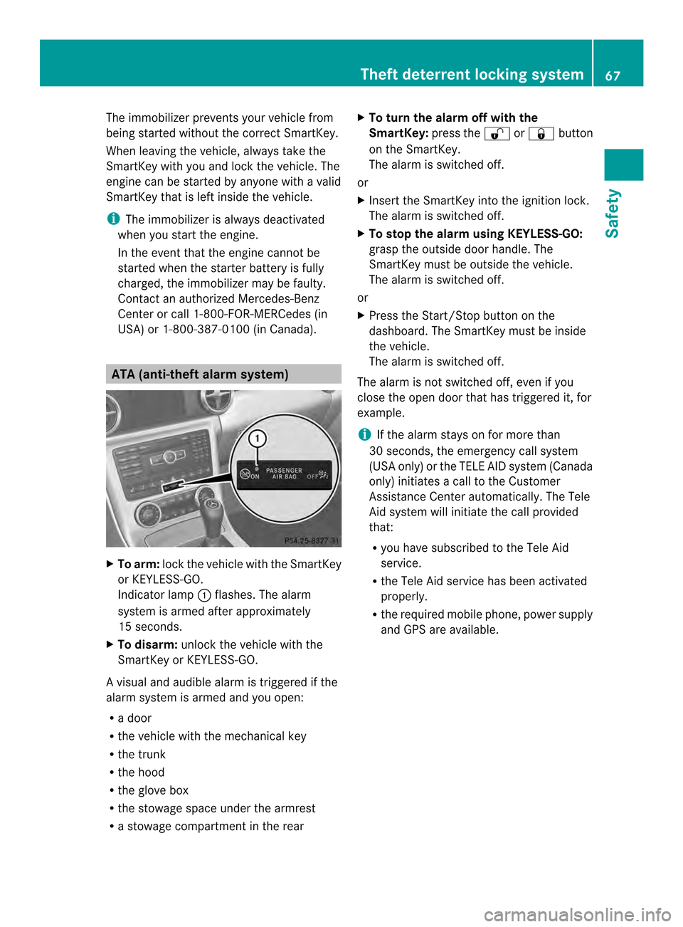
USA) or 1-800-387-0100 (in Canada). ATA (anti-theft alarm system)
X
To arm: lock the vehicle with the SmartKey
or KEYLESS-GO.
Indicator lamp 0003flashes. The alarm
system is armed after approximately
15 seconds.
X To disarm: unlock the vehicle with the
SmartKey or KEYLESS-GO.
Av isual and audible alarm is triggered if the
alarm system is armed and you open:
R a door
R the vehicle with the mechanical key
R the trunk
R the hood
R the glove box
R the stowage space under the armrest
R a stowage compartmen tinthe rear X
To turn the alarm off with the
SmartKey: press the0010or000F button
on the SmartKey.
The alarm is switched off.
or
X Insert the SmartKey into the ignition lock.
The alarm is switched off.
X To stop the alarm using KEYLESS-GO:
grasp the outside door handle. The
SmartKey must be outside the vehicle.
The alarm is switched off.
or
X Press the Start/Stop button on the
dashboard. The SmartKey must be inside
the vehicle.
The alarm is switched off.
The alarm is not switched off, even if you
close the open door that has triggered it, for
example.
i If the alarm stays on for more than
30 seconds, the emergency call system
(USA only) or the TELE AID system (Canada
only) initiates a call to the Customer
Assistance Center automatically .The Tele
Aid system will initiate the call provided
that:
R you have subscribed to the Tele Aid
service.
R the Tele Aid service has been activated
properly.
R the required mobile phone, power supply
and GPS are available. Theft deterrent locking system
67Safety Z
Page 267 of 358
Please also read the operating instructions
for the garage door system.
X Turn the SmartKey to position 2in the
ignition lock.
X Press button 0004,0024or0023 which you have
programmed to operate the garage door.
Garage door system with a fixed code:
indicator lamp 0003lights up green.
Garage door system with a rolling code:
indicator lamp 0003flashes green.
i The transmitter will transmit a signal as
long as the button is pressed. The
transmission is halted after a maximum of
ten seconds and indicator lamp 0003lights
up yellow. Press button 0004,0024or0023 again
if necessary.
Clearing the memory X
Turn the SmartKey to position 2in the
ignition lock.
X Press buttons 0004and 0023.
The indicator lamp lights up yellow.
X Press and hold buttons 0004and 0023until the
indicator lamp turns green.
i Make sure that you clear the memory of
the integrated garage door opener before
selling the vehicle. mbrace
Important safety notes !
Alicense agreement must exis tinorder
to activate the mbrace service. Ensure that
yours ystem is activated and ready fo ruse,
and press the 0008MB Info call button to
register. If any of the steps mentioned is
not carried out, the system may not be
activated.
If you have questions aboutt he activation,
contact one of the following telephone
assistance services:
R USA: Mercedes-Ben zCustomer
Assistance Cente runder 1-800-FOR-MERCedes
(1-800-367-6372) or 1-888-990-9007
R Canada: Customer Service at
1-888-923-8367
Shortly after successfull yregistering with the
mbrace service (Canada: TELEAID), a user ID
and password will be sent to you by post. USA
only: you can use this password to log onto
the mbrace area under "Owners Online" at
http://www.mbusa.com.
The mbrace system is available if:
R it has been activated and is operational
R the corresponding mobile phone network
is available for transmitting data to the
Customer Center
R a service subscription is available
R the starter battery is sufficiently charged
i Determining the location of the vehicle on
a map is only possible if:
R GPS reception is available
R the vehicle position can be forwarded to
the Customer Assistance Center
The mbrace system To adjust the volume during an mbrace call,
proceed as follows:
X
Press the 0009or000A button on the
multifunction steering wheel.
or
X Use the volume controller of the audio
system/COMAND.
The mbrace system provides various
services, e.g.:
R automatic and manual emergency call
R Roadside Assistance call
R MB Info call
USA only: you can find information and a
description of all available features under
"Owners Online" at http://www.mbusa.com. Features
265Stowage and features Z
Page 268 of 358
System self-test
After you have switched on the ignition, the
system carries out a self-diagnosis.
Am
alfunction in the system has been
detected if one of the following conditions
occurs:
R the indicator lamp in th eSOS button does
not come on during the system self-test.
R the indicator lamp in the 0006Roadside
Assistance button does not light up during
self-diagnosis of the system.
R the indicator lamp in the 0008MB-Info call
button does not light up during self-
diagnosis of the system.
R the indicator lamp in one or more of the
following buttons continues to light up red
after the system self-diagnosis:
-SOS button
- Roadside Assistance call button 0006
- MB Info call button 0008
R The mbrace Inoperative or
mbrace Service Not Activated message
appears in the multifunction display after
the system self-diagnosis.
If a malfunction is indicated as outlined
above, the system may not operate as
expected. In the event of an emergency,
assistance must be summoned by other
means.
Have the system checked at the nearest
authorized Mercedes-Benz Center or contact
the following service hotlines:
R USA: Mercedes-Benz Customer Assistance
center at
1-800-FOR-MERCedes (1-800-367-6372)
or 1-888-990-9007
R Canada: Customer Service at
1-888-923-8367 Emergency call Important safety notes
G
WARNING
If the indicator lamp in the SOS button is
flashing continuously and no voice
connection with the Response center has
been established, then the mbrace system
has not been able to initiate an emergency call
(e.g. the relevant mobile phone network is not
available).
The Call Failed message is displayed in the
multifunction display and must be confirmed.
Should this occur, assistance must be
summoned by other means.
! Alicense agreement must exis tinorder
to activate the mbrace service. Ensure that
yours ystem is activated and ready fo ruse,
and press the 0008MB Info call button to
register. If any of the steps mentioned is
not carried out, the system may not be
activated.
If you have questions aboutt he activation,
contact one of the following telephone
assistance services:
R USA: Mercedes-Ben zCustomer
Assistance Cente runder
1-800-FOR-MERCedes
(1-800-367-6372) or 1-888-990-9007
R Canada: Customer Service at
1-888-923-8367
An emergency call is dialed automatically if
an ai rbag or Emergency Tensioning Device is
triggered.
i You canno tend an automatically
triggered emergency call yourself.
An emergency call can also be initiated
manually.
As soo nas the emergency call has been
initiated, the indicator lamp in the SOS button
flashes. The Connecting Call message
appears on the multifunction display.
The audio output is muted. 266
FeaturesStowage and features
Page 270 of 358

the navigation menu by pressing the NAVI
button on COMAND, for example.
Voice outpu
tis not available.
Av oice connection is established between
the Mercedes-Benz Customer Assistance
Center and the vehicle occupants.
From the vehicle remote malfunction
diagnosis, the Mercedes-Benz Customer
Assistance center can ascertain the nature of
the problem (Y page 271).
The Mercedes-Benz Customer Assistance
Center either sends a qualified Mercedes-
Benz technician or organizes for your vehicle
to be transported to the nearest authorized
Mercedes-Benz Center. You may be charged
for services such as repair work and/or
towing. Further details are available in your
mbrace manual.
i The mbrace system failed to initiate a
Roadside Assistance call if:
R the indicator lamp for Roadside
Assistance call button 0003is flashing
continuously
R no voice connection to the Mercedes-
Benz Customer Assistance Center was
established
This may be because the corresponding
mobile phone network is not available.
The Call Failed message appears in the
multifunction display.
X To end acall: press the 000Cbutton on the
multifunctio nsteering wheel.
or
X Press the corresponding button for ending
a phone call on the audio syste moron
COMAND. MB Info call button X
Press MB Info call button 0003.
This initiates a call to the Mercedes-Benz
Custome rAssistance Center. The indicator
lamp in MB Info call button 0003flashes while
the connection is being made. The
Connecting Call message appears on
the multifunction display. The audio system
is muted.
If a connection can be made, the Call Connected message appears in the
multifunction display.
If a cellular phone network is available and
there is sufficient GPS reception, the mbrace
system transmits data to the Mercedes-Benz
Customer Assistance Center, for example:
R current location of the vehicle
R vehicle identification number
i The display of the audio system or
COMAND shows that an mbrace call is
active. During the call, you can change to
the navigation menu by pressing the NAVI
button on COMAND, for example.
Voice output is not available.
Av oice connection is established between
the Mercedes-Benz Customer Assistance
Center and the vehicle occupants. You can
obtain information on how to operate your
vehicle's systems, on the location of the
nearest authorized Mercedes-Benz Center,
and on further products and services offered
by Mercedes-Benz USA. 268
FeaturesStowage and features
Page 271 of 358
USA only: you can find further information on
the mbrace system under "Owners Online" at
http://www.mbusa.com.
i The mbrace system failed to initiate an
MB Info call if:
R the indicator lamp in MB Info call
button 0003is flashing continuously
R no voice connection to the Mercedes-
Benz Customer Assistance Center was
established
This may be because the corresponding
mobile phone network is not available.
The Call Failed message appears in the
multifunction display.
X To end acall: press the 000Cbutton on the
multifunctio nsteering wheel.
or
X Press the corresponding button for ending
a phone call on the audio syste moron
COMAND.
Call priority When service calls are active, e.g. Roadside
Assistance or MB Info calls, an emergency
call can still be initiated. In this case, an
emergency call will take priority and override
all other active calls.
The indicator lamp of the respective button
flashes until the call is ended. An emergency
call can only be terminated by the Mercedes-
Benz Customer Assistance Center.
All other calls can be ended by pressing:
R the 000C button on the multifunction
steering wheel
R the corresponding butto nonthe audio
system or on COMAND to end the voice call
i If an mbrace call is initiated, audio output
is muted. The mobile phone is no longer
connected to COMAND. However, if you
want to use your mobile phone, do so only
when the vehicle is stationary and in a safe
location. Downloading destinations in COMAND Downloading destinations
Downloading destinations gives you access
to a data bank with over 15 million Points of
Interest (POIs). These can be downloaded on
the navigation system in your vehicle. If you
know the destination, the address can be
downloaded.A
lternatively, you can obtain the
location of Points of Interest (POIs)/
importan tdestinations in the vicinity.
Furthermore, you can download routes with
up to 20 way points.
You are prompted to confirm route guidance
to the address entered.
X Select Yes with the
0002or0005 buttons
on the COMAND system.
X Confirm with the 0003button on the
COMAND system.
The system calculates the route and
subsequently starts the route guidance with
the address entered.
i If you select No , the address can be stored
in the address book.
i The Destination Download function is
available if the correspondin gmobile
phone network is available and data
transfer is possible.
i You can only use the Destination
Download function if the vehicle is
equipped with a navigation system.
Route Assistance
This service is part of the mbrace PLUS
Package and cannot be purchased
separately.
i You can also use the Route Assistance
function if your vehicle is not equipped with
a navigation system.
Within the framework of this service, you
receive a professional and reliable form of
navigation support without having to leave
your vehicle. Features
269Stowage and features Z
Page 299 of 358
G
WARNING
Failure to follow these instructions can result
in severe injury or death.
Never leano ver batteries while connecting.
You might get injured.
Battery fluid contains sulfuric acid. Do not
allow this fluid to come in contact with eyes,
skin or clothing. In case it does, immediately
flush affected area with water and seek
medical help if necessary.
Ab attery will also produce hydrogen gas,
which is flammable and explosive. Keep
flames or sparks away from battery, avoid
improper connection of jumper cables,
smoking etc. G
WARNING
Do no tplace any metal objects on the battery
as this could result in a shor tcircuit.
Use leak-proof batteries only to avoid the risk
of acid burns in the event of an accident.
Take care that you do not become statically
charged, e.g. by wearin gsynthetic clothing or
rubbing against textiles .For this reason, you
also should not pull or push the battery over
carpets or other synthetic materials.
Never touch the battery first. First, touch the
outside body of the vehicle in order to release
any possible electrostatic charges.
Do not rub the battery with rags or cloths. The
battery could explode if touched due to
electrostatic charge or due to spark
formation. H
Environmental note Batteries contain dangerous
substances. It is against the
law to dispose of them with
the household rubbish. They
must be collected separately
and recycled to protect the
environment.
Dispose of batteries in an
environmentally friendly
manner
.Take discharged batteries to a qualified
specialist workshop or a
special collectio
npoint for
used batteries.
! Have the battery checked regularly at a
qualified specialist workshop.
Observe the service intervals in the
Maintenance Booklet or contact a qualified
specialist workshop for more information.
! You should have all work involving the
battery carried out at aqualified specialist
workshop. In the exceptional case that it is
necessary for you to disconnect the battery
yourself, make sure that:
R you switch off the engine and remove the
key. On vehicles with KEYLESS-GO,
ensure that the ignition is switched off.
Chec kthat all the indicator lamps in the
instrument cluster are off. Otherwise,
electronic components, such as the
alternator, may be damaged.
R you first remove the negative terminal
clamp and then the positive terminal
clamp. Never swap the terminal clamps.
Otherwise, the vehicle's electronic
system may be damaged.
R in vehicles with automatic transmission,
the transmission is locked in position P
after disconnecting the battery. The
vehicle is secured against rolling away.
You can then no longer move the vehicle.
The battery and the cover of the positive
terminal clamp must be installed securely
during operation.
In order for the battery to achieve the
maximum possible service life, it must always
be sufficiently charged.
The vehicle battery, like other batteries, can
discharge over time if you do not use the
vehicle. In this case, have the battery
disconnected at a qualified specialist
workshop. You can also charge the battery
with a charger recommended by Mercedes- Battery (vehicle)
297Breakdown assistance Z
Page 311 of 358

Regular checking of wheels and tires
G
WARNING
Damaged tires can cause tire inflation
pressure loss. As a result, you could lose
control of your vehicle. There is a ris kof
accident.
Chec kthe tires regularly for signs of damage
and replace any damaged tires immediately.
Regularly check the wheels and tires of your
vehicle for damage at least once a month, as
well as after driving off-road or on rough
roads. Damaged wheels can cause a loss of
tire pressure. Pay particular attention to
damage such as:
R cuts in the tires
R punctures
R tears in the tires
R bulges on tires
R deformation or severe corrosion on wheels
Regularly check the tire tread depth and the
condition of the tread across the whole width
of the tire (Y page 309). If necessary, turn
the front wheels to full lock in order to inspect
the inner side of the tire surface.
All wheels must have a valve cap to protect
the valve against dirt and moisture. Do not
mount anything onto the valve other than the
standard valve cap or other valve caps
approved by Mercedes-Ben zfor your vehicle.
Do not use any other valve caps or systems,
e.g. tire pressure monitoring systems.
Regularly check the pressure of all the tires
particularly prior to long trips. Adjust the tire
pressure as necessary (Y page 311).
Observe the notes on the emergency spare
wheel (Y page 339).
The service life of tires depends on the
following factors amongst other things:
R Driving style
R Tire pressure
R Distance covered Tire tread
G
WARNING
Insufficient tire tread will reduce tire traction.
The tire is no longer able to dissipate water.
This means that on wet road surfaces, the risk
of hydroplaning increases, in particular where
speed is not adapted to suit the driving
conditions. There is a risk of accident.
If the tire pressure is too high or too low, tires
may exhibit different levels of wear at
different locations on the tire tread. Thus, you
should regularly check the tread depth and
the condition of the tread across the entire
width of all tires.
Minimum tire tread depth for:
R Summer tires: 000Ain (3 mm)
R M+S tires: 000Bin (4 mm)
For safety reasons, replace the tires before
the legally prescribed limit for the minimum
tire tread depth is reached. Bar indicator
0003for tread wear is integrated
into the tire tread.
Tread wear indicators (TWI) are required by
law. Six indicators are positioned on the tire
tread. They are visible once the tread depth
is approximately 0009in (1.6 mm). If this is the
case, the tire is so worn that it must be
replaced. Operation
309Wheels and tires Z