check oil MERCEDES-BENZ SLK-Class 2015 R172 Owner's Manual
[x] Cancel search | Manufacturer: MERCEDES-BENZ, Model Year: 2015, Model line: SLK-Class, Model: MERCEDES-BENZ SLK-Class 2015 R172Pages: 358, PDF Size: 6.18 MB
Page 11 of 358
ECO start/stop function
Automatic engine start .................. 146
Automatic engine switch-off .......... 144
Deactivating/activating ................ .147
General information ....................... 144
Important safety notes .................. 143
Introduction ................................... 143
Electronic Stability Program
see ESP ®
(Electronic Stability Program)
Emergency
Automatic measures after an acci-
dent ................................................. 57
Emergency release
Driver's door ................................... .80
Trunk ............................................... 83
Vehicle ............................................. 80
Emergency spare wheel
General notes ................................ 341
Important safety notes .................. 341
Removing ....................................... 341
Stowing .......................................... 342
Technical data ...............................3 44
Emergency Tensioning Devices
Activation ......................................... 54
Emissions control
Service and warranty information .... 22
Engine
Check Engine warning lamp ........... 251
Display message ............................ 228
ECO start/stop function ................ 143
Engine number ............................... 347
Irregular running ............................ 149
Jump-starting ................................. 301
Starting problems .......................... 149
Starting the engine with the
SmartKey ....................................... 142
Starting with KEYLESS-GO ............. 142
Switching off .................................. 162
Tow-starting (vehicle) ..................... 306
Engine electronics
Problem (malfunction) ................... 149
Engine oil
Adding .......................................... .280
Additives ........................................ 350
Checking the oil level ..................... 279
Checking the oil level using the
dipstick .......................................... 279 Display message ............................ 230
Filling capacity ............................... 350
Notes about oil grades ................... 349
Notes on oil level/consumption .... 279
Temperature (on-board com-
puter) ............................................. 208
Viscosity ........................................ 350
ESP ®
(Electronic Stability Pro-
gram) AMG menu (on-board computer) ... 209
Characteristics ................................. 64
Deactivating/activating (AMG
vehicles) .......................................... 65
Deactivating/activating (notes;
except AMG vehicles) ..................... .64
Display message ............................ 213
ETS .................................................. 63
Function/note s................................ 63
General notes .................................. 63
Important safety information ........... 64
Warning lamp ................................. 247
ETS (Electronic Traction System) ....... 63
Exhaust check ................................... 165
Exhaust pipe (cleaning instruc-
tions) .................................................. 287
Exterior lighting Setting options .............................. 108
see Lights
Exterior mirrors
Adjusting ....................................... 103
Dipping (automatic) ....................... 104
Folding in/out (automatically )....... 104
Folding in/out (electrically) ........... 104
Folding in when locking (on-board
computer) ...................................... 208
Out of position (troubleshooting) ... 104
Storing settings (memory func-
tion) ............................................... 106
Storing the parking position .......... 105
Eyeglasses compartment ................. 257 F
Filler cap see Fuel filler flap
Filling capacities (Technical data) ... 347
Flat tire MOExtended tire s.......................... 293 Index
9
Page 19 of 358
Technical data
Capacities ...................................... 347
Emergency spare wheel ................. 344
Information .................................... 346
Tires/wheels ................................. 337
Vehicle data ................................... 353
TELEAID
Call priority .................................... 265
Downloading destinations
(COMAND) ..................................... 266
Downloading routes ....................... 269
Emergency call .............................. 263
General notes ................................ 261
Geo fencing ................................... 269
Locating a stolen vehicle ............... 268
MB info call button ....................... .265
Remote vehicle locking .................. 267
Roadside Assistance button .......... 264
Search & Send ............................... 266
Self-test ......................................... 262
Speed alert ................................... .269
System .......................................... 262
Triggering the vehicle alarm ........... 270
Vehicle remote malfunction diag-
nosis .............................................. 268
Vehicle remote unlocking .............. 267
Telephone
Accepting a call ............................ .202
Display message ............................ 241
Menu (on-board computer) ............ 201
Number from the phone book ....... .202
Redialing ........................................ 202
Rejecting/ending a call ................. 202
Temperature
Coolant .......................................... 194
Coolant (on-board computer) ......... 208
Engine oil (on-board computer) ...... 208
Outside temperature ..................... .195
Setting (climate control) ................ 129
Time
see separate operating instructions
Timing (RACETIMER) ......................... 209
TIREFIT kit .......................................... 294
Tire pressure Calling up (on-board computer) ..... 318
Checking manually ........................ 317
Display message ............................ 236 Important safety notes .................. 318
Maximum ....................................... 316
Notes ............................................. 315
Not reached (TIREFIT) .................... 295
Reached (TIREFIT) .......................... 296
Recommended ............................... 314
Tire pressure loss warning sys-
tem
General notes ................................ 317
Important safety notes .................. 317
Restarting ...................................... 318
Tire pressure monitor
Radio type approval for the tire
pressure monitor ........................... 321
Tire pressure monitoring system
Checking the tire pressure elec-
tronically ........................................ 320
Function/notes ............................ .318
General notes ................................ 318
Important safety notes .................. 319
Restarting ...................................... 321
Warning lamp ................................. 254
Warning message .......................... 320
Tires
Aspect ratio (definition) ................. 331
Average weight of the vehicle
occupants (definition) .................... 330
Bar (definition) ............................... 330
Changing a wheel .......................... 332
Characteristics .............................. 329
Checking ........................................ 311
Curb weight (definition) ................. 331
Definition of terms ......................... 329
Direction of rotatio n...................... 332
Display message ............................ 236
Distribution of the vehicle occu-
pants (definition) ............................ 332
DOT, Tire Identification Number
(TIN) ............................................... 329
DOT (Department of Transporta-
tion) (definition) ............................. 330
GAWR (Gross Axle Weight Rating)
(definition) ..................................... 330
GVW (Gross Vehicle Weight) (def-
inition) ........................................... 330
GVWR (Gross Vehicle Weight Rat-
ing) (definition) .............................. 330
Important safety notes .................. 310 Index
17
Page 142 of 358
KEYLESS-GO
General notes
Vehicles with KEYLESS-GO are equipped with
a SmartKey featuring an integrated KEYLESS- GO start function and a detachable Start/
Stop button.
The Start/Stop button must be inserted in the
ignition lock and the SmartKey must be in the
vehicle.
When you insert the Start/Stop button into
the ignition lock, the system needs approx-
imately two seconds recognition time. You
can then use the Start/Stop button.
Pressing the Start/Stop button several times
in succession corresponds to the different
key positions in the ignition lock. This is only
the case if you are not depressing the brake
pedal.
If you depress the brake pedal and press the
Start/Stop button, the engine starts immedi-
ately.
A check which periodically establishes a radio connection between the vehicle and the
SmartKey determines whether a valid Smart-Key is in the vehicle. This occurs, for example,
when starting the engine.
To start the vehicle without actively using the
SmartKey:
R the Start/Stop button must be inserted in
the ignition lock.
R the SmartKey must be in the vehicle.
R the vehicle must not be locked with the
SmartKey or KEYLESS-GO (Y page 73).
Do not keep the SmartKey:
R with electronic devices, e.g. a mobile
phone or another SmartKey
R with metallic objects, e.g. coins or metal
foil
R inside metallic objects, e.g. a metal case
This can impair the functionality of the KEY-
LESS-GO key.
i The engine can be turned off while the
vehicle is in motion by pressing and holding the Start/Stop button for approximately
three seconds. This function operates inde-
pendently of the ECO start/stop automatic
engine switch-off function.
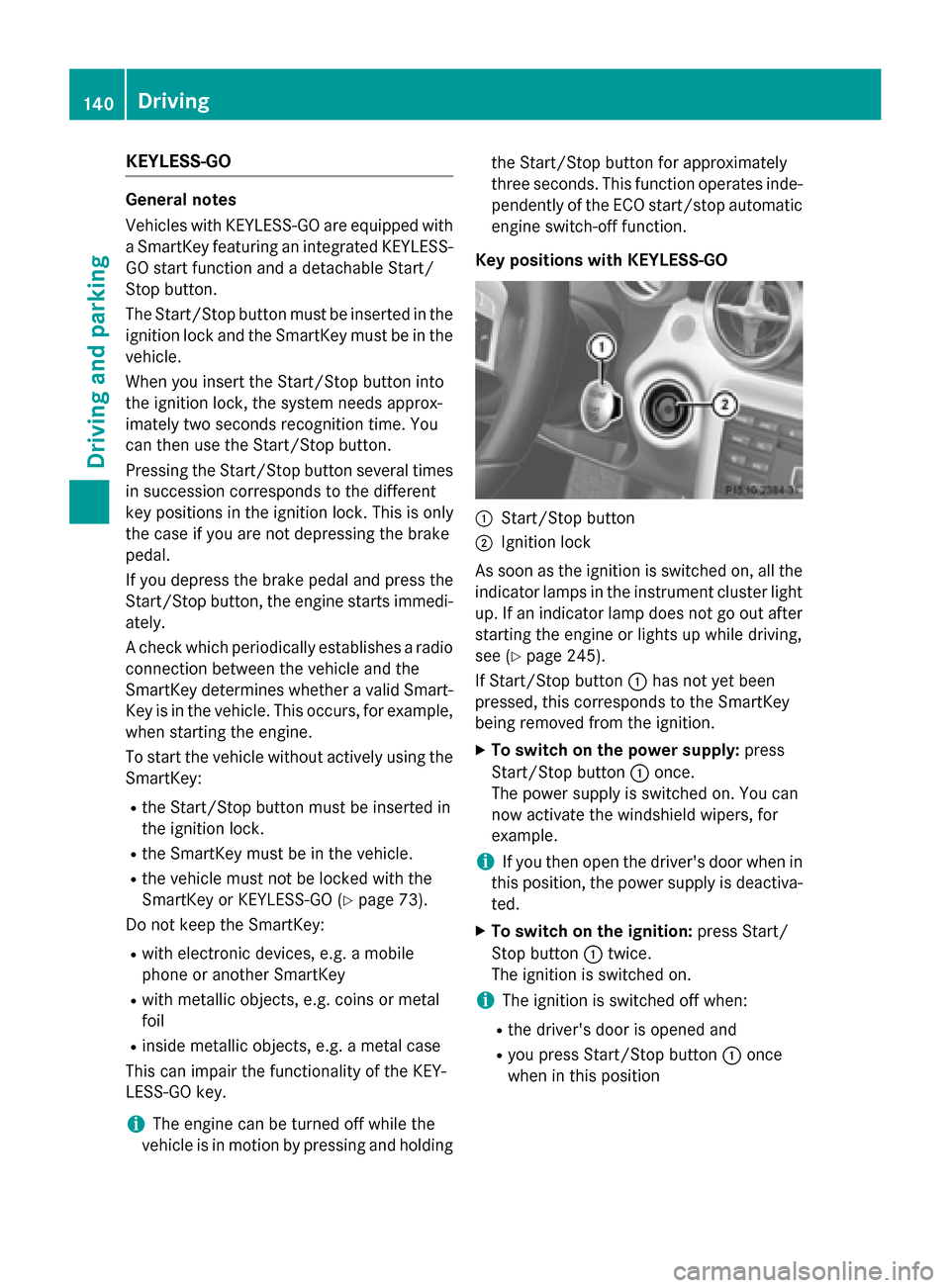
Key positions with KEYLESS-GO 0043
Start/Stop button
0044 Ignition lock
As soon as the ignition is switched on, all the
indicator lamps in the instrument cluster light up. If an indicator lamp does not go out afterstarting the engine or lights up while driving,
see (Y page 245).
If Start/Stop button 0043has not yet been
pressed, this corresponds to the SmartKey
being removed from the ignition.
X To switch on the power supply: press
Start/Stop button 0043once.
The power supply is switched on. You can
now activate the windshield wipers, for
example.
i If you then open the driver's door when in
this position, the power supply is deactiva-
ted.
X To switch on the ignition: press Start/
Stop button 0043twice.
The ignition is switched on.
i The ignition is switched off when:
R the driver's door is opened and
R you press Start/Stop button 0043once
when in this position 140
DrivingDriving and pa
rking
Page 160 of 358
Problems with the transmission
Problem
Possible causes/consequences and
0050
0050Solutions The transmission has
problems shifting gear. The transmission is losing oil.
X Have the transmission checked at a qualified specialist work-
shop immediately. The acceleration ability
is deteriorating.
The transmission no
longer changes gear. The transmission is in emergency mode.
It is only possible to shift into
secondgear and reverse gear.
X Stop the vehicle.
X Shift the transmission to position P.
X Switch off the engine.
X Wait at least ten seconds before restarting the engine.
X Shift the transmission to position Dor R.
If D is selected, the transmission shifts into secondgear; ifRis
selected, the transmission shifts into reverse gear.
X Have the transmission checked at a qualified specialist work-
shop, e.g. an authorized Mercedes-Benz Center, immediately. Releasing the parking lock manually
! Do not use any sharp-edged objects to
remove the selector lever gaiter from the
center console. This could damage the
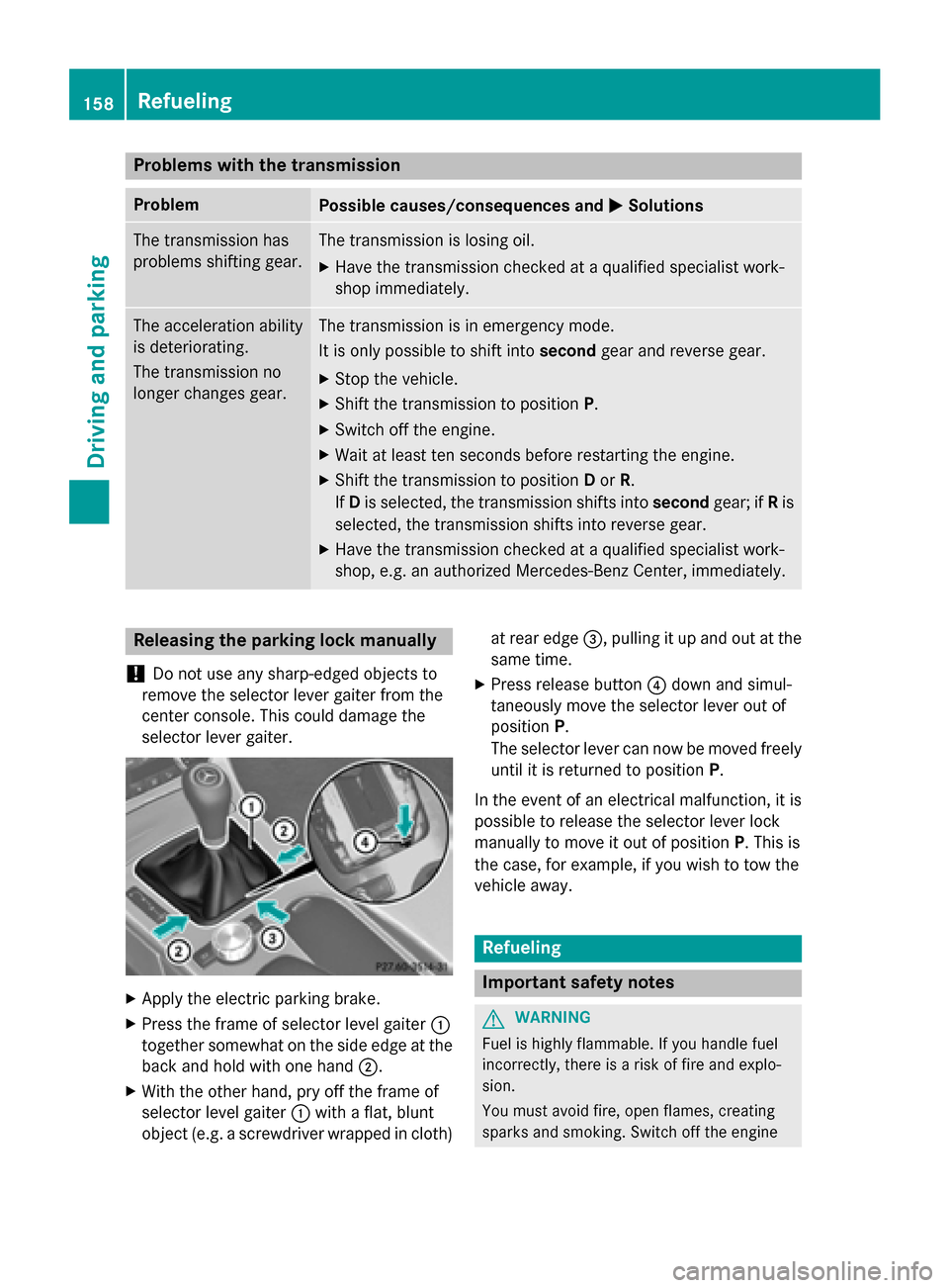
selector lever gaiter. X
Apply the electric parking brake.
X Press the frame of selector level gaiter 0043
together somewhat on the side edge at the back and hold with one hand 0044.
X With the other hand, pry off the frame of
selector level gaiter 0043with a flat, blunt
object (e.g. a screwdriver wrapped in cloth) at rear edge
0087, pulling it up and out at the
same time.
X Press release button 0085down and simul-
taneously move the selector lever out of
position P.
The selector lever can now be moved freely
until it is returned to position P.
In the event of an electrical malfunction, it is
possible to release the selector lever lock
manually to move it out of position P. This is
the case, for example, if you wish to tow the
vehicle away. Refueling
Important safety notes
G
WARNING
Fuel is highly flammable. If you handle fuel
incorrectly, there is a risk of fire and explo-
sion.
You must avoid fire, open flames, creating
sparks and smoking. Switch off the engine 158
RefuelingDriving and parking
Page 232 of 358
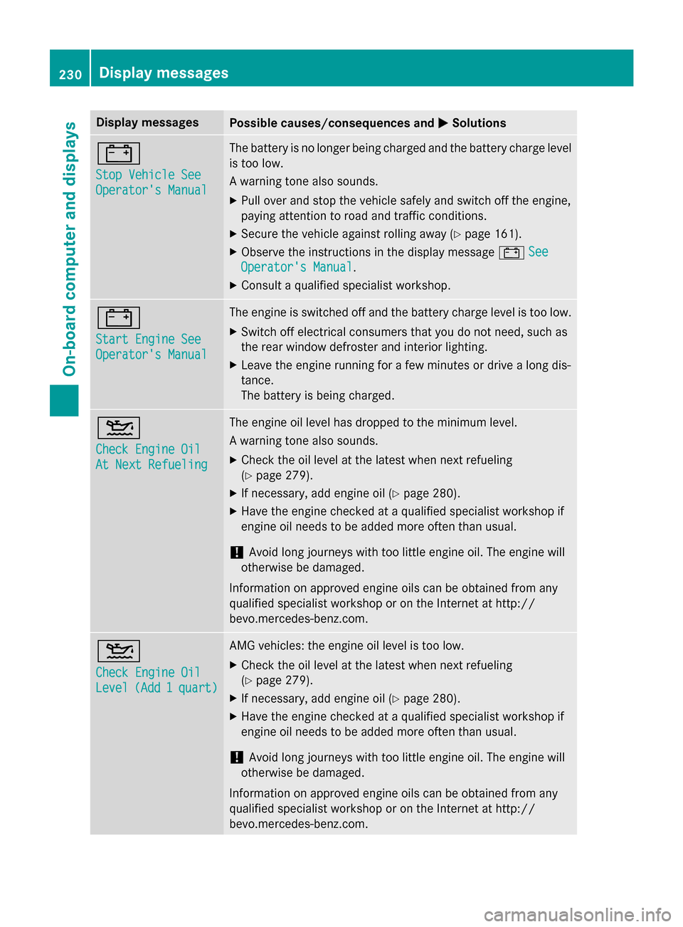
Display messages
Possible causes/consequences and
0050
0050Solutions 003D
Stop Vehicle See Stop Vehicle See
Operator's Manual Operator's Manual The battery is no longer being charged and the battery charge level
is too low.
A warning tone also sounds.
X Pull over and stop the vehicle safely and switch off the engine,
paying attention to road and traffic conditions.
X Secure the vehicle against rolling away (Y page 161).
X Observe the instructions in the display message 003DSee See
Operator's Manual
Operator's Manual .
X Consult a qualified specialist workshop. 003D
Start Engine See Start Engine See
Operator's Manual Operator's Manual The engine is switched off and the battery charge level is too low.
X Switch off electrical consumers that you do not need, such as
the rear window defroster and interior lighting.
X Leave the engine running for a few minutes or drive a long dis-
tance.
The battery is being charged. 00B2
Check Engine Oil Check Engine Oil
At Next Refueling At Next Refueling The engine oil level has dropped to the minimum level.
A warning tone also sounds.
X Check the oil level at the latest when next refueling
(Y page 279).
X If necessary, add engine oil (Y page 280).
X Have the engine checked at a qualified specialist workshop if
engine oil needs to be added more often than usual.
! Avoid long journeys with too little engine oil. The engine will
otherwise be damaged.
Information on approved engine oils can be obtained from any
qualified specialist workshop or on the Internet at http://
bevo.mercedes-benz.co m.00B2
Check Engine Oil Check Engine Oil
Level Level
(Add
(Add1
1quart)
quart) AMG vehicles: the engine oil level is too low.
X Check the oil level at the latest when next refueling
(Y page 279).
X If necessary, add engine oil (Y page 280).
X Have the engine checked at a qualified specialist workshop if
engine oil needs to be added more often than usual.
! Avoid long journeys with too little engine oil. The engine will
otherwise be damaged.
Information on approved engine oils can be obtained from any
qualified specialist workshop or on the Internet at http://
bevo.mercedes-benz.com. 230
Display messagesOn-board computer and displays
Page 281 of 358
X
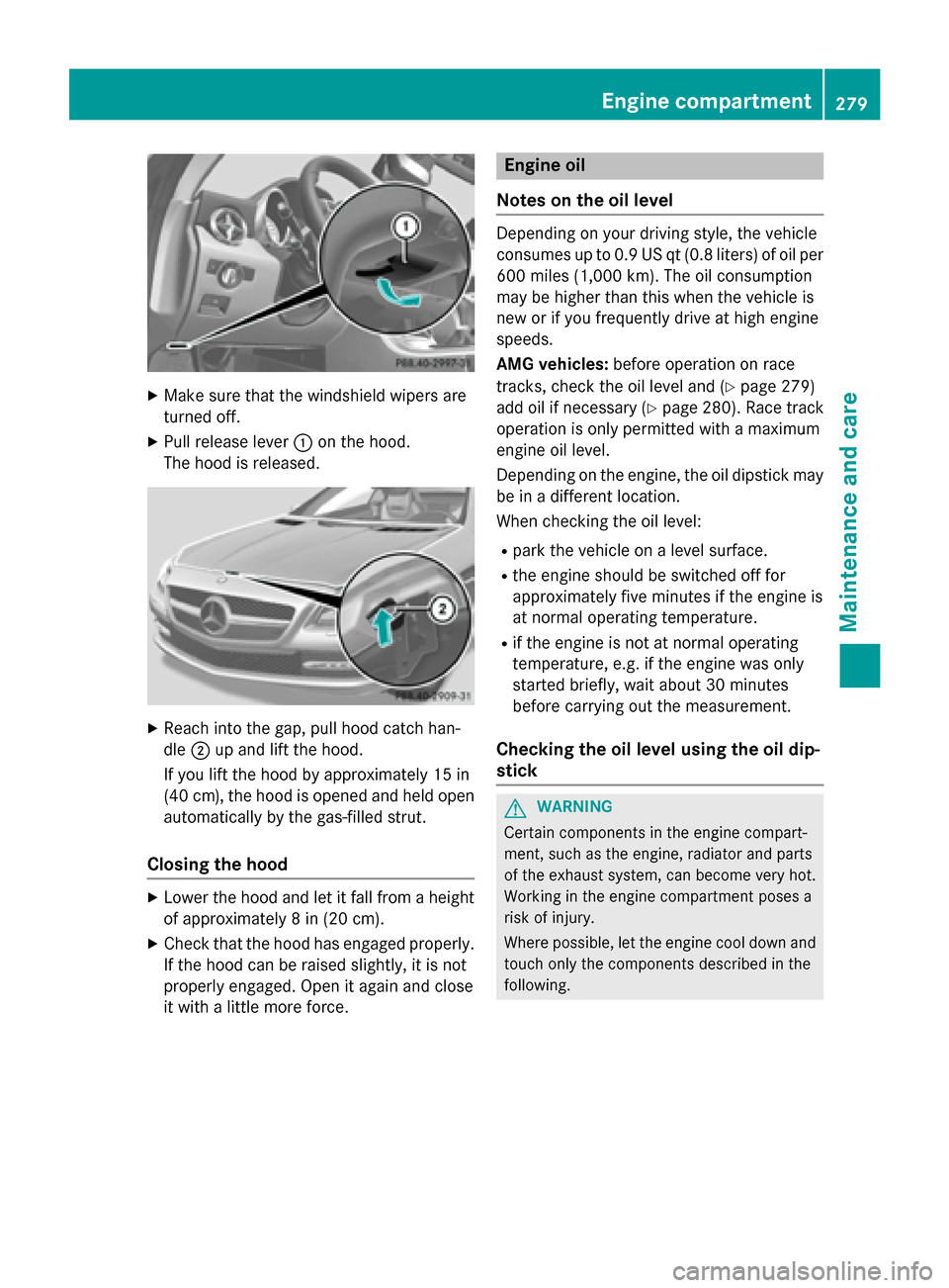
Make sure that the windshield wipers are
turned off.
X Pull release lever 0043on the hood.
The hood is released. X
Reach into the gap, pull hood catch han-
dle 0044up and lift the hood.
If you lift the hood by approximately 15 in
(40 cm), the hood is opened and held open automatically by the gas-filled strut.
Closing the hood X
Lower the hood and let it fall from a height
of approximately 8 in (20 cm).
X Check that the hood has engaged properly.
If the hood can be raised slightly, it is not
properly engaged. Open it again and close
it with a little more force. Engine oil
Notes on the oil level Depending on your driving style, the vehicle
consumes up to 0.9 US qt (0.8 liters) of oil per
600 miles (1,000 km). The oil consumption
may be higher than this when the vehicle is
new or if you frequently drive at high engine
speeds.
AMG vehicles: before operation on race
tracks, check the oil level and (Y page 279)
add oil if necessary (Y page 280). Race track
operation is only permitted with a maximum
engine oil level.
Depending on the engine, the oil dipstick may be in a different location.
When checking the oil level:
R park the vehicle on a level surface.
R the engine should be switched off for
approximately five minutes if the engine is
at normal operating temperature.
R if the engine is not at normal operating
temperature, e.g. if the engine was only
started briefly, wait about 30 minutes
before carrying out the measurement.
Checking the oil level using the oil dip-
stick G
WARNING
Certain components in the engine compart-
ment, such as the engine, radiator and parts
of the exhaust system, can become very hot.
Working in the engine compartment poses a
risk of injury.
Where possible, let the engine cool down and touch only the components described in the
following. Engine compartment
279Maintenance and care Z
Page 283 of 358
X
Replace cap 0043on the filler neck and turn
clockwise.
Ensure that the cap locks into place
securely.
X Check the oil level again with the oil dip-
stick (Y page 279).
Further information on engine oil
(Y page 349). Checking and adding other service
products
Checking coolant level G
WARNING
Certain components in the engine compart-
ment, such as the engine, radiator and parts
of the exhaust system, can become very hot.
Working in the engine compartment poses a
risk of injury.
Where possible, let the engine cool down and touch only the components described in the
following. G
WARNING
The engine cooling system is pressurized, par- ticularly when the engine is warm. When
opening the cap, you could be scalded by hotcoolant spraying out. There is a risk of injury.
Let the engine cool down before opening the
cap. Wear eye and hand protection when
opening the cap. Open the cap slowly half a
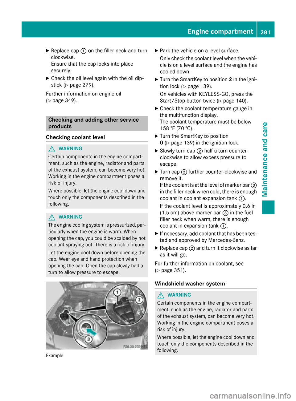
turn to allow pressure to escape. Example X
Park the vehicle on a level surface.
Only check the coolant level when the vehi- cle is on a level surface and the engine has
cooled down.
X Turn the SmartKey to position 2in the igni-
tion lock (Y page 139).
On vehicles with KEYLESS-GO, press the
Start/Stop button twice (Y page 140).
X Check the coolant temperature gauge in
the multifunction display.
The coolant temperature must be below
158 ‡ (70 †).
X Turn the SmartKey to position
0(Y page 139) in the ignition lock.
X Slowly turn cap 0044half a turn counter-
clockwise to allow excess pressure to
escape.
X Turn cap 0044further counter-clockwise and
remove it.
If the coolant is at the level of marker bar 0087
in the filler neck when cold, there is enough coolant in coolant expansion tank 0043.
If the coolant level is approximately 0.6 in
(1.5 cm) above marker bar 0087in the fuel
filler neck when warm, there is enough
coolant in expansion tank 0043.
X If necessary, add coolant that has been tes-
ted and approved by Mercedes-Benz.
X Replace cap 0044and turn it clockwise as far
as it will go.
For further information on coolant, see
(Y page 351).
Windshield washer system G
WARNING
Certain components in the engine compart-
ment, such as the engine, radiator and parts
of the exhaust system, can become very hot.
Working in the engine compartment poses a
risk of injury.
Where possible, let the engine cool down and touch only the components described in the
following. Engine compartment
281Maintenance and care Z
Page 285 of 358
Displaying service messages
X Switch on the ignition.
X Press the 0059or0065 button on the steer-
ing wheel to select the Serv. Serv.menu.
X Press the 0063or0064 button to select the
ASSYST PLUS
ASSYST PLUS submenu and confirm by
pressing the 0076button.
The service due date appears in the multi-
function display. Information about Service
Resetting the ASSYST PLUS service
interval display !
If the ASSYST PLUS service interval dis-
play has been inadvertently reset, this set-
ting can be corrected at a qualified special-
ist workshop.
Have service work carried out as described in the Maintenance Booklet. This may oth-
erwise lead to increased wear and damage
to the major assemblies or the vehicle.
A qualified specialist workshop, e.g. an
authorized Mercedes-Benz Center, will reset
the ASSYST PLUS service interval display
after the service work has been carried out.
You can also obtain further information on
maintenance work, for example.
Special service requirements The specified maintenance interval takes only
the normal operation of the vehicle into
account. Under arduous operating conditions
or increased load on the vehicle, mainte-
nance work must be carried out more fre-
quently, for example:
R regular city driving with frequent intermedi-
ate stops
R if the vehicle is primarily used to travel
short distances R
use in mountainous terrain or on poor road
surfaces
R if the engine is often left idling for long peri-
ods
Under these or similar conditions, have, for
example, the air filter, engine oil and oil filter
replaced or changed more frequently. Under
arduous operating conditions, the tires must
be checked more often. Further information
can be obtained at a qualified specialist work- shop, e.g. an authorized Mercedes-Benz Cen-
ter.
Driving abroad An extensive Mercedes-Benz Service network
is also available in other countries. You can
obtain further information from any author-
ized Mercedes-Benz Center. Care
Notes on care
H
Environmental note
Dispose of empty packaging and cleaning
cloths in an environmentally responsible man- ner.
! For cleaning your vehicle, do not use any
of the following:
R dry, rough or hard cloths
R abrasive cleaning agents
R solvents
R cleaning agents containing solvents
Do not scrub.
Do not touch the surfaces or protective
films with hard objects, e.g. a ring or ice
scraper. You could otherwise scratch or
damage the surfaces and protective film.
! Do not park the vehicle for an extended
period straight after cleaning it, particularly after having cleaned the wheels with wheel
cleaner. Wheel cleaners could cause
increased corrosion of the brake discs and brake pads/linings. For this reason, you Care
283Maintenance and care Z
Page 334 of 358
Traction
Traction is the result of friction between the
tires and the road surface.
Treadwear indicators
Narrow bars (tread wear bars) that are dis-
tributed over the tire tread. If the tire tread is level with the bars, the wear limit of 00CDin
(1.6 mm) has been reached.
Occupant distribution
The distribution of occupants in a vehicle at
their designated seating positions.
Total load limit
Rated cargo and luggage load plus
68 kilograms (150 lb) multiplied by the num-
ber of seats in the vehicle. Changing a wheel
Flat tire
The "Breakdown assistance" section
(Y page 292) contains information and notes
on how to deal with a flat tire. Information on driving with MOExtended tires in the event of
a flat tire can be found under "MOExtended
tires (tires with run-flat characteristics"
(Y page 293). Rotating the wheels
G
WARNING
Interchanging the front and rear wheels may
severely impair the driving characteristics if
the wheels or tires have different dimensions. The wheel brakes or suspension components
may also be damaged. There is a risk of acci-
dent.
Rotate front and rear wheels only if the wheels and tires are of the same dimensions.
! On vehicles equipped with a tire pressure
monitor, electronic components are loca-
ted in the wheel. Tire-mounting tools should not be used
near the valve. This could damage the elec-
tronic components.
Only have tires changed at a qualified spe-cialist workshop.
Always pay attention to the instructions and
safety notes when changing a wheel
(Y page 333).
The wear patterns on the front and rear tires
differ, depending on the operating conditions.
Rotate the wheels before a clear wear pattern has formed on the tires. Front tires typically
wear more on the shoulders and the rear tires in the center.
If your vehicle's tire configuration allows, you can rotate the wheels according to the inter-
vals in the tire manufacturer's warranty book
in your vehicle documents. If no warranty
book is available, the tires should be rotated
every 3,000 to 6,000 miles (5,000 to
10,000 km), or earlier if tire wear requires. Do not change the direction of wheel rotation.
Clean the contact surfaces of the wheel and
the brake disc thoroughly every time a wheel
is rotated. Check the tire pressure and, if nec- essary, restart the tire pressure loss warning
system or the tire pressure monitor. Direction of rotation
Tires with a specified direction of rotation
have additional benefits, e.g. if there is a risk of hydroplaning. You will only gain these ben-
efits if the correct direction of rotation is
maintained.
An arrow on the sidewall of the tire indicates
its correct direction of rotation. Storing wheels
Store wheels that are not being used in a cool, dry and preferably dark place. Protect the
tires from oil, grease, gasoline and diesel. 332
Changing a wheelWheels and tires
Page 338 of 358
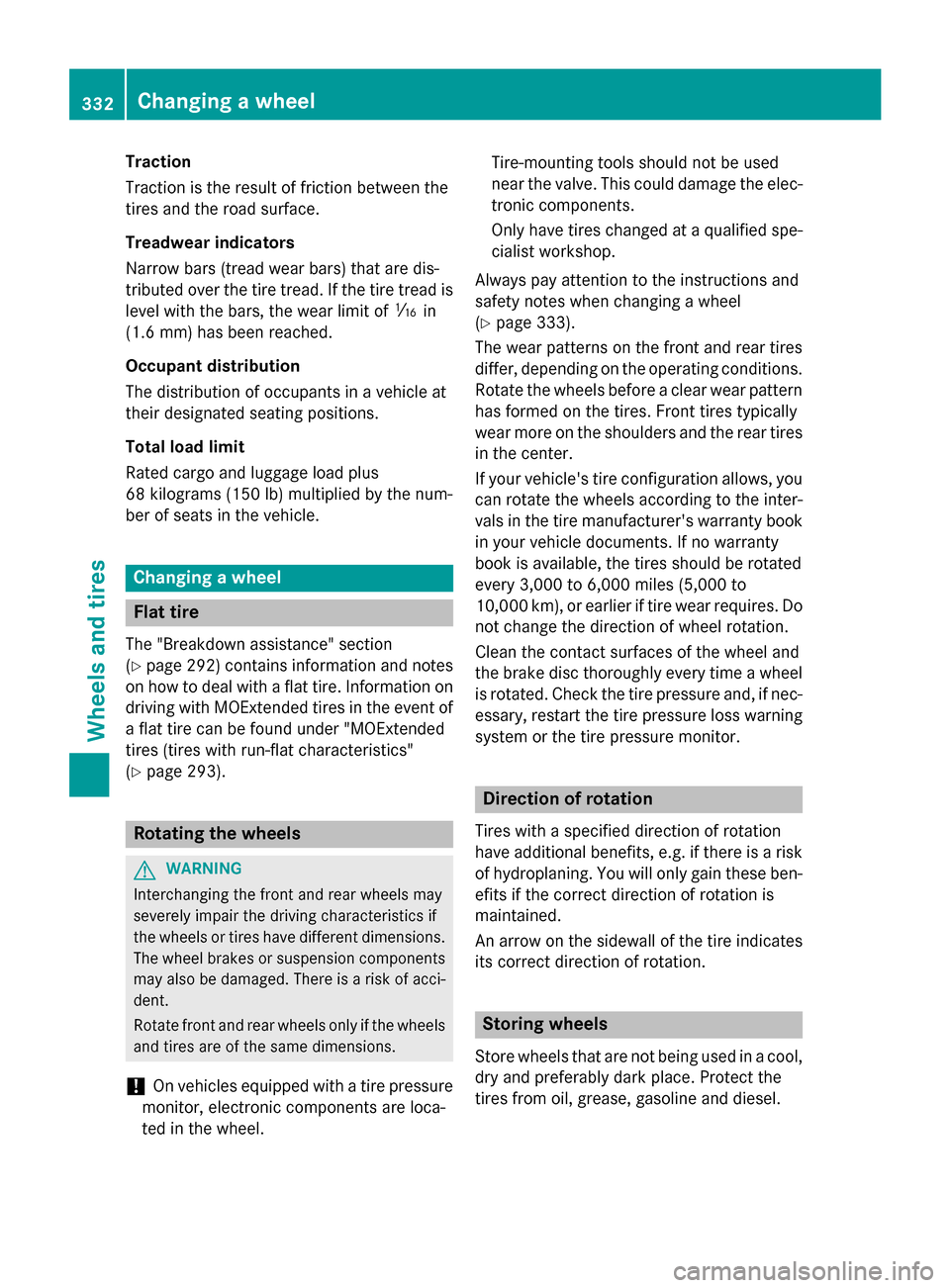
X
Unscrew the uppermost wheel bolt com-
pletely.
X Screw alignment bolt 0043into the thread
instead of the wheel bolt.
X Unscrew the remaining wheel bolts fully.
X Remove the wheel.
Mounting a new wheel G
WARNING
Oiled or greased wheel bolts or damaged
wheel bolts/hub threads can cause the wheel bolts to come loose. As a result, you could
lose a wheel while driving. There is a risk of
accident.
Never oil or grease wheel bolts. In the event ofdamage to the threads, contact a qualified
specialist workshop immediately. Have the
damaged wheel bolts or hub threads
replaced/renewed. Do not continue driving. G
WARNING
If you tighten the wheel bolts or wheel nuts
when the vehicle is raised, the jack could tip
over. There is a risk of injury.
Only tighten the wheel bolts or wheel nuts
when the vehicle is on the ground.
Always pay attention to the instructions and
safety notes in the "Changing a wheel" sec-
tion (Y page 332).
Only use wheel bolts that have been designed for the wheel and the vehicle. For safety rea-
sons, Mercedes-Benz recommends that you
only use wheel bolts which have been approved for Mercedes-Benz vehicles and the
respective wheel.
! To prevent damage to the paintwork, hold
the wheel securely against the wheel hub
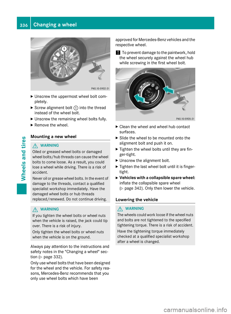
while screwing in the first wheel bolt. X
Clean the wheel and wheel hub contact
surfaces.
X Slide the wheel to be mounted onto the
alignment bolt and push it on.
X Tighten the wheel bolts until they are fin-
ger-tight.
X Unscrew the alignment bolt.
X Tighten the last wheel bolt until it is finger-
tight.
X Vehicles with a collapsible spare wheel:
inflate the collapsible spare wheel
(Y page 342). Only then lower the vehicle.
Lowering the vehicle G
WARNING
The wheels could work loose if the wheel nuts and bolts are not tightened to the specified
tightening torque. There is a risk of accident.
Have the tightening torque immediately
checked at a qualified specialist workshop
after a wheel is changed. 336
Changing a wheelWheels and tires