run flat MERCEDES-BENZ SLK-Class 2015 R172 Owner's Manual
[x] Cancel search | Manufacturer: MERCEDES-BENZ, Model Year: 2015, Model line: SLK-Class, Model: MERCEDES-BENZ SLK-Class 2015 R172Pages: 358, PDF Size: 6.18 MB
Page 7 of 358
AUTO lights
Display message ............................ 228
see Lights
Automatic engine start (ECO start/
stop function) .................................... 146
Automatic engine switch-off (ECO
start/stop function) .......................... 144
Automatic headlamp mode .............. 109
Automatic transmission Accelerator pedal position ............ .152
Automatic drive program .............. .154
Changing gear ............................... 152
Display message ............................ 238
Driving tips ................................... .152
Emergency running mode .............. 158
Kickdown ....................................... 153
Manual drive program .................... 154
Manual drive program (vehicles
with Sports package AMG) ............ 155
Overview ........................................ 151
Problem (malfunction) ................... 158
Program selector button ................ 153
Pulling away ................................... 142
Releasing the parking lock man-
ually ............................................... 158
Selector lever ................................ 151
Starting the engine ........................ 142
Steering wheel paddle shifters ...... 154
Transmission position displa y........ 151
Transmission positions .................. 152
Automatic transmission emer-
gency mode ....................................... 158 B
Backup lamp Changing bulb s.............................. 117
BAS (Brake Assist System) ................. 62
BAS PLUS (Brake Assist System
PLUS) .................................................... 62
Battery (SmartKey) Checking .......................................... 75
Important safety notes .................... 74
Replacing ......................................... 75
Battery (vehicle)
Charging ........................................ 299
Display message ............................ 229
Important safety notes .................. 297 Jump starting ................................. 301
Overview ........................................ 297
Belt
see Seat belts
Blind Spot Assist
Activating/deactivating ................. 204
Display message ............................ 232
Notes/function .............................. 189
Brake Assist
see BAS (Brake Assist System)
Brake fluid
Display message ............................ 220
Notes ............................................. 350
Brake force distribution, elec-
tronic
see EBD (electronic brake force
distribution)
Brake lamps
Display message ............................ 226
Brakes
ABS .................................................. 61
BAS .................................................. 62
BAS PLUS ........................................ 62
Brake fluid (notes) ......................... 350
Display message ............................ 213
EBD .................................................. 67
High-performance brake system .... 168
Important safety notes .................. 166
Maintenance .................................. 167
Parking brake ................................ 162
Riding tips ...................................... 166
Warning lamp ................................. 245
Breakdown
see Flat tire
see Towing away
Brightness control (instrument
cluster lighting) ................................... 31
Bulbs see Replacing bulbs C
California Important notice for retail cus-
tomers and lessees .......................... 23
Calling up a malfunction
see Display messages Index
5
Page 11 of 358
ECO start/stop function
Automatic engine start .................. 146
Automatic engine switch-off .......... 144
Deactivating/activating ................ .147
General information ....................... 144
Important safety notes .................. 143
Introduction ................................... 143
Electronic Stability Program
see ESP ®
(Electronic Stability Program)
Emergency
Automatic measures after an acci-
dent ................................................. 57
Emergency release
Driver's door ................................... .80
Trunk ............................................... 83
Vehicle ............................................. 80
Emergency spare wheel
General notes ................................ 341
Important safety notes .................. 341
Removing ....................................... 341
Stowing .......................................... 342
Technical data ...............................3 44
Emergency Tensioning Devices
Activation ......................................... 54
Emissions control
Service and warranty information .... 22
Engine
Check Engine warning lamp ........... 251
Display message ............................ 228
ECO start/stop function ................ 143
Engine number ............................... 347
Irregular running ............................ 149
Jump-starting ................................. 301
Starting problems .......................... 149
Starting the engine with the
SmartKey ....................................... 142
Starting with KEYLESS-GO ............. 142
Switching off .................................. 162
Tow-starting (vehicle) ..................... 306
Engine electronics
Problem (malfunction) ................... 149
Engine oil
Adding .......................................... .280
Additives ........................................ 350
Checking the oil level ..................... 279
Checking the oil level using the
dipstick .......................................... 279 Display message ............................ 230
Filling capacity ............................... 350
Notes about oil grades ................... 349
Notes on oil level/consumption .... 279
Temperature (on-board com-
puter) ............................................. 208
Viscosity ........................................ 350
ESP ®
(Electronic Stability Pro-
gram) AMG menu (on-board computer) ... 209
Characteristics ................................. 64
Deactivating/activating (AMG
vehicles) .......................................... 65
Deactivating/activating (notes;
except AMG vehicles) ..................... .64
Display message ............................ 213
ETS .................................................. 63
Function/note s................................ 63
General notes .................................. 63
Important safety information ........... 64
Warning lamp ................................. 247
ETS (Electronic Traction System) ....... 63
Exhaust check ................................... 165
Exhaust pipe (cleaning instruc-
tions) .................................................. 287
Exterior lighting Setting options .............................. 108
see Lights
Exterior mirrors
Adjusting ....................................... 103
Dipping (automatic) ....................... 104
Folding in/out (automatically )....... 104
Folding in/out (electrically) ........... 104
Folding in when locking (on-board
computer) ...................................... 208
Out of position (troubleshooting) ... 104
Storing settings (memory func-
tion) ............................................... 106
Storing the parking position .......... 105
Eyeglasses compartment ................. 257 F
Filler cap see Fuel filler flap
Filling capacities (Technical data) ... 347
Flat tire MOExtended tire s.......................... 293 Index
9
Page 20 of 358
Increased vehicle weight due to
optional equipment (definition) ...... 330
Kilopascal (kPa) (definition) ........... 330
Labeling (overview) ........................ 326
Load bearing index (definition) ...... 331
Load index .....................................3 28
Load index (definition) ................... 331
M+S tires ....................................... 312
Maximum loaded vehicle weight
(definition) ..................................... 330
Maximum load on a tire (defini-
tion) ............................................... 331
Maximum permissible tire pres-
sure (definition) ............................ .331
Maximum tire load ......................... 328
Maximum tire load (definition) ....... 331
MOExtended tires .......................... 312
Optional equipment weight (defi-
nition) ............................................ 331
Overview ........................................ 310
PSI (pounds per square inch) (def-
inition) .......................................... .331
Replacing ....................................... 332
Service life ..................................... 312
Sidewall (definition) ....................... 331
Speed rating (definition) ................ 330
Storing .......................................... .332
Structure and characteristics
(definition) ..................................... 329
Summer tires ................................. 312
Temperature .................................. 325
TIN (Tire Identification Number)
(definition) ..................................... 331
Tire bead (definition) ..................... .331
Tire pressure (definition) ................ 331
Tire pressures (recommended) ...... 330
Tire size (data) ............................... 337
Tire size designation, load-bearing capacity, speed rating .................... 326
Tire tread ....................................... 311
Tire tread (definition) ..................... 331
Total load limit (definition) ............. 332
Traction ......................................... 325
Traction (definition) ....................... 332
Tread wea r..................................... 325
Uniform Tire Quality Grading
Standards ...................................... 324 Uniform Tire Quality Grading
Standards (definition) .................... 330
Wear indicator (definition) ............. 332
Wheel and tire combination ........... 339
Wheel rim (definition) .................... 330
see Flat tire
Towing
Important safety guidelines ........... 303
Installing the towing eye ................ 304
Removing the towing eye ............... 304
With the rear axle raised ................ 305
Towing away
With both axles on the ground ....... 305
Tow-starting
Emergency engine starting ............ 306
Important safety notes .................. 303
Installing the towing eye ................ 304
Removing the towing eye ............... 304
Transmission
Selector lever ................................ 151
see Automatic transmission
see Manual transmission
Transporting the vehicle .................. 305
Trim pieces (cleaning instruc-
tions) .................................................. 288
Trip computer (on-board com-
puter) .................................................. 197
Trip odometer Calling up ....................................... 197
Resetting (on-board computer) ...... 198
Trunk
Emergency release .......................... 82
Important safety notes .................... 80
Locking separately ........................... 82
Opening/closing (manually from
outside) ............................................ 81
Opening (automatically from out-
side) ................................................. 82
Overview .......................................... 80
Trunk lid
Display message ............................ 240
Opening/closing .............................. 80
Opening dimensions ...................... 353
Trunk load (maximum) ...................... 35318
Index
Page 157 of 358
Upshifting
X Briefly press the selector lever to the right
towards D+.
or X Pull the right-hand steering wheel paddle
shifter (Y page 154).
In cases where it is permissible, the auto-
matic transmission shifts up to the next
gear.
i If the maximum engine speed on the cur-
rently engaged gear is reached and you
continue to accelerate, the automatic
transmission automatically shifts up in
order to prevent engine damage.
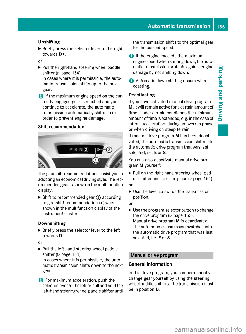
Shift recommendation The gearshift recommendations assist you in
adopting an economical driving style. The rec- ommended gear is shown in the multifunction
display.
X Shift to recommended gear 0044according
to gearshift recommendation 0043when
shown in the multifunction display of the
instrument cluster.
Downshifting X Briefly press the selector lever to the left
towards D–.
or
X Pull the left-hand steering wheel paddle
shifter (Y page 154).
In cases where it is permissible, the auto-
matic transmission shifts down to the next
gear.
i For maximum acceleration, push the
selector lever to the left or pull and hold the
left-hand steering wheel paddle shifter until the transmission shifts to the optimal gear
for the current speed.
i If the engine exceeds the maximum
engine speed when shifting down, the auto-
matic transmission protects against engine damage by not shifting down.
i Automatic down shifting occurs when
coasting.
Deactivating
If you have activated manual drive program
M, it will remain active for a certain amount of time. Under certain conditions the minimum
amount of time is extended, e.g. in the case oflateral acceleration, during an overrun phase
or when driving on steep terrain.
If manual drive program Mhas been deacti-
vated, the automatic transmission shifts into
the automatic drive program that was last
selected, i.e. Eor S.
You can also deactivate manual drive pro-
gram Myourself:
X Pull on the right-hand steering wheel pad-
dle shifter and hold it in place (Y page 154).
or
X Use the lever to switch the transmission
position.
or
X Use the program selector button to change
the drive program (Y page 153).
Manual drive program Mis deactivated.
The automatic transmission switches into
the automatic drive program that was last
selected, i.e. Eor S. Manual drive program
General information In this drive program, you can permanently
change gear yourself by using the steering
wheel paddle shifters. The transmission must
be in position D. Automatic transmission
155Driving and parking Z
Page 167 of 358
a distance of 44 ft (approximately 14 m) per
second.
Drive sensibly – save fuel Observe the following tips to save fuel:
R The tires should always be inflated to the
recommended tire pressure.
R Remove unnecessary loads.
R Warm up the engine at low engine speeds.
R Avoid frequent acceleration or braking.
R Observe the service intervals in the Main-
tenance Booklet or in the service interval
display. Have all the maintenance work car- ried in accordance with Daimler AG regu-
lations.
Fuel consumption also increases when driv-
ing in cold weather, in stop-start traffic and in
hilly terrain.
Drinking and driving G
WARNING
Drinking and driving and/or taking drugs and driving are very dangerous combinations.
Even a small amount of alcohol or drugs can
affect your reflexes, perceptions and judg-
ment.
The possibility of a serious or even fatal acci-
dent is greatly increased when you drink or
take drugs and drive.
Do not drink or take drugs and drive or allow
anyone to drive who has been drinking or tak-
ing drugs.
Emission control G
WARNING
Combustion engines emit poisonous exhaust
gases such as carbon monoxide. Inhaling
these exhaust gases leads to poisoning. There is a risk of fatal injury. Therefore never leave
the engine running in enclosed spaces with-
out sufficient ventilation. Certain engine systems are designed to keep
the level of poisonous components in exhaust fumes within legal limits.
These systems only work at peak efficiency if they are serviced exactly in accordance with
the manufacturer's specifications. All work
on the engine must be carried out only by
qualified and authorized Mercedes-Benz
technicians.
The engine settings must not be changed
under any circumstances. Furthermore, all
specific service work must be carried out at
regular intervals and in accordance with the
Mercedes-Benz service requirements. Details
can be found in the Maintenance Booklet. ECO display
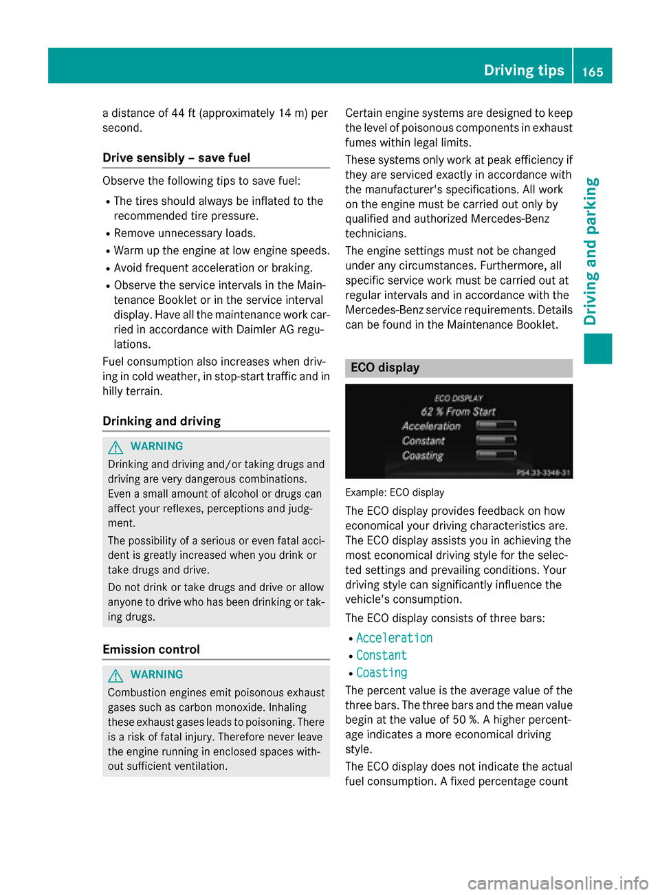
Example: ECO display
The ECO display provides feedback on how
economical your driving characteristics are.
The ECO display assists you in achieving the
most economical driving style for the selec-
ted settings and prevailing conditions. Your
driving style can significantly influence the
vehicle's consumption.
The ECO display consists of three bars:
R Acceleration Acceleration
R Constant
Constant
R Coasting
Coasting
The percent value is the average value of the three bars. The three bars and the mean value
begin at the value of 50 %. A higher percent-
age indicates a more economical driving
style.
The ECO display does not indicate the actual fuel consumption. A fixed percentage count Driving tips
165Driving and parking Z
Page 238 of 358
Tires
Display messages
Possible causes/consequences and
0050
0050Solutions Check
Check
Tire Pressure Soon Tire Pressure Soon Canada only:
The tire pressure loss warning system has detected a significant
loss in pressure.
A warning tone also sounds.
G WARNING
With tire pressures which are too low, there is a risk of the fol-
lowing hazards:
R they may burst, especially as the load and vehicle speed
increase.
R they may wear excessively and/or unevenly, which may greatly
impair tire traction.
R the driving characteristics, as well as steering and braking, may
be greatly impaired.
There is a risk of an accident.
X Stop the vehicle without making any sudden steering or braking
maneuvers. Pay attention to the traffic conditions as you do so.
X Secure the vehicle against rolling away (Y page 161).
X Check the tires and, if necessary, follow the instructions for a
flat tire (Y page 292).
X Check the tire pressures and, if necessary, correct the tire pres-
sure.
X Restart the tire pressure loss warning system when the tire
pressure is correct (Y page 318).Check Check
Tire
TirePressure
Pressure
Then Restart Run
Then Restart Run
Flat Indicator Flat Indicator Canada only:
The tire pressure loss warning system generated a display mes-
sage and has not been restarted since.
X Set the correct tire pressure in all four tires.
X Restart the tire pressure loss warning system (Y page 318).Run Flat Indicator Run Flat Indicator
Inoperative Inoperative Canada only:
The tire pressure loss warning system is faulty.
X Visit a qualified specialist workshop. Please Correct Please Correct
Tire Pressure Tire Pressure The tire pressure is too low in at least one of the tires, or the tire
pressure difference between the wheels is too great.
X Check the tire pressures at the next opportunity (Y page 318).
X If necessary, correct the tire pressure.
X Restart the tire pressure monitor (Y page 321).236
Display
messagesOn-board computer and displays
Page 260 of 358
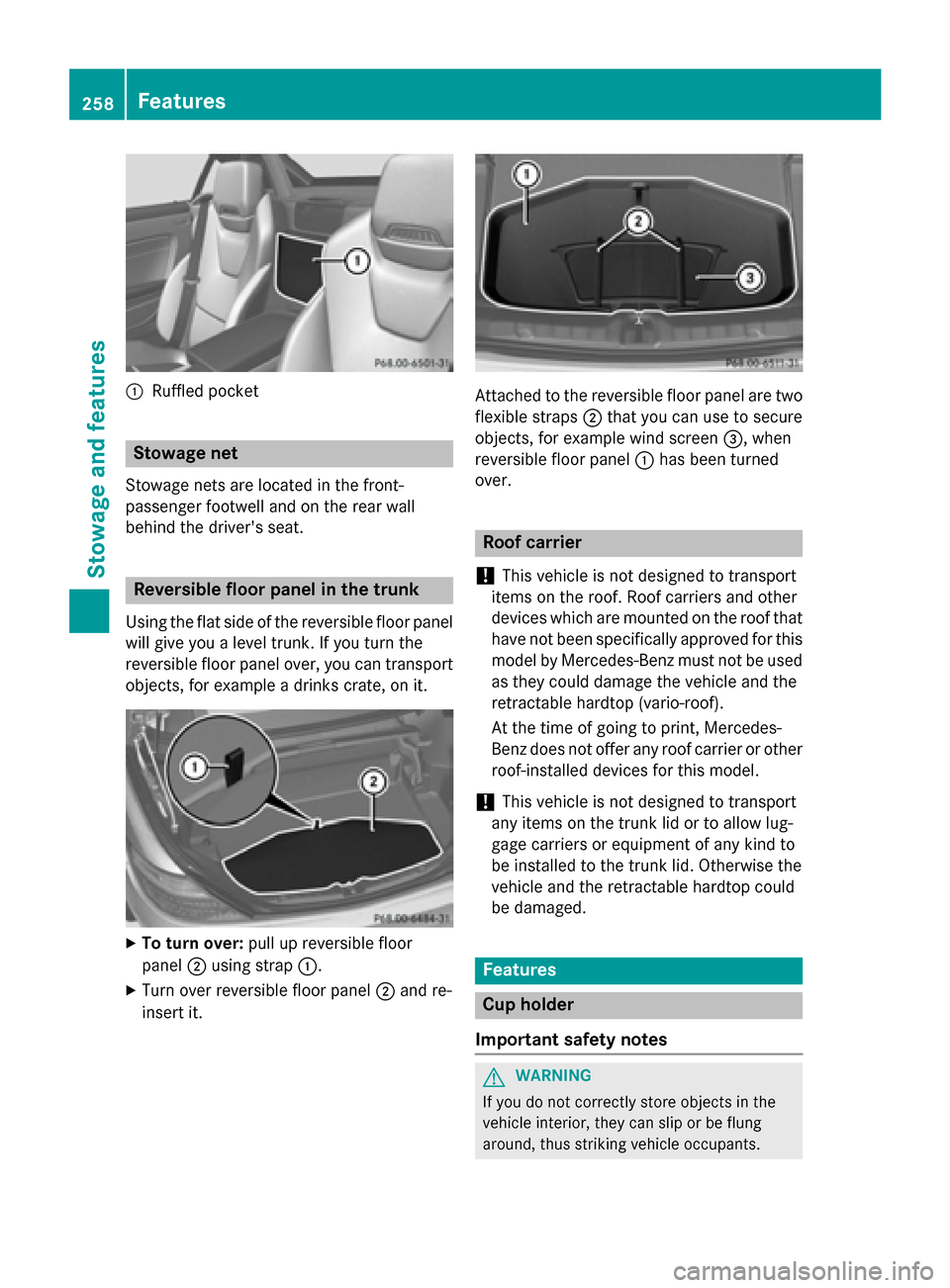
0043
Ruffled pocket Stowage net
Stowage nets are located in the front-
passenger footwell and on the rear wall
behind the driver's seat. Reversible floor panel in the trunk
Using the flat side of the reversible floor panel
will give you a level trunk. If you turn the
reversible floor panel over, you can transport objects, for example a drinks crate, on it. X
To turn over: pull up reversible floor
panel 0044using strap 0043.
X Turn over reversible floor panel 0044and re-
insert it. Attached to the reversible floor panel are two
flexible straps 0044that you can use to secure
objects, for example wind screen 0087, when
reversible floor panel 0043has been turned
over. Roof carrier
! This vehicle is not designed to transport
items on the roof. Roof carriers and other
devices which are mounted on the roof that
have not been specifically approved for this
model by Mercedes-Benz must not be used as they could damage the vehicle and the
retractable hardtop (vario-roof).
At the time of going to print, Mercedes-
Benz does not offer any roof carrier or other roof-installed devices for this model.
! This vehicle is not designed to transport
any items on the trunk lid or to allow lug-
gage carriers or equipment of any kind to
be installed to the trunk lid. Otherwise the
vehicle and the retractable hardtop could
be damaged. Features
Cup holder
Important safety notes G
WARNING
If you do not correctly store objects in the
vehicle interior, they can slip or be flung
around, thus striking vehicle occupants. 258
FeaturesStowage and fea
tures
Page 294 of 358
Useful information
i This Operator's manual describes all
models and all standard and optional equip- ment of your vehicle available at the time of
publication of the Operator's manual.
Country-specific differences are possible.
Please note that your vehicle may not be
equipped with all features described. This
also applies to safety-related systems and
functions.
i Read the information on qualified special-
ist workshops (Y page 26). Where will I find...?
Vehicle tool kit
General notes The vehicle tool kit can be found in the stow-
age well under the trunk floor.
i Apart from certain country-specific varia-
tions, the vehicles are not equipped with a
tire-change tool kit. Some tools for chang-
ing a wheel are specific to the vehicle. For
more information on which tools are
required to perform a wheel change on your
vehicle, consult a qualified specialist work-
shop.
Tools required for changing a wheel may
include, for example:
R Jack
R Wheel chock
R Lug wrench
R Ratchet wrench
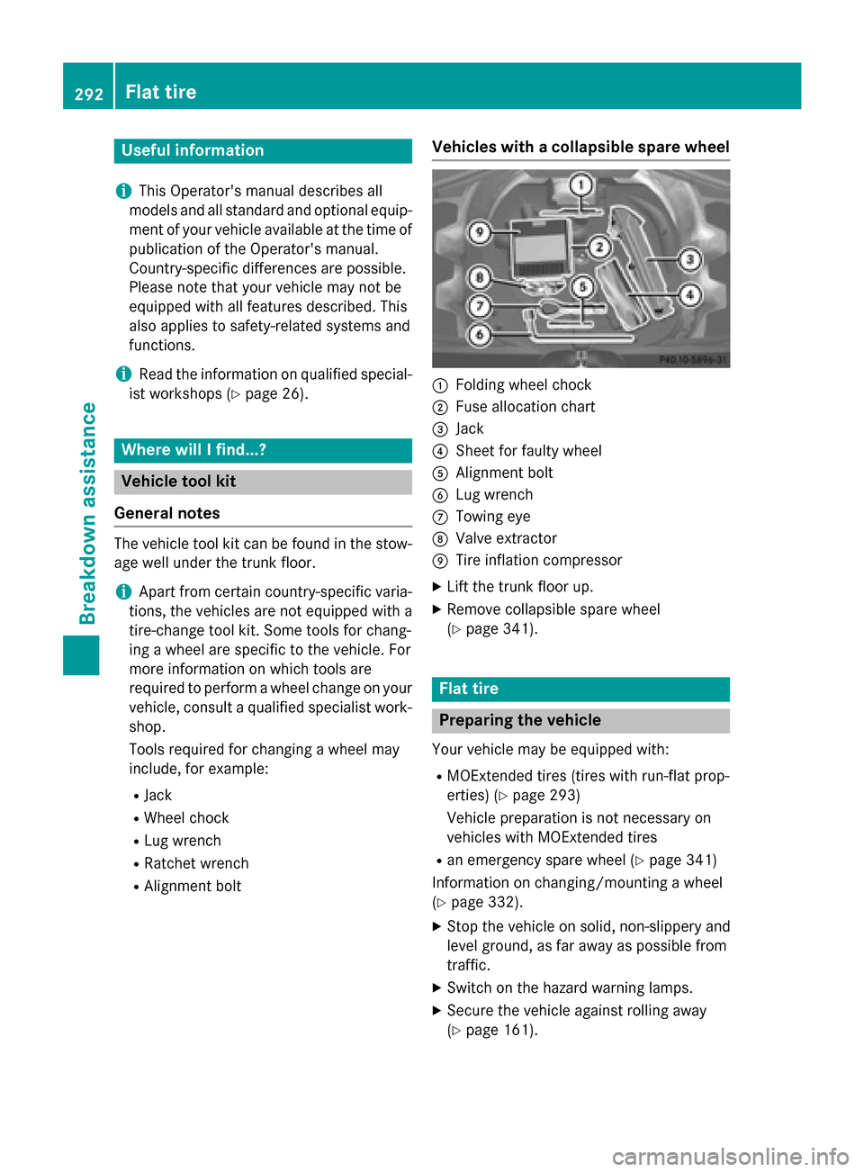
R Alignment bolt Vehicles with a collapsible spare wheel 0043
Folding wheel chock
0044 Fuse allocation chart
0087 Jack
0085 Sheet for faulty wheel
0083 Alignment bolt
0084 Lug wrench
006B Towing eye
006C Valve extractor
006D Tire inflation compressor
X Lift the trunk floor up.
X Remove collapsible spare wheel
(Y page 341). Flat tire
Preparing the vehicle
Your vehicle may be equipped with: R MOExtended tires (tires with run-flat prop-
erties) (Y page 293)
Vehicle preparation is not necessary on
vehicles with MOExtended tires
R an emergency spare wheel (Y page 341)
Information on changing/mounting a wheel
(Y page 332).
X Stop the vehicle on solid, non-slippery and
level ground, as far away as possible from
traffic.
X Switch on the hazard warning lamps.
X Secure the vehicle against rolling away
(Y page 161). 292
Flat tireBreakdown assistance
Page 295 of 358
X
If possible, bring the front wheels into the
straight-ahead position.
X Switch off the engine.
X Vehicles without KEYLESS-GO: remove
the SmartKey from the ignition lock.
X Vehicles with KEYLESS-GO: open the
driver's door.
The on-board electronics now have status
0. This is the same as the SmartKey having
been removed.
X Vehicles with KEYLESS-GO: remove the
Start/Stop button from the ignition lock
(Y page 140).
X All occupants must get out of the vehicle.
Make sure that they are not endangered as they do so.
X Make sure that no one is near the danger
area while a wheel is being changed. Any-
one who is not directly assisting in the
wheel change should, for example, stand
behind the barrier.
X Get out of the vehicle. Pay attention to traf-
fic conditions when doing so.
X Close the driver's door. MOExtended tires (tires with run-flat
properties)
General notes With MOExtended tires (tires with run flat
characteristics), you can continue to drive
your vehicle even if there is a total loss of
pressure in one or more tires. The affected
tire must not show any clearly visible damage.
You can recognize MOExtended tires by the
MOExtended marking which appears on the
sidewall of the tire. You will find this marking next to the tire size designation, the load-
bearing capacity and the speed index
(Y page 326).
MOExtended tires may only be used in con-
junction with an active tire pressure loss
warning system or with an active tire pressure
monitor. If the pressure loss warning message
appears in the multifunction display:
R Observe the instructions in the display
messages (Y page 236).
R Check the tire for damage.
R If driving on, observe the following notes.
The maximum driving distance is approx-
imately 50 miles (80 km) when the vehicle is
partially laden and approximately 18 miles
(30 km) when the vehicle is fully laden.
In addition to the vehicle load, the driving dis- tance possible depends upon:
R Speed
R Road condition
R Outside temperature
The driving distance possible in run-flat mode may be reduced by extreme driving condi-
tions/maneuvers, or it can be increased
through a moderate style of driving.
The maximum permissible distance which
can be driven in run-flat mode is counted fromthe moment the tire pressure loss warning
appears in the multifunction display.
You must not exceed a maximum speed of
50 mph (80 km/h).
i When replacing one or all tires, make sure
that you use only tires:
R of the size specified for the vehicle and
R marked "MOExtended"
If a tire has gone flat and cannot be
replaced with a MOExtended tire, a stand-
ard tire may be used as a temporary meas-
ure. Make sure that you use the proper size and type (summer or winter tire).
i Vehicles equipped with MOExtended tires
are not equipped with a TIREFIT kit at the
factory. It is therefore recommended that
you additionally equip your vehicle with a
TIREFIT kit if you mount tires that do not
feature run-flat properties, e.g. winter tires. A TIREFIT kit is available, for example, from
a qualified specialist workshop. Flat tire
293Breakdown assistance
Page 297 of 358
X
Do not remove any foreign objects which
have penetrated the tire, e.g. screws or
nails.
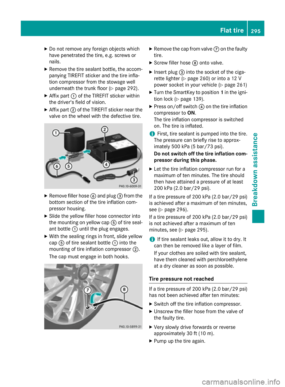
X Remove the tire sealant bottle, the accom-
panying TIREFIT sticker and the tire infla-
tion compressor from the stowage well
underneath the trunk floor (Y page 292).
X Affix part 0043of the TIREFIT sticker within
the driver's field of vision.
X Affix part 0044of the TIREFIT sticker near the
valve on the wheel with the defective tire. X
Remove filler hose 0084and plug 0087from the
bottom section of the tire inflation com-
pressor housing.
X Slide the yellow filler hose connector into
the mounting on yellow cap 0083of tire seal-
ant bottle 0043until the plug engages.
X With the sealing rings in front, slide yellow
cap 0083of tire sealant bottle 0043into the
mounting of tire inflation compressor 0044.
The cap must engage in both hooks. X
Remove the cap from valve 006Bon the faulty
tire.
X Screw filler hose 006Conto valve.
X Insert plug 0087into the socket of the ciga-
rette lighter (Y page 260) or into a 12 V
power socket in your vehicle (Y page 261)
X Turn the SmartKey to position 1in the igni-
tion lock (Y page 139).
X Press on/off switch 0085on the tire inflation
compressor to ON.
The tire inflation compressor is switched
on. The tire is inflated.
i First, tire sealant is pumped into the tire.
The pressure can briefly rise to approx-
imately 500 kPa (5 bar/73 psi).
Do not switch off the tire inflation com-
pressor during this phase.
X Let the tire inflation compressor run for a
maximum of ten minutes. The tire should
then have attained a pressure of at least
200 kPa (2.0 bar/29 psi).
If a tire pressure of 200 kPa (2.0 ba r/29 psi)
is achieved after a maximum of ten minutes,
see (Y page 296).
If a tire pressure of 200 kPa (2.0 bar/29 psi) is not achieved after a maximum of ten
minutes, see (Y page 295).
i If tire sealant leaks out, allow it to dry. It
can then be removed like a layer of film.
If your clothes are soiled with tire sealant,
have them cleaned with perchloroethylene at a dry cleaner as soon as possible.
Tire pressure not reached If a tire pressure of 200 kPa (2.0 bar/29 psi)
has not been achieved after ten minutes:
X Switch off the tire inflation compressor.
X Unscrew the filler hose from the valve of
the faulty tire.
X Very slowly drive forwards or reverse
approximately 30 ft (10 m).
X Pump up the tire again. Flat tire
295Breakdown assistance Z