clock MERCEDES-BENZ SLK ROADSTER 2008 Owners Manual
[x] Cancel search | Manufacturer: MERCEDES-BENZ, Model Year: 2008, Model line: SLK ROADSTER, Model: MERCEDES-BENZ SLK ROADSTER 2008Pages: 273, PDF Size: 4.42 MB
Page 62 of 273
Seats
59
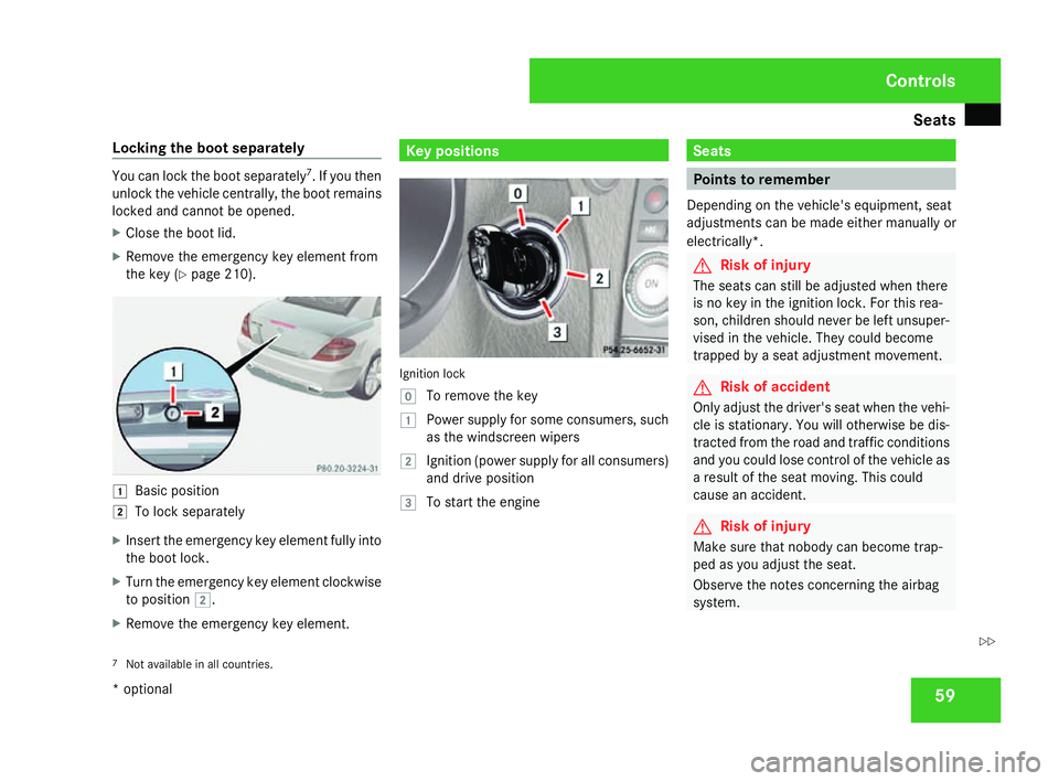
Locking the boot separately You can lock the boot separately
7
. If you then
unlock the vehicle centrally, the boot remains
locked and cannot be opened.
X Close the boot lid.
X Remove the emergency key element from
the key (Y page 210). $
Basic position
% To lock separately
X Insert the emergency key element fully into
the boot lock.
X Turn the emergency key element clockwise
to position %.
X Remove the emergency key element. Key positions
Ignition loc
k
} To remove the key
$ Power supply for some consumers, such
as the windscreen wipers
% Ignition (power supply for all consumers)
and drive positio n
& To start the engine Seats
Points to remember
Depending on the vehicle's equipment, seat
adjustments can be made either manually or
electrically*. G
Risk of injury
The seats can still be adjusted when there
is no key in the ignition lock. For this rea -
son, children should never be left unsuper-
vised in the vehicle. They could become
trapped by a seat adjustment movement. G
Risk of accident
Only adjust the driver's seat when the vehi-
cle is stationary. You will otherwise be dis-
tracted from the road and traffic conditions
and you could lose control of the vehicle as
a result of the seat moving. This could
cause an accident. G
Risk of injury
Make sure that nobody can become trap -
ped as you adjust the seat.
Observe the notes concerning the airbag
system.
7 Not available in all countries. Controls
* optional
171_AKB; 3; 4, en-GB
vpfaff7,
2007-11-13T10:50:25+01:00 - Seite 59 Z
Page 107 of 273
On-board computer
104
Setting the tim
e
X Use the jbutton to select Clock,
hours Press R to confir m(or Clock ,
minutes Press R to confirm).
X Press the æorç button to set a
value.
X Press the reset button Jon the left of the
instrument cluster.
The set time is stored.
Setting the date
X Press the jbutton to select Set date
Day (orSet date Month orSet date
Year).
X Press the æorç button to set the
values.
X Press the j,è orÿ button to
select a different display.
Setting constant headlamp mode If you have selected constant headlamp mode
and the light switch is set to the
Mor
U position, the side lamps, dipped-beam
headlamps and licence plate lighting switc h
on automatically when the engine is running. Turning the light switch to a different position
switches on the corresponding lights.
In countries in which constant headlamp
mode is a legal requirement,
Constantis the
factory setting.
X Press the èor· button to select the
Settings menu.
X Press the jbutton to call up the selec-
tion of submenus.
X Press the æorç button to select the
Lighting submenu.
X Press the jbutton to select Headlamp
mode.
X Press the æorç button to set the
switch-on mode for the headlamps to Man-
ual orConstant (constant headlamp
mode).
X Press the j,è orÿ button to
select a different display. Switching the surround lighting on or
off If the surround lighting is switched on, the
following lights will be switched on automat-
ically in the dark after you have unlocked the
vehicle using the key:
R the side lamps
R the tail lamps
R the licence plate lighting
R the front foglamps
The surround lighting switches off automati-
cally if you open the driver's door or after 40
seconds.
X Press the èor· button to select the
Settings menu.
X Press the jbutton to call up the selec-
tion of submenus.
X Press the æorç button to select the
Lighting submenu.
X Press the jbutton to select the Sur-
round lighting function. Cont
rols
171_AKB; 3; 4, en-GB
vpfaff7,
2007-11-13T10:50:25+01:00 - Seite 104
Page 129 of 273
Air conditionin
g126 Function Recommendation/Notes
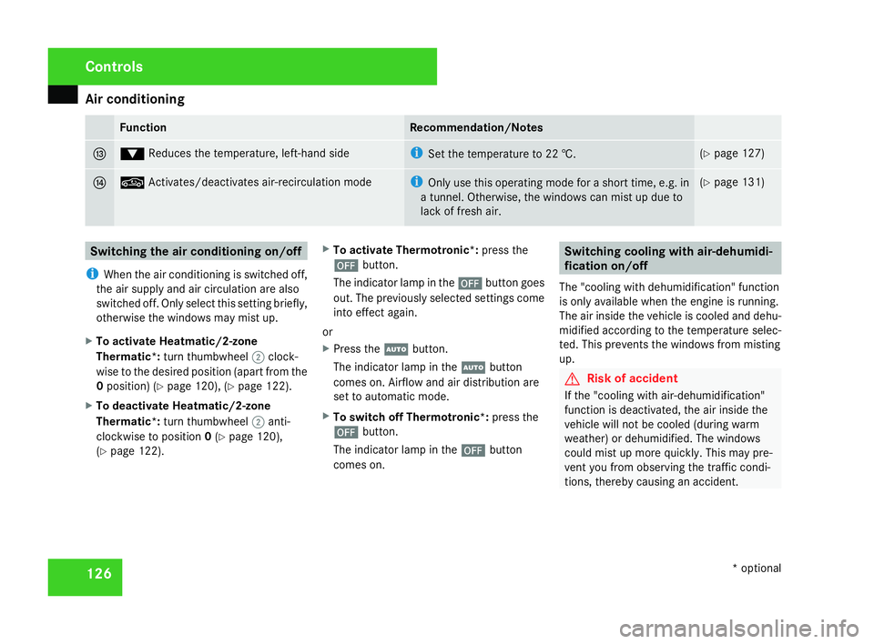
d %
Reduces the temperature, left-hand side i
Set the temperature to 22 †. (
Y page 127 ) e ,
Activates/deactivates air-recirculation mod e i
Only use this operating mode for a short time, e.g. in
a tunnel. Otherwise, the windows can mist up due to
lack of fresh air. (
Y page 131 ) Switching the air conditioning on/off
i When the air conditioning is switched off,
the air supply and air circulation are also
switched off. Only select this setting briefly,
otherwise the windows may mist up.
X To activate Heatmatic/2-zone
Thermatic *:turn thumbwheel 2clock-
wise to the desired position (apart from the
0 position) (Y page 120), (Y page 122).
X To deactivate Heatmatic/2-zone
Thermatic *:turn thumbwheel 2anti-
clockwise to position 0(Y page 120),
( Y page 122). X
To activate Thermotronic*: press the
´ button.
The indicator lamp in the ´button goes
out. The previously selected settings come
into effect again.
or
X Press the Ubutton.
The indicator lamp in the Ubutton
comes on. Airflow and air distribution are
set to automatic mode.
X To switch off Thermotronic*: press the
´ button.
The indicator lamp in the ´button
comes on. Switching cooling with air-dehumidi-
fication on/off
The "cooling with dehumidification" function
is only available when the engine is running.
The air inside the vehicle is cooled and dehu-
midified according to the temperature selec-
ted. This prevents the windows from mistin g
up. G
Risk of accident
If the "cooling with air-dehumidification"
function is deactivated, the air inside the
vehicle will not be cooled (during warm
weather) or dehumidified. The window s
could mist up more quickly. This may pre -
vent you from observing the traffic condi-
tions, thereby causing an accident. Controls
* optional
171_AKB; 3; 4, en-GB
vpfaff7,
2007-11-13T10:50:25+01:00 - Seite 126
Page 130 of 273
Air conditionin
g 127H
Environmental not
e
The cooling system uses the refrigerant
R134A. This refrigerant does not damage
the earth's ozone layer.
i Condensation may drip from the under-
side of the vehicle when Thermatic is in
cooling mode.
The "cooling with air dehumidification" func-
tion is only available with 2-zone Thermatic*
or Thermotronic* .
X To activate: press the914
/œ 15
but-
ton.
The indicator lamp in the 9/œ but-
ton lights up.
X To deactivate: press the914
/œ 15
button.
The indicator lamp in the 9/œ but-
ton goes out. The cooling with air dehumid-
ification has a delayed switch-off feature. Controlling the air conditioning auto-
matically
Only Thermotronic *features the "control air
conditioning automatically" function .
In automatic mode, the set temperature is
maintained at a constant level fully automat-
ically. To do so, the system automatically
regulates the temperature of the dispensed
air, the airflow and the air distribution.
The automatic air conditioning will achieve
optimal operation if "cooling with air dehu-
midification" is also activated. If necessary ,
cooling with air dehumidification can be deac-
tivated.
X Make sure that the key is in position 2in
the ignition lock .
X Set the desired temperature .
X To activate :press the Ubutton.
The indicator lamp in the Ubutton
comes on.
X To deactivate: press theUbutton.
The indicator lamp in the Ubutton goes
out. The airflow is set to level 2. The air dis-
tribution is set to position b. Setting the temperature
Different temperatures can be set for the
driver's and front-passenger sides.
Heatmatic/2-zone Thermatic* X
To increase/reduce: turn thumb-
wheels 1and 4clockwise or anti-clock-
wise (Y page 120), (Y page 122). Only
adjust the temperature in small incre-
ments. Start at 22 †.
Thermotronic * X
To increase/reduce: press the$or
% button. Only change the temperature
setting in small increments. Start at 22 †.
The temperature is shown in the display.
14 Vehicles with 2-zone Thermatic*.
15 Vehicles with Thermotronic*. Controls
* optional
171_AKB; 3; 4, en-GB
vpfaff7,
2007-11-13T10:50:25+01:00 - Seite 127
Page 132 of 273
Air conditionin
g 129
Setting the AIRSCARF* vents G
Risk of injury
When AIRSCARF is in operation, very hot ai r
can flow from the vents in the hea d
restraints. This could cause burns to bare
skin in the immediate vicinity of the vents.
Make sure that you reduce the heater out-
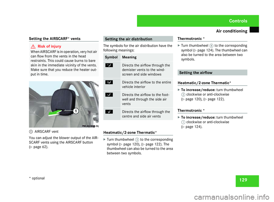
put in time. 1
AIRSCARF vent
You can adjust the blower output of the AIR -
SCARF vents using the AIRSCARF button
( Y page 62). Setting the air distribution
The symbols for the air distribution have the
following meanings: Symbol Meaning
Z
Directs the airflow through the
demister vents to the wind-
screen and side windows
b
Directs the airflow to the entire
vehicle interior
Y
Directs the airflow to the foot-
well and through the side ai
r
vents a
Directs the airflow through the
centre and side air vents
Heatmatic/2-zone Thermatic
* X
Turn thumbwheel 3to the corresponding
symbol (Y page 120), (Y page 122). The
thumbwheel can also be turned to the area
between two symbols. Thermotronic
* X
Turn thumbwheel 8to the corresponding
symbol (Y page 124). The thumbwheel can
also be turned to the area between two
symbols. Setting the airflow
Heatmatic/2-zone Thermatic* X
To increase/reduce: turn thumbwheel
2 clockwise or anti-clockwise
( Y page 120), (Y page 122).
Thermotronic * X
To increase/reduce: turn thumbwheel
1 clockwise or anti-clockwise
( Y page 124). Controls
* optional
171_AKB; 3; 4, en-GB
vpfaff7,
2007-11-13T10:50:25+01:00 - Seite 129
Page 152 of 273
Refuelling
14
9
When you open or close the vehicle with the
key, the fuel filler flap is automatically
unlocked or locked.
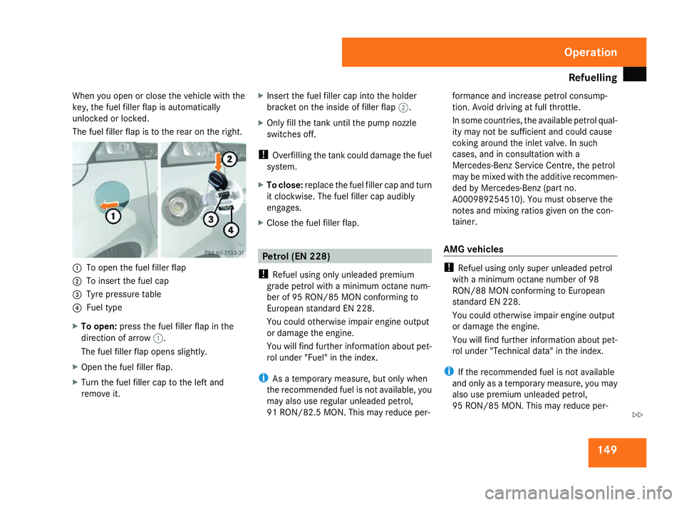
The fuel filler flap is to the rear on the right. 1
To open the fuel filler flap
2 To insert the fuel cap
3 Tyre pressure table
4 Fuel typ e
X To open: press the fuel filler flap in the
direction of arrow 1.
The fuel filler flap opens slightly.
X Open the fuel filler flap.
X Turn the fuel filler cap to the left and
remove it. X
Insert the fuel filler cap into the holder
bracket on the inside of filler flap 2.
X Only fill the tank until the pump nozzle
switches off.
! Overfilling the tank could damage the fuel
system.
X To close: replace the fuel filler cap and tur n
it clockwise. The fuel filler cap audibly
engages.
X Close the fuel filler flap. Petrol (EN 228)
! Refuel using only unleaded premium
grade petrol with a minimum octane num -
ber of 95 RON/85 MON conforming to
European standard EN 228 .
You could otherwise impair engine output
or damage the engine.
You will find further information about pet-
rol under "Fuel" in the index .
i As a temporary measure, but only when
the recommended fuel is not available, yo u
may also use regular unleaded petrol,
91 RON/82.5 MON. This may reduce per- formance and increase petrol consump-
tion. Avoid driving at full throttle.
In some countries, the available petrol qual-
ity may not be sufficient and could caus
e
coking around the inlet valve. In such
cases, and in consultation with a
Mercedes-Benz Service Centre, the petrol
may be mixed with the additive recommen-
ded by Mercedes-Benz (part no.
A000989254510). You must observe the
notes and mixing ratios given on the con -
tainer.
AMG vehicle s !
Refuel using only super unleaded petrol
with a minimum octane number of 98
RON/88 MON conforming to European
standard EN 228.
You could otherwise impair engine output
or damage the engine.
You will find further information about pet-
rol under "Technical data" in the index.
i If the recommended fuel is not available
and only as a temporary measure, you may
also use premium unleaded petrol,
95 RON/85 MON. This may reduce per- Operation
171_AKB; 3; 4, en-GB
vpfaff7,
2007-11-13T10:50:25+01:00 - Seite 149 Z
Page 157 of 273
Engine compartment
154 Coolan
t G
Risk of injury
The cooling system is pressurised. There-
fore, only unscrew the cap once the engine
has cooled down. The coolant temperature
gauge must display less than 70°C. Yo u
could otherwise be scalded by escaping hot
coolant.
Coolant consists of water and antifreeze/cor-
rosion inhibitor. Only check the coolant level
when the vehicle is on a level surface and the
engine has cooled down. Checking the coolant leve
l The expansion tank is located in the engine
compartment on the right-hand side of the
vehicle when viewed in the direction of travel.
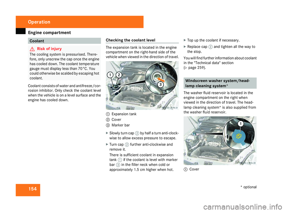
1
Expansion tank
2 Cove r
3 Marker bar
X Slowly turn cap 2by half a turn anti-clock -
wise to allow excess pressure to escape.
X Turn cap 2further anti-clockwise and
remove it.
There is sufficient coolant in expansion
tank 1if the coolant is level with marker
bar 3in the filler neck when cold or
approximately 1.5 cm higher when hot .X
Top up the coolant if necessary.
X Replace cap 2and tighten all the way to
the stop.
You will find further information about coolan t
in the "Technical data" section
( Y page 259). Windscreen washer system/head-
lamp cleaning system
*
The washer fluid reservoir is located in the
engine compartment on the right when
viewed in the direction of travel. The head-
lamp cleaning system* is also supplied from
the washer fluid reservoir. 1
Cove r Operation
* optional
171_AKB; 3; 4, en-GB
vpfaff7,
2007-11-13T10:50:25+01:00 - Seite 154
Page 176 of 273
Where will I find...?
173
6
Valve extractor
7 Electric air pump
Vehicles with a collapsible spare
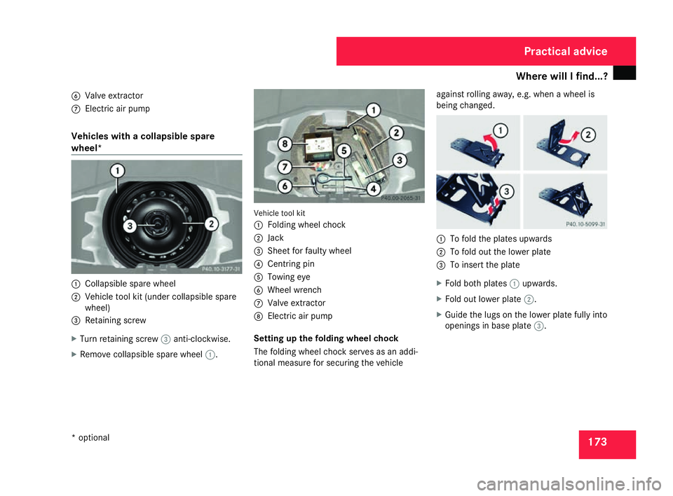
wheel* 1
Collapsible spare wheel
2 Vehicle tool kit (under collapsible spare
wheel)
3 Retaining screw
X Turn retaining screw 3anti-clockwise.
X Remove collapsible spare wheel 1. Vehicle tool kit
1
Folding wheel chock
2 Jack
3 Sheet for faulty wheel
4 Centring pin
5 Towing eye
6 Wheel wrenc h
7 Valve extractor
8 Electric air pump
Setting up the folding wheel choc k
The folding wheel chock serves as an addi-
tional measure for securing the vehicle against rolling away, e.g. when a wheel is
being changed.
1
To fold the plates upwards
2 To fold out the lower plate
3 To insert the plate
X Fold both plates 1upwards.
X Fold out lower plate 2.
X Guide the lugs on the lower plate fully int o
openings in base plate 3. Practical advice
* optional
171_AKB; 3; 4, en-GB
vpfaff7,
2007-11-13T10:50:25+01:00 - Seite 173
Page 213 of 273
Locking/unlocking in an emergency
210 Locking/unlocking in an emergency
Emergency key
If the vehicle can no longer be locked or
unlocked with the key, use the emergency
key element.
If you use the emergency key element to
unlock and open the driver's door or the boot
lid, the anti-theft alarm system* will be trig-
gered (Y page 52).
There are several ways to turn off the alarm:
X Press the korj button on the key.
or
X Insert the key into the ignition lock. Releasing and removing the emergency
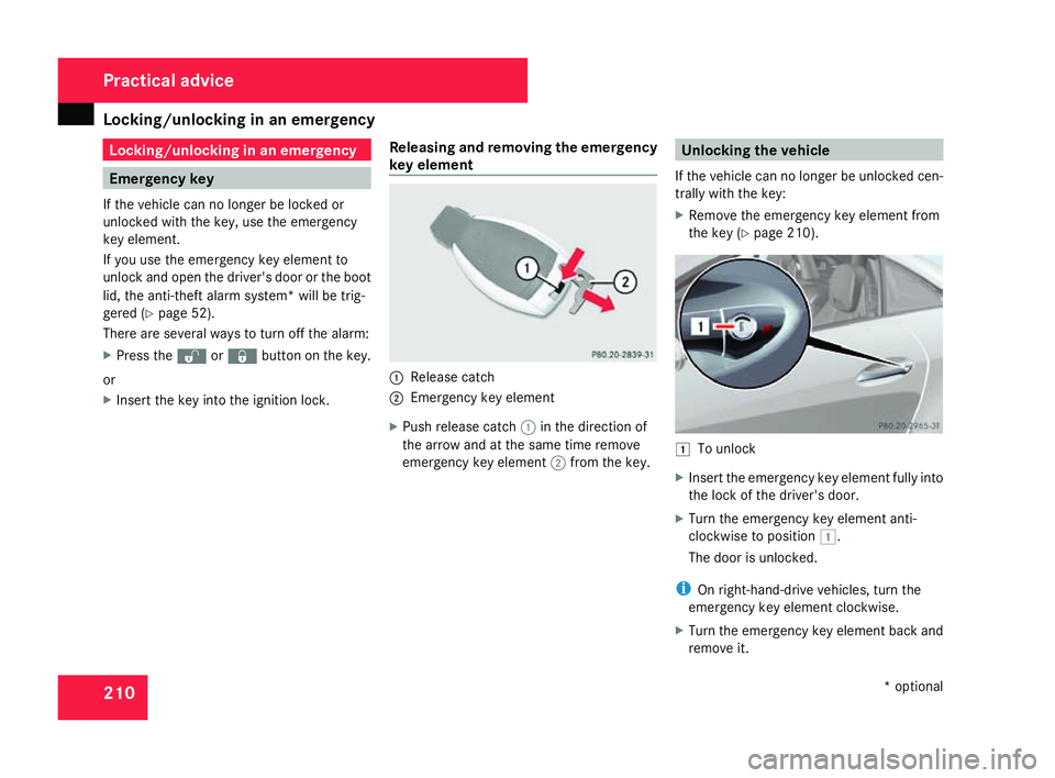
key element 1
Release catch
2 Emergency key element
X Push release catch 1in the direction of
the arrow and at the same time remove
emergency key element 2from the key. Unlocking the vehicle
If the vehicle can no longer be unlocked cen-
trally with the key:
X Remove the emergency key element from
the key (Y page 210). $
To unlock
X Insert the emergency key element fully into
the lock of the driver's door.
X Turn the emergency key element anti-
clockwise to position $.
The door is unlocked.
i On right-hand-drive vehicles, turn the
emergency key element clockwise.
X Turn the emergency key element back and
remove it. Practical advice
* optional
171_AKB; 3; 4, en-GB
vpfaff7,
2007-11-13T10:50:25+01:00 - Seite 210
Page 214 of 273
Locking/unlocking in an emergency
211Locking the vehicle
If the vehicle can no longer be locked cen -
trally with the key :
X Open the driver's door.
X Close the front-passenger door and th e
boot lid.
X Press the central locking button
(Y page 57).
X Check whether the locking knob on th e
front-passenger door is still visible. Press
down the locking knob by hand if neces-
sary .
X Remove the emergency key element from
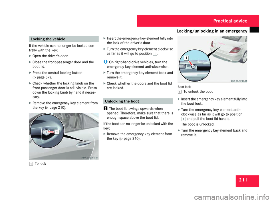
the key (Y page 210). $
To lock X
Insert the emergency key element fully into
the lock of the driver's door.
X Turn the emergency key element clockwise
as far as it will go to position $.
i On right-hand-drive vehicles, turn the
emergency key element anti-clockwise .
X Turn the emergency key element back and
remove it.
X Check whether the doors and the boot lid
are locked. Unlocking the boot
! The boot lid swings upwards when
opened. Therefore, make sure that there is
enough space above the boot lid.
If the boot can no longer be unlocked with th e
key :
X Remove the emergency key element from
the key (Y page 210). Boot lock
$
To unlock the boot
X Insert the emergency key element fully into
the boot lock.
X Turn the emergency key element anti-
clockwise as far as it will go to position
$ and pull the boot lid handle.
The boot is unlocked.
X Turn the emergency key element back and
remove it. Practical advice
171_AKB; 3; 4, en-GB
vpfaff7,
2007-11-13T10:50:25+01:00 - Seite 211