run flat MERCEDES-BENZ SLK ROADSTER 2008 Owners Manual
[x] Cancel search | Manufacturer: MERCEDES-BENZ, Model Year: 2008, Model line: SLK ROADSTER, Model: MERCEDES-BENZ SLK ROADSTER 2008Pages: 273, PDF Size: 4.42 MB
Page 9 of 273
6
Emergency running mod
e
Automatic transmission . . . . . . . . .203
Emergency unlocking
Boot . . . . . . . . . . . . . . . . . . . . . . . .211
Vehicle . . . . . . . . . . . . . . . . . . . . . .210
Engine
Display message . . . . . . . . . . . . . .187
Running irregularl y.. . . . . . . . . . . .201
Starting problems . . . . . . . . . . . . .201
Starting with the key . . . . . . . . . . . .81
Technical data . . . . . . . . . . . . . . . .244
Engine diagnostic warning lamp . ..1 95
Engine electronics . . . . . . . . . . . . . ..241
Malfunction . . . . . . . . . . . . . . . . . .201
Engine number . . . . . . . . . . . . . . . . . .243
Engine oil . . . . . . . . . . . . . . . . . . . . . .258
Checking the oil level (dipstick) . . .153
Checking the oil level (on-board
computer) . . . . . . . . . . . . . . . . . . .152
Consumption . . . . . . . . . . . . . . . . .151
Display message . . . . . . . . . . . . . . . . . . .152, 186, 187
Filler neck . . . . . . . . . . . . . . . . . . .153
Temperature display (on-board
computer) . . . . . . . . . . . . . . . . . . . .96
Topping up . . . . . . . . . . . . . . . . . . .153
ESP ®
(Electronic Stability Program) .51
Activating/deactivating . . . . . . . . . .51
Display message . . . . . . . . . .176, 177
Warning lamp . . . . . . . . . . . . . .51, 194 Exterior lighting
Delayed switch-off (on-board
computer) . . . . . . . . . . . . . . . . . . .105
Exterior mirror parking position
Storing . . . . . . . . . . . . . . . . . . . .67, 69
Exterior mirrors
Adjusting . . . . . . . . . . . . . . . . . . . . .66
Anti-dazzle mode (automatic) . . . . .67
Folding in/out (automatically ).. . . .66
Folding in/out (electrically) . . . . . . .66
Folding in when locking (on-board
computer) . . . . . . . . . . . . . . . . . . .106
Malfunction . . . . . . . . . . . . . . . . . .206
Parking position . . . . . . . . . . . . .67, 69
Resetting . . . . . . . . . . . . . . . . . . . . .66
Storing settings . . . . . . . . . . . . . . . .68
Exterior view
Overview . . . . . . . . . . . . . . . . . . . . .18 F
Fire extinguishe r. . . . . . . . . . . . . . . .174
First-aid kit . . . . . . . . . . . . . . . . . . . . .174
Flat tyre Preparing the vehicle . . . . . . . . . . .218
TIREFIT kit . . . . . . . . . . . . . . . . . . .219
Floormat . . . . . . . . . . . . . . . . . . . . . . .146
Foglamps Display message . . . . . . . . . . . . . .185
Fording . . . . . . . . . . . . . . . . . . . . . . . .164 Frequencies
Garage door opene r.. . . . . . . . . . .262
Telephone . . . . . . . . . . . . . . . . . . .242
Front airbag . . . . . . . . . . . . . . . . . . . . .42
Front-passenger airbag . . . . . . . . . . ..42
Fuel . . . . . . . . . . . . . . . . . . . . . . . . . . .255
Loss . . . . . . . . . . . . . . . . . . . . . . . .200
Petrol . . . . . . . . . . . . . . . . . . . . . . .149
Fuel consumptio n. . . . . . . . . . .256, 257
Fuel filler flap Opening/closing . . . . . . . . . . . . . .148
Fuel lin e
Malfunction . . . . . . . . . . . . . . . . . .200
Fuel tank
Malfunction . . . . . . . . . . . . . . . . . .200
Fuse allocation chart . . . . . . . . . . ..237
Fuse box Boot . . . . . . . . . . . . . . . . . . . . . . . .238
Dashboard . . . . . . . . . . . . . . . . . . .238
Engine compartment . . . . . . . . . . .238
Fuse s. . . . . . . . . . . . . . . . . . . . . . . . . .237 G
Garage door Opening/closing (with the remote
control) . . . . . . . . . . . . . . . . . . . . .145
Garage door opener . . . . . . . . . . . . ..144
Clearing the memory . . . . . . . . . . .146 Index
171_AKB; 3; 4, en-GB
vpfaff7,
2007-11-13T10:50:25+01:00 - Seite
6
Page 42 of 273
Occupant safet
y 39In particular, work relevant to safety or on
safety-related systems must be carried out
at a qualified specialist workshop. If this
work is not carried out correctly, the oper-
ating safety of your vehicle may be affec -
ted. There is a risk of an accident and injury .SRS (Supplemental Restraint System)
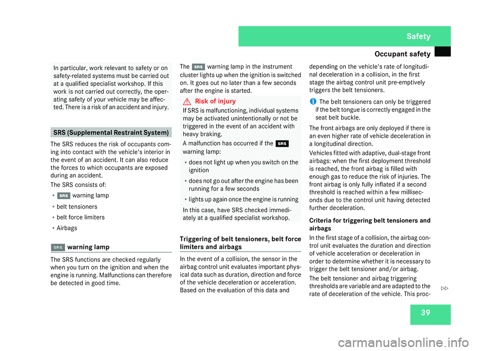
The SRS reduces the risk of occupants com-
ing into contact with the vehicle's interior in
the event of an accident. It can also reduce
the forces to which occupants are exposed
during an accident.
The SRS consists of:
R 1 warning lamp
R belt tensioner s
R belt force limiters
R Airbag s
11 warning lam p The SRS functions are checked regularly
when you turn on the ignition and when the
engine is running. Malfunctions can therefore
be detected in good time. The
1 warning lamp in the instrumen t
cluster lights up when the ignition is switched
on. It goes out no later than a few seconds
after the engine is started. G
Risk of injury
If SRS is malfunctioning, individual systems
may be activated unintentionally or not be
triggered in the event of an accident with
heavy braking.
A malfunction has occurred if the 1
warning lamp:
R does not light up when you switch on the
ignition
R does not go out after the engine has been
running for a few seconds
R lights up again once the engine is running
In this case, have SRS checked immedi-
ately at a qualified specialist workshop.
Triggering of belt tensioners, belt force
limiters and airbags In the event of a collision, the sensor in the
airbag control unit evaluates important phys-
ical data such as duration, direction and force
of the vehicle deceleration or acceleration.
Based on the evaluation of this data anddepending on the vehicle's rate of longitudi-
nal deceleration in a collision, in the firs
t
stage the airbag control unit pre-emptively
triggers the belt tensioners.
i The belt tensioners can only be triggered
if the belt tongue is correctly engaged in the
seat belt buckle.
The front airbags are only deployed if there is
an even higher rate of vehicle deceleration in
a longitudinal direction .
Vehicles fitted with adaptive, dual-stage front
airbags: when the first deployment threshold
is reached, the front airbag is filled with
enough gas to reduce the risk of injuries. The
front airbag is only fully inflated if a second
threshold is reached within a few millisec-
onds due to the control unit having detected
further deceleration.
Criteria for triggering belt tensioners and
airbags
In the first stage of a collision, the airbag con-
trol unit evaluates the duration and direction
of vehicle acceleration or deceleration in
order to determine whether it is necessary to
trigger the belt tensioner and/or airbag.
The belt tensioner and airbag triggering
thresholds are variable and are adapted to the
rate of deceleration of the vehicle. This proc- Safety
171_AKB; 3; 4, en-GB
vpfaff7,
2007-11-13T10:50:25+01:00 - Seite 39 Z
Page 158 of 273
Tyres and wheels
15
5
X
Add windscreen washer concentrate to the
washer fluid all year round. G
Risk of fire
Windscreen washer concentrate is highly
flammable. Fire, naked flames and smoking
are prohibited when windscreen washe r
concentrate is being handled.
Use
R a windscreen washer fluid additive
such as MB Summerwash to preven t
smearing (for temperatures above freez-
ing).
R a windscreen washer fluid additive wit h
antifreeze properties such as MB Winter-
wash (if there is a risk of frost).
X Mix the windscreen washer fluid in a con-
tainer beforehand. Adapt the mixing ratio
to the outside temperatures.
! Only use windscreen washer fluid which
is suitable for plastic lamp lenses. Unsuit-
able windscreen washer fluid could dam-
age the plastic lamp lenses of the head-
lamps. X
To open: pull cap1upwards by the tab .
X To close: press cap 1onto the filler neck
until it clicks into place. Tyres and wheels
Points to remember
! For safety reasons, Mercedes-Benz rec-
ommends that you only use tyres and
wheels which have been approved by
Mercedes-Benz specifically for your vehi-
cle. These tyres have been specially adap-
ted for use with the control systems, such
as ABS or ESP ®
, and are marked as follows:
R MO = Mercedes-Benz Original
R MOE = Mercedes-Benz Original Extended
(with run-flat characteristics)*
Mercedes-Benz Original Extended tyres*
should only be used on wheels that have
been specifically approved by Mercedes-
Benz.
If you use other tyres and wheels,
Mercedes-Benz cannot accept any respon-
sibility for damage that may result from
this. Further information about tyres,
wheels and approved combinations can be
obtained from any Mercedes-Benz Service
Centre.
If you use tyres other than those tested and
recommended for Mercedes-Benz vehi-
cles, characteristics such as handling, vehi-
cle noise emissions and fuel consumption Operation
* optional
171_AKB; 3; 4, en-GB
vpfaff7,
2007-11-13T10:50:25+01:00 - Seite 155 Z
Page 162 of 273
Tyres and wheels
15
9
message will appear in the multi-function dis-
play.
The function of the tyre pressure loss warning
system is limited or delayed if:
R snow chains are fitted to your vehicle's
tyres
R road conditions are wintry
R you are driving on sand or grave l
R you adopt a very sporty driving style (cor -
nering at high speeds or driving with high
rates of acceleration)
R you are driving with a heavy load (in th e
vehicle or on the roof)
Restarting the tyre pressure loss warn-
ing system Restart the tyre pressure loss warning system
if you have :
R changed the tyre pressure
R changed the wheels or tyre s
R fitted new wheels or tyres
X Before restarting, consult the table of tyre
pressures on the inside of the fuel filler fla p
to ensure that the tyre pressure in all fou rtyres is set correctly for the operating con-
ditions concerned
.
X Also observe the notes in the section on
tyre pressures (Y page 157). G
Risk of accident
The tyre pressure loss warning system can
only give reliable warnings if you have set
the correct tyre pressure.
If an incorrect tyre pressure is set, thes e
incorrect values will be monitored.
A tyre with insufficient pressure results in
an instability of the vehicle when driving,
thus increasing the risk of an accident .
X Make sure that the key is in position 2in
the ignition lock .
The standard display appears in the multi-
function display (Y page 95).
X Press korj to select the tyre pres-
sure function:
Run Flat Indicator active
Menu: R-Button æ
X Press the reset button on the left of the
instrument cluster.
The following message appears in the
multi-function display:
Restart Run Flat Indicator ?Yes Cancel
If you wish to confirm the restart:
X Press the æbutton.
The following message appears in the
multi-function display:
Run Flat Indicator restarted
After a teach-in period, the tyre pressure
loss warning system will monitor the set
tyre pressures of all four tyres.
If you wish to cancel the restart:
X Press the çbutton.
or
X Wait until the message
Restart Run Flat Indicator?
Yes Cancel disappears.
The tyre pressure values stored at the last
restart will continue to be monitored. Operation
171_AKB; 3; 4, en-GB
vpfaff7
, 2007-11-13T10:50:25+01:00 - Seite 159
Page 181 of 273
Display
messages 17
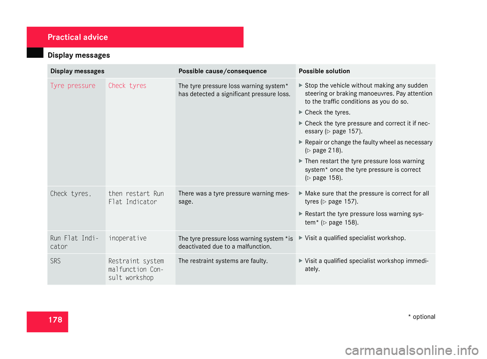
8 Display messages Possible cause/consequence Possible solution
Tyre pressure Check tyres
The tyre pressure loss warning system*
has detected a significant pressure loss. X
Stop the vehicle without making any sudden
steering or braking manoeuvres. Pay attention
to the traffic conditions as you do so.
X Check the tyres.
X Check the tyre pressure and correct it if nec-
essary (Y page 157).
X Repair or change the faulty wheel as necessar y
( Y page 218).
X Then restart the tyre pressure loss warning
system* once the tyre pressure is correc t
( Y page 158). Check tyres, then restart Run
Flat Indicator There was a tyre pressure warning mes-
sage. X
Make sure that the pressure is correct for all
tyres (Y page 157).
X Restart the tyre pressure loss warning sys-
tem* (Y page 158). Run Flat Indi-
cator inoperative
The tyre pressure loss warning system
*is
deactivated due to a malfunction . X
Visit a qualified specialist workshop. SRS Restraint system
malfunction Con-
sult workshop The restraint systems are faulty. X
Visit a qualified specialist workshop immedi-
ately. Practical advice
* optional
171_AKB; 3; 4, en-GB
vpfaff7,
2007-11-13T10:50:25+01:00 - Seite 178
Page 221 of 273
Flat tyre
218 Removin
g
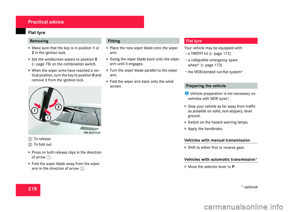
X Make sure that the key is in position 1or
2 in the ignition lock .
X Set the windscreen wipers to position II
( Y page 78) on the combination switch.
X When the wiper arms have reached a ver-
tical position, turn the key to position 0and
remove it from the ignition lock. 1
To release
2 To fold out
X Press on both release clips in the direction
of arrow 1.
X Fold the wiper blade away from the wipe r
arm in the direction of arrow 2. Fitting
X Place the new wiper blade onto the wiper
arm.
X Swing the wiper blade back onto the wipe r
arm until it engages.
X Turn the wiper blade parallel to the wiper
arm.
X Fold the wiper arm back onto the wind-
screen. Flat tyre
Your vehicle may be equipped with:
R a TIREFIT kit (Y page 172)
R a collapsible emergency spare
wheel* (Y page 173)
R the MOExtended run-flat system* Preparing the vehicle
i Vehicle preparation is not necessary on
vehicles with MOE tyres*.
X Stop your vehicle as far away from traffi c
as possible on solid, non-slippery, level
ground.
X Switch on the hazard warning lamps.
X Apply the handbrake.
Vehicles with manual transmissio n X
Shift to either first or reverse gear .
Vehicles with automatic transmission* X
Move the selector lever to P. Practical advice
* optional
171_AKB; 3; 4, en-GB
vpfaff7,
2007-11-13T10:50:25+01:00 - Seite 218
Page 224 of 273
Flat tyre
221
X
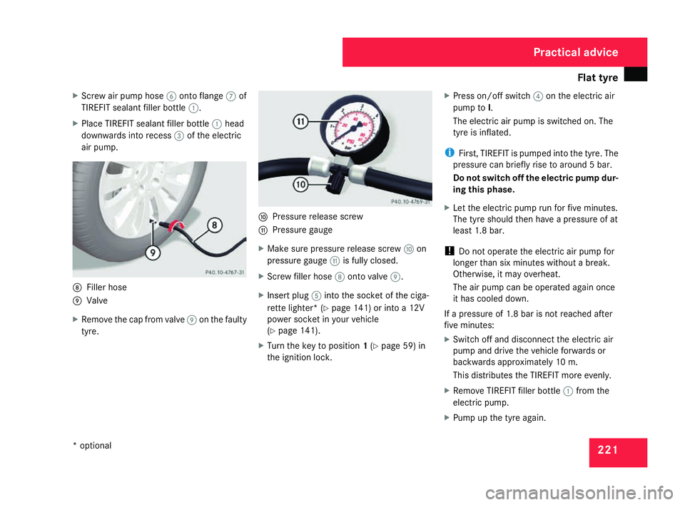
Screw air pump hose 6onto flange 7of
TIREFIT sealant filler bottle 1.
X Place TIREFIT sealant filler bottle 1head
downwards into recess 3of the electric
air pump. 8
Filler hos e
9 Valve
X Remove the cap from valve 9on the faulty
tyre. a
Pressure release screw
b Pressure gauge
X Make sure pressure release screw aon
pressure gauge bis fully closed.
X Screw filler hose 8onto valve 9.
X Insert plug 5into the socket of the ciga-
rette lighter* (Y page 141) or into a 12V
power socket in your vehicle
( Y page 141).
X Turn the key to position 1(Y page 59) in
the ignition lock. X
Press on/off switch 4on the electric air
pump to I.
The electric air pump is switched on. The
tyre is inflated.
i First, TIREFIT is pumped into the tyre. The
pressure can briefly rise to around 5 bar.
Do not switch off the electric pump dur-
ing this phase.
X Let the electric pump run for five minutes.
The tyre should then have a pressure of at
least 1.8 bar.
! Do not operate the electric air pump for
longer than six minutes without a break.
Otherwise, it may overheat.
The air pump can be operated again once
it has cooled down.
If a pressure of 1.8 bar is not reached after
five minutes:
X Switch off and disconnect the electric ai r
pump and drive the vehicle forwards or
backwards approximately 10 m.
This distributes the TIREFIT more evenly.
X Remove TIREFIT filler bottle 1from the
electric pump.
X Pump up the tyre again. Practical advice
* optional
171_AKB; 3; 4, en-GB
vpfaff7,
2007-11-13T10:50:25+01:00 - Seite 221
Page 226 of 273
Flat tyre
223
Version
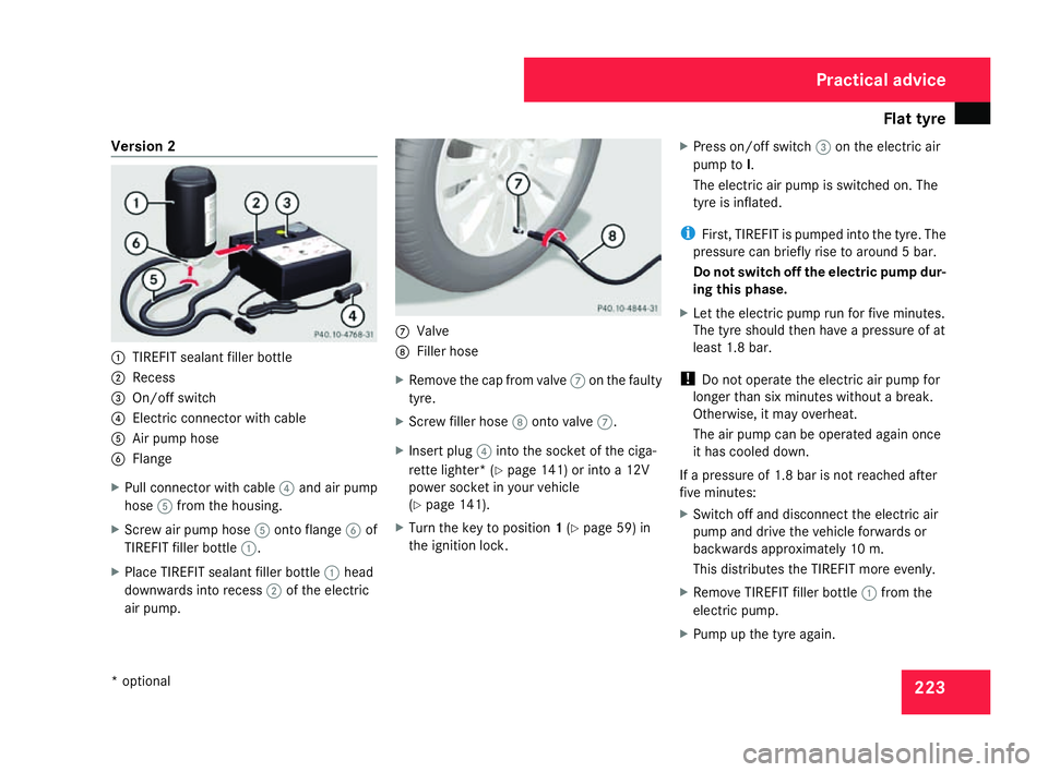
2 1
TIREFIT sealant filler bottle
2 Recess
3 On/off switch
4 Electric connector with cable
5 Air pump hos e
6 Flange
X Pull connector with cable 4and air pump
hose 5from the housing.
X Screw air pump hose 5onto flange 6of
TIREFIT filler bottle 1.
X Place TIREFIT sealant filler bottle 1head
downwards into recess 2of the electric
air pump. 7
Valve
8 Filler hos e
X Remove the cap from valve 7on the faulty
tyre.
X Screw filler hose 8onto valve 7.
X Insert plug 4into the socket of the ciga-
rette lighter* (Y page 141) or into a 12V
power socket in your vehicle
( Y page 141).
X Turn the key to position 1(Y page 59) in
the ignition lock . X
Press on/off switch 3on the electric air
pump to I.
The electric air pump is switched on. The
tyre is inflated.
i First, TIREFIT is pumped into the tyre. The
pressure can briefly rise to around 5 bar.
Do not switch off the electric pump dur-
ing this phase .
X Let the electric pump run for five minutes.
The tyre should then have a pressure of at
least 1.8 bar.
! Do not operate the electric air pump for
longer than six minutes without a break.
Otherwise, it may overheat.
The air pump can be operated again once
it has cooled down.
If a pressure of 1.8 bar is not reached after
five minutes:
X Switch off and disconnect the electric ai r
pump and drive the vehicle forwards or
backwards approximately 10 m.
This distributes the TIREFIT more evenly.
X Remove TIREFIT filler bottle 1from the
electric pump .
X Pump up the tyre again. Practical advice
* optional
171_AKB; 3; 4, en-GB
vpfaff7
, 2007-11-13T10:50:25+01:00 - Seite 223
Page 249 of 273
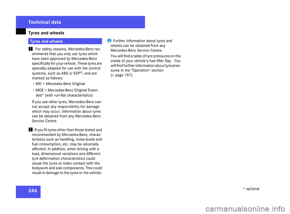
Tyres and wheels
24
6 Tyres and wheels
! For safety reasons, Mercedes-Benz rec-
ommends that you only use tyres which
have been approved by Mercedes-Benz
specifically for your vehicle. These tyres ar e
specially adapted for use with the control
systems, such as ABS or ESP ®
, and are
marked as follows:
R MO = Mercedes-Benz Original
R MOE = Mercedes-Benz Original Exten-
ded* (with run-flat characteristics)
If you use other tyres, Mercedes-Benz can-
not accept any responsibility for damage
which may occur. Information about tyres
can be obtained from any Mercedes-Ben z
Service Centre.
! If you fit tyres other than those tested and
recommended by Mercedes-Benz, charac-
teristics such as handling, noise levels and
fuel consumption, etc. may be adversel y
affected. In addition, when driving with a
load, dimensional variations and differen t
tyre deformation characteristics could
cause the tyres to make contact with the
bodywork and axle components. This could
result in damage to the tyres or the vehicle. i
Further information about tyres and
wheels can be obtained from any
Mercedes-Benz Service Centre.
You will find a table of tyre pressures on the
inside of your vehicle's fuel filler flap . You
will find further information about tyre pres-
sures in the "Operation" section
( Y page 157). Technical data
* optional
171_AKB; 3; 4, en-GB
vpfaff7,
2007-11-13T10:50:25+01:00 - Seite 246
Page 250 of 273
Tyres and wheels
24
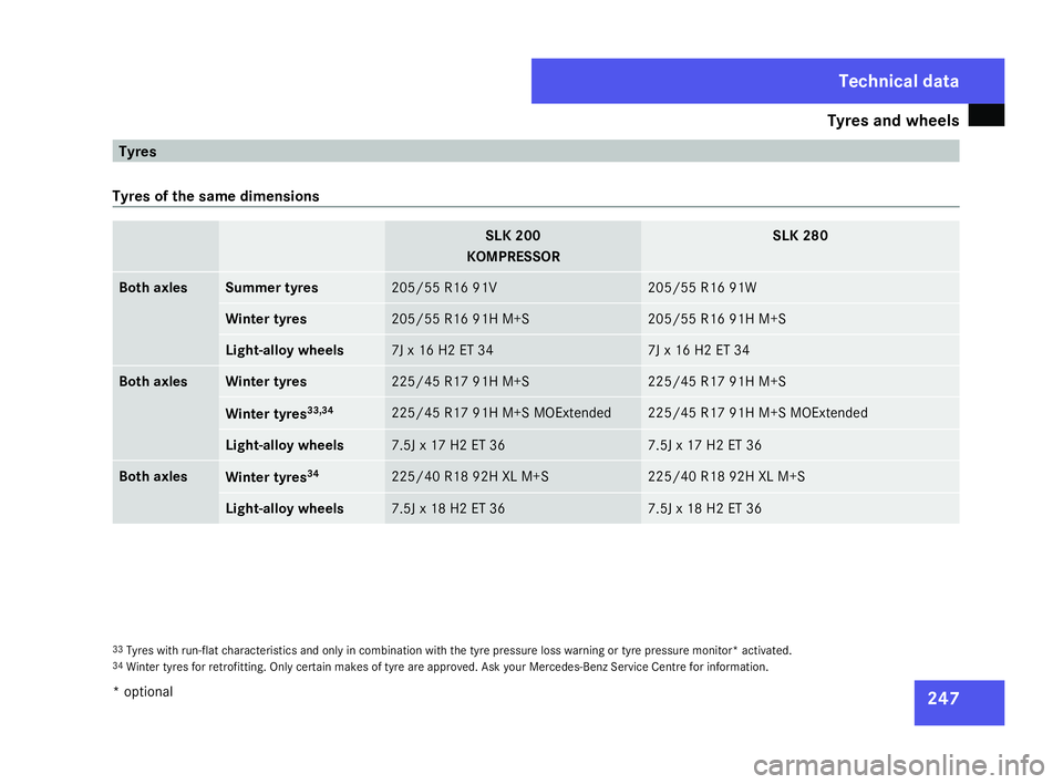
7 Tyre
s
Tyres of the same dimensions SLK 20
0
KOMPRESSOR SLK 280
Both axles Summer tyres 205/55 R16 91
V 205/55 R16 91W
Winter tyres 205/55 R16 91H M+S 205/55 R16 91H M+S
Light-alloy wheels 7J x 16 H2 ET 34 7J x 16 H2 ET 34
Both axle
s Winter tyres 225/45 R17 91H M+S 225/45 R17 91H M+S
Winter tyres
33,34 225/45 R17 91H M+S MOExtended 225/45 R17 91H M+S MOExtended
Light-alloy wheels 7.5J x 17 H2 ET 36 7.5J x 17 H2 ET 36
Both axle
s Winter tyres
34 225/40 R18 92H XL M+S 225/40 R18 92H XL M+S
Light-alloy wheels 7.5J x 18 H2 ET 36 7.5J x 18 H2 ET 36
33
Tyres with run-flat characteristics and only in combination with the tyre pressure loss warning or tyre pressure monitor* activated.
34 Winter tyres for retrofitting. Only certain makes of tyre are approved. Ask your Mercedes-Benz Service Centre for information. Technical data
* optiona l
171_AKB; 3; 4, en-GB
vpfaff7,
2007-11-13T10:50:25+01:00 - Seite 247