set clock MERCEDES-BENZ SLK350 2010 R171 Owner's Manual
[x] Cancel search | Manufacturer: MERCEDES-BENZ, Model Year: 2010, Model line: SLK350, Model: MERCEDES-BENZ SLK350 2010 R171Pages: 312, PDF Size: 5.75 MB
Page 8 of 312
Clear button .......................................
116
Climate control see Climate control system
Climate control system ....................162
Air conditioning ............................. 165
Air conditioning refrigerant ............ 303
Air distribution ............................... 168
Air recirculation mode ................... 169
Air vents ........................................ 166
Air volume ..................................... 168
Automatic mode ............................ 166
Deactivating system ......................165
Front defroster .............................. 168
Maximum cooling MAX COOL ........169
Residual heat and ventilation ......... 169
Temperature .................................. 166
Clock ...................................... 26, 93, 105
Cockpit ................................................. 25
Cold tire inflation pressure ..............217
Collapsible tire (spare wheel) ..........300
Collapsible wheel chock ...................234
COMAND system see separate COMAND system
operating instructions
Combination switch ............................73
Control system .................................... 93
Multifunction display .......................95
Multifunction steering wheel ............ 94
Resetting to factory settings .......... 102
Control system menus ........................ 96
AMG ................................................. 97
Audio/DVD .................................... 100
Navigation ..................................... 101
Settings ......................................... 102
Standard display .............................. 96
Telephone ...................................... 110
Trip computer ................................ 109
Vehicle status message memory ...101
Control system submenus
Convenience .................................. 108
Instrument cluster .........................103
Lighting .......................................... 105
Time/Date ..................................... 105
Vehicle ........................................... 108
Convenience submenu
Easy-entry/exit feature .................. 108 Coolant
Anticorrosion/antifreeze ...............305
Capacities ...................................... 301
Checking level ............................... 196
Messages in the multifunction
display ........................................... 247
Corner-illuminating front fog
lamps .................................................... 75
Cruise control .................................... 159
Activating ....................................... 160
Canceling ....................................... 160
Changing the set speed .................161
Last stored speed .......................... 161
Lever .............................................. 160
Messages in the multifunction
display ........................................... 241
Resume function ............................ 161
Setting current speed .................... 160
Cup holders ........................................ 176
Curb weight ....................................... 217
Customer Assistance Center (CAC) ...21
Customer Relations Department .......21 D
Dashboard see Instrument cluster
Data recording ..................................... 21
Date, Setting ...................................... 105
Daytime running lamp mode ..............72
Switching on or off ......................... 106
Deep water
see Standing water
Defogging (windshield) .....................169
Defroster Front (Climate control system) ......168
Rear window .................................. 170
Delayed shut-off
Exterior lamps ................................ 107
Interior lighting .............................. 107
Department of Transportation
see DOT
Difficulties
While driving .................................... 82
With starting .................................... 80
Digital speedometer ............................ 97
Dimensions (vehicle) see Vehicle specification 6
Index 171_AKB; 3; 60, en-US
d2ureepe,
Version: 2.11.8.1 2009-05-11T16:00:23+02:00 - Seite 6
Page 28 of 312
Instrument cluster
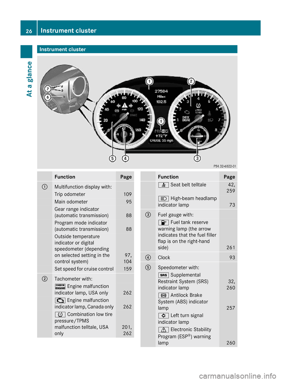
Function Page
:
Multifunction display with:
Trip odometer 109
Main odometer 95
Gear range indicator
(automatic transmission)
88
Program mode indicator
(automatic transmission)
88
Outside temperature
indicator or digital
speedometer (depending
on selected setting in the
control system)
97,
104 Set speed for cruise control 159
;
Tachometer with:
! Engine malfunction
indicator lamp, USA only
262
; Engine malfunction
indicator lamp, Canada only
262
h Combination low tire
pressure/TPMS
malfunction telltale, USA
only
201,
262 Function Page
7 Seat belt telltale 42,
259 K High-beam headlamp
indicator lamp
73
=
Fuel gauge with:
8 Fuel tank reserve
warning lamp (the arrow
indicates that the fuel filler
flap is on the right-hand
side)
261
?
Clock 93
A
Speedometer with:
+ Supplemental
Restraint System (SRS)
indicator lamp
32,
260 ! Antilock Brake
System (ABS) indicator
lamp
257
# Left turn signal
indicator lamp
d Electronic Stability
Program (ESP
®
) warning
lamp 26026
Instrument clusterAt a glance
171_AKB; 3; 60, en-US
d2ureepe,
Version: 2.11.8.1 2009-05-11T16:00:23+02:00 - Seite 26
Page 95 of 312
Activating the instrument cluster
The instrument cluster is activated when you
R open the driver’s door
R switch on the ignition
R press reset button .
R switch on the exterior lamps
i Opening the driver’s door or pressing the
reset button . without switching on the
ignition or the exterior lamps activates the
instrument cluster illumination only for
30 seconds. Adjusting the instrument cluster
illumination
X To brighten illumination: Press knob :
briefly.
X To dim illumination: Press knob ;
briefly.
The illumination brightness for the instrument
cluster changes each time you press
knob :
or ;. Several settings are possible.
i The instrument cluster illumination is
dimmed or brightened automatically to suit
ambient light conditions.
You can only adjust the brightness of the
instrument cluster illumination when it is
dark outside.
i With the exterior lighting switched on, the
brightness of the switches in the center
console will also be adjusted when using
knob : or ;. Resetting trip odometer
X Make sure you are viewing the standard
display
(Y page 96) in the multifunction
display.
X Press and hold reset button .
until the trip
odometer is reset. Tachometer
The red marking on the tachometer
(Y
page 26) denotes excessive engine speed.
! Avoid driving at excessive engine speeds,
as it may result in serious engine damage
that is not covered by the Mercedes-Benz
Limited Warranty.
To help protect the engine, the fuel supply is
interrupted if the engine is operated within
the red marking. Clock
In vehicles with the audio system, the clock
can be set via the control system
(Y page 105).
For setting the time with the COMAND
system, see separate COMAND system
operating instructions. Control system
Introduction
The
control system is activated as soon as the
starter switch is in position 1.
The control system enables you to call up
information about your vehicle and to change
vehicle settings.
For example, you can use the control system
to find out when your vehicle is next due for
maintenance service, to set the language for
messages in the instrument cluster display,
and much more. G
Warning!
A driver’s attention to the road and traffic
conditions must always be his/her primary
focus when driving.
For your safety and the safety of others,
selecting features through the multifunction
steering wheel should only be done by the
driver
when traffic and road conditions permit
it to be done safely. Control system
93
Controls in detail
171_AKB; 3; 60, en-US
d2ureepe, Version: 2.11.8.1 2009-05-11T16:00:23+02:00 - Seite 93 Z
Page 168 of 312
The cooling function switches off after a
short delay.
Activating Moist air can fog up the windows. You can
dehumidify the interior air with the air
conditioning.
X
Press button Á 10
/¿ 11
.
The indicator lamp in the button comes on. Automatic mode
The automatic mode is available in vehicles
with automatic climate control only.
When
operating the climate control system in
automatic mode, the interior air temperature,
air volume and air distribution are adjusted
automatically.
In automatic mode, cooling with
dehumidification is switched on. This function
can be switched off if necessary. G
Warning!
If you deactivate the air conditioning, the
vehicle will not be cooled when weather
conditions
are warm. The windows can fog up
more quickly. Window fogging may impair
visibility and endanger you and others.
X Set the desired temperature
(Y page 166).
X Activating: Press button Ã.
The
indicator lamp in the button comes on.
The air volume and air distribution are
adjusted automatically.
X Deactivating: Press button à again.
The indicator lamp in the button goes out.
The air volume changes to level 2 and the
air distribution changes to Q. Setting the temperature
You can adjust the air temperature on each
side of the passenger compartment. You
should
raise or lower the temperature setting
in small increments, preferably starting at
72‡ (22†).
Climate control X
Increasing/decreasing: Turn
temperature control : and/or ?
(Y page 162) slightly clockwise or
counterclockwise.
Automatic climate control X
Increasing/decreasing: Press button
9
or : until the desired temperature
appears in display H (Y page 163). Adjusting air vents
G
Warning!
When operating the climate control, the air
that enters the passenger compartment
through the air vents can be very hot or very
cold
(depending on the set temperature). This
may cause burns or frostbite to unprotected
skin in the immediate area of the air vents.
Always keep sufficient distance between
unprotected parts of the body and the air
vents. If necessary, use the air distribution
adjustment to direct the air to air vents in the
vehicle interior that are not in the immediate
area of unprotected skin.
For best possible performance of the climate
control:
X Keep the air intake grille in front of the
windshield
free of snow, leaves, sticks, and
any other debris.
X Always keep all air vents and grilles in the
passenger compartment free from
obstruction.
10 Vehicles with climate control
11 Vehicles with automatic climate control 166
Climate control system
Controls in detail
171_AKB; 3; 60, en-US
d2ureepe,
Version: 2.11.8.1 2009-05-11T16:00:23+02:00 - Seite 166
Page 170 of 312
Adjusting air distribution
The symbols on the control represent the
following functions: Symbol Function
M
Directs air to the windshield and
through the side defroster air
vents
Q
Directs air into the entire
vehicle interior
O
Directs air to the footwells and
through the side air vents
P
Directs air through the center
and side air vents
Climate control
The air distribution can be adjusted manually.
X
Turn air distribution control =
(Y page 162) to the desired symbol.
The
air distribution is adjusted according to
the chosen setting.
You can also turn the control to a position
between two symbols.
Automatic climate control X
Turn air distribution control D
(Y page 163) to the desired symbol.
The
air distribution is adjusted according to
the chosen setting.
You can also turn the control to a position
between two symbols. Adjusting air volume
Climate control X
Decreasing/increasing: Turn air volume
control ; (Y page 162) clockwise or
counterclockwise. Automatic climate control X
Decreasing/increasing: Turn air volume
control : (Y page 163) clockwise or
counterclockwise. Front defroster
You can use this setting to defrost the
windshield, for example if it is iced up.
You can also defog the windshield and the
door windows.
i Keep this setting selected only until the
windshield or the door windows are clear
again.
X Activating: Press button ¬.
The
indicator lamp in the button comes on.
The climate control switches to the
following functions automatically:
R most efficient blower speed and heating
power, depending on outside
temperature
R air flows onto the windshield and the
door windows (side air vents must be
open)
R the air conditioning compressor
switches on at outside temperatures
above approximately 41‡ (5†) for air-
drying
R the air recirculation mode is switched off
X Deactivating: Press button ¬ again.
The indicator lamp in the button goes out.
The previous settings are once again in
effect.
i The cooling remains switched on. 168
Climate control systemControls in detail
171_AKB; 3; 60, en-US
d2ureepe,
Version: 2.11.8.1 2009-05-11T16:00:23+02:00 - Seite 168
Page 237 of 312
X
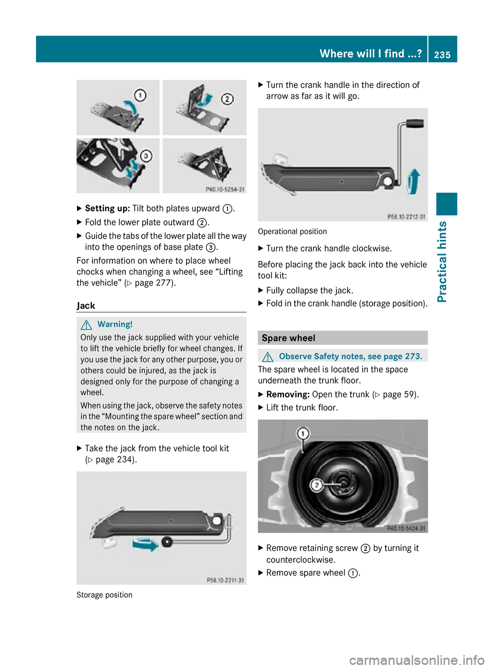
Setting up: Tilt both plates upward :.
X Fold the lower plate outward ;.
X Guide the tabs of the lower plate all the way
into the openings of base plate =.
For information on where to place wheel
chocks when changing a wheel, see “Lifting
the vehicle” ( Y page 277).
Jack G
Warning!
Only use the jack supplied with your vehicle
to lift the vehicle briefly for wheel changes. If
you use the jack for any other purpose, you or
others could be injured, as the jack is
designed only for the purpose of changing a
wheel.
When using the jack, observe the safety notes
in the “Mounting the spare wheel” section and
the notes on the jack.
X Take the jack from the vehicle tool kit
(Y page 234). Storage position X
Turn the crank handle in the direction of
arrow as far as it will go. Operational position
X
Turn the crank handle clockwise.
Before placing the jack back into the vehicle
tool kit:
X Fully collapse the jack.
X Fold in the crank handle (storage position). Spare wheel
G
Observe Safety notes, see page 273.
The spare wheel is located in the space
underneath the trunk floor.
X Removing: Open the trunk (Y page 59).
X Lift the trunk floor. X
Remove retaining screw ; by turning it
counterclockwise.
X Remove spare wheel :. Where will I find ...?
235Practical hints
171_AKB; 3; 60, en-US
d2ureepe, Version: 2.11.8.1 2009-05-11T16:00:23+02:00 - Seite 235 Z
Page 238 of 312
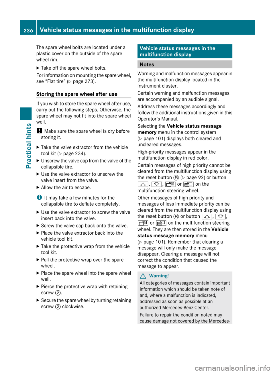
The spare wheel bolts are located under a
plastic cover on the outside of the spare
wheel rim.
X
Take off the spare wheel bolts.
For information on mounting the spare wheel,
see “Flat tire” ( Y page 273).
Storing the spare wheel after use If you wish to store the spare wheel after use,
carry out the following steps. Otherwise, the
spare wheel may not fit into the spare wheel
well.
!
Make sure the spare wheel is dry before
storing it.
X Take the valve extractor from the vehicle
tool kit ( Y page 234).
X Unscrew the valve cap from the valve of the
collapsible tire.
X Use the valve extractor to unscrew the
valve insert from the valve.
X Allow the air to escape.
i It may take a few minutes for the
collapsible tire to deflate completely.
X Use the valve extractor to screw the valve
insert back into the valve.
X Screw the valve cap back onto the valve.
X Place the valve extractor back into the
vehicle tool kit.
X Take the protective wrap from the vehicle
tool kit.
X Pull the protective wrap over the spare
wheel.
X Place the spare wheel into the spare wheel
well.
X Pierce the protective wrap with retaining
screw ;.
X Secure the spare wheel by turning retaining
screw ; clockwise. Vehicle status messages in the
multifunction display
Notes
Warning and malfunction messages appear in
the multifunction display located in the
instrument cluster.
Certain warning and malfunction messages
are accompanied by an audible signal.
Address these messages accordingly and
follow the additional instructions given in this
Operator’s Manual.
Selecting the Vehicle status message
memory menu in the control system
(Y page 101) displays both cleared and
uncleared messages.
High-priority messages appear in the
multifunction display in red color.
Certain messages of high priority cannot be
cleared from the multifunction display using
the reset button . (Y page 92) or button
&, *, U or V on the
multifunction steering wheel.
Other messages of high priority and
messages of less immediate priority can be
cleared from the multifunction display using
the reset button . or button &, *,
U or V on the multifunction steering
wheel. They are then stored in the Vehicle
status message memory menu
(Y page 101). Remember that clearing a
message will only make the message
disappear. Clearing a message will not
correct the condition that caused the
message to appear. G
Warning!
All categories of messages contain important
information which should be taken note of
and, where a malfunction is indicated,
addressed as soon as possible at an
authorized Mercedes-Benz Center.
Failure to repair the condition noted may
cause
damage not covered by the Mercedes- 236
Vehicle status messages in the multifunction display
Practical hints
171_AKB; 3; 60, en-US
d2ureepe,
Version: 2.11.8.1 2009-05-11T16:00:23+02:00 - Seite 236
Page 285 of 312
G
Warning!
Do not place metal objects on the battery as
this could result in a short circuit.
Use
leak-proof batteries only to avoid the risk
of acid burns in the event of an accident.
Take care that you do not become statically
charged, e.g. by wearing synthetic clothing or
rubbing against textiles. For this reason, you
also should not pull or push the battery over
carpets or other synthetic materials.
Never touch the battery first. First touch the
outside body of the vehicle in order to release
any possible electrostatic charges.
Do not rub the battery with rags or cloths. The
battery could explode if touched due to
electrostatic charge or due to spark
formation.
! As any other battery, the battery may
discharge if you do not operate the vehicle
for an extended period of time. Have the
battery disconnected at a qualified
workshop or an authorized Mercedes-Benz
Center in such a case. You may also
connect an accessory battery charge unit
expressly approved by Mercedes-Benz for
your vehicle model to maintain the battery
charge. Contact an authorized Mercedes-
Benz Center for further information.
The battery, the battery ventilation hose
and the lateral plug must always be
securely installed when the vehicle is in
operation.
! Never loosen or detach battery terminal
clamps while the engine is running or the
SmartKey is in the starter switch.
Otherwise the alternator and other
electronic components could be severely
damaged.
Have the battery checked regularly at an
authorized Mercedes-Benz Center.
Refer to Maintenance Booklet for
maintenance intervals or contact an
authorized Mercedes-Benz Center for
further information. i
After battery power was interrupted, do
the following:
R Set the clock
(Y page 105).
R Synchronize the power windows
(Y page 79). Charging the battery
G
Warning!
Never charge a battery while still installed in
the vehicle unless the accessory battery
charge unit approved by Mercedes-Benz is
being used. Gases may escape during
charging and could cause an explosion that
may
result in personal injury, paint damage or
corrosion.
An accessory battery charge unit specially
adapted for Mercedes-Benz vehicles and
tested and approved by Mercedes-Benz is
available. It permits the charging of the
battery in its installed position. Contact an
authorized Mercedes-Benz Center for
information and availability.
Charge battery in accordance with the
separate instructions for the accessory
battery charger.
Have the battery charged at an authorized
Mercedes-Benz Center. If you charge the
battery yourself, follow the operating
instructions for your charging device.
Only use a battery charge unit with a
maximum charging voltage of 14.8 V.
X Charge battery in accordance with the
instructions of the battery charger
manufacturer. Jump starting
G
Warning!
Failure to follow these directions will cause
damage to the electronic components, and Jump starting
283
Practical hints
171_AKB; 3; 60, en-US
d2ureepe, Version: 2.11.8.1 2009-05-11T16:00:23+02:00 - Seite 283 Z