service indicator MERCEDES-BENZ SLS AMG ROADSTER 2014 Owners Manual
[x] Cancel search | Manufacturer: MERCEDES-BENZ, Model Year: 2014, Model line: SLS AMG ROADSTER, Model: MERCEDES-BENZ SLS AMG ROADSTER 2014Pages: 292, PDF Size: 37.82 MB
Page 6 of 292
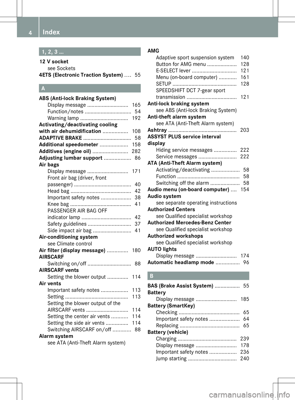
1, 2, 3 ...
12 V socket see Sockets
4ETS (Electronic Traction System) ....55 A
ABS (Anti-lock Braking System) Display message ............................ 165
Function/notes ................................ 54
Warning lamp ................................. 192
Activating/deactivating cooling
with air dehumidification .................108
ADAPTIVE BRAKE ................................. 58
Additional speedometer ...................158
Additives (engine oil) ........................282
Adjusting lumbar support ..................86
Air bags Display message ............................ 171
Front air bag (driver, front
passenger) ....................................... 40
Head bag ......................................... 42
Important safety notes ....................38
Knee bag .......................................... 41
PASSENGER AIR BAG OFF
indicator lamp .................................. 42
Safety guidelines ............................. 37
Side impact air bag ..........................41
Air-conditioning system
see Climate control
Air filter (display message) ..............180
AIRSCARF Switching on/off .............................. 88
AIRSCARF vents
Setting the blower output ..............114
Air vents
Important safety notes ..................113
Setting ........................................... 113
Setting the blower output of the
AIRSCARF vents ............................ .114
Setting the center air vents ...........114
Setting the side air vents ...............114
Switching AIRSCARF on/off ............88
Alarm system
see ATA (Anti-Theft Alarm system) AMG
Adaptive sport suspension system 140
Button for AMG menu ....................128
E-SELECT leve r.............................. 121
Menu (on-board computer) ............161
SETUP ............................................ 128
SPEEDSHIFT DCT 7-gear sport
transmission .................................. 121
Anti-lock braking system
see ABS (Anti-lock Braking System)
Anti-theft alarm system
see ATA (Anti-Theft Alarm system)
Ashtray ............................................... 203
ASSYST PLUS service interval
display
Hiding service messages ...............222
Service messages ..........................222
ATA (Anti-Theft Alarm system)
Activating/deactivating ...................58
Function .......................................... .58
Switching off the alarm ....................58
Audio menu (on-board computer) ....154
Audio system see separate operating instructions
Authorized Centers
see Qualified specialist workshop
Authorized Mercedes-Benz Center
see Qualified specialist workshop
Authorized workshops
see Qualified specialist workshop
AUTO lights
Display message ............................ 174
Automatic headlamp mode ................96 B
BAS (Brake Assist System) .................55
Battery Display message ............................ 185
Battery (SmartKey)
Checking .......................................... 65
Important safety notes ....................64
Replacing ......................................... 65
Battery (vehicle)
Charging ........................................ 239
Display message ............................ 178
Important safety notes ..................236
Jump starting ................................. 2404
Index
Page 8 of 292
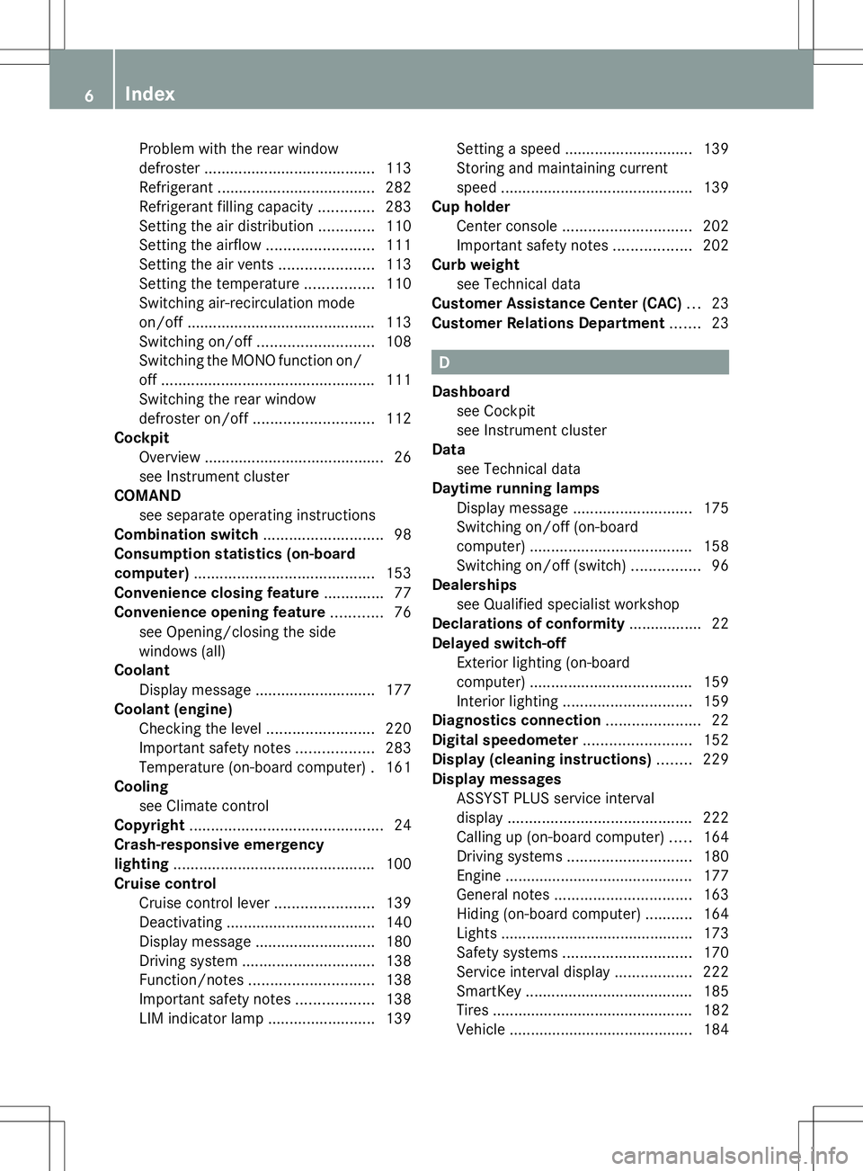
Problem with the rear window
defroster
........................................ 113
Refrigerant ..................................... 282
Refrigerant filling capacity .............283
Setting the air distribution .............110
Setting the airflow .........................111
Setting the air vents ......................113
Setting the temperature ................110
Switching air-recirculation mode
on/off ............................................ 113
Switching on/off ........................... 108
Switching the MONO function on/
off .................................................. 111
Switching the rear window
defroster on/off ............................ 112
Cockpit
Overview .......................................... 26
see Instrument cluster
COMAND
see separate operating instructions
Combination switch ............................98
Consumption statistics (on-board
computer) .......................................... 153
Convenience closing feature ..............77
Convenience opening feature ............76
see Opening/closing the side
windows (all)
Coolant
Display message ............................ 177
Coolant (engine)
Checking the level .........................220
Important safety notes ..................283
Temperature (on-board computer) .161
Cooling
see Climate control
Copyright ............................................. 24
Crash-responsive emergency
lighting ............................................... 100
Cruise control Cruise control lever .......................139
Deactivating ................................... 140
Display message ............................ 180
Driving system ............................... 138
Function/notes ............................. 138
Important safety notes ..................138
LIM indicator lamp .........................139Setting a speed
.............................. 139
Storing and maintaining current
speed ............................................ .139
Cup holder
Center console .............................. 202
Important safety notes ..................202
Curb weight
see Technical data
Customer Assistance Center (CAC) ...23
Customer Relations Department .......23 D
Dashboard see Cockpit
see Instrument cluster
Data
see Technical data
Daytime running lamps
Display message ............................ 175
Switching on/off (on-board
computer) ...................................... 158
Switching on/off (switch) ................96
Dealerships
see Qualified specialist workshop
Declarations of conformity ................. 22
Delayed switch-off Exterior lighting (on-board
computer) ...................................... 159
Interior lighting .............................. 159
Diagnostics connection ......................22
Digital speedometer .........................152
Display (cleaning instructions) ........229
Display messages ASSYST PLUS service interval
displa y........................................... 222
Calling up (on-board computer) .....164
Driving systems ............................. 180
Engine ............................................ 177
General notes ................................ 163
Hiding (on-board computer) ...........164
Lights ............................................ .173
Safety systems .............................. 170
Service interval displa y.................. 222
SmartKey ....................................... 185
Tires ............................................... 182
Vehicle .......................................... .184 6
Index
Page 13 of 292
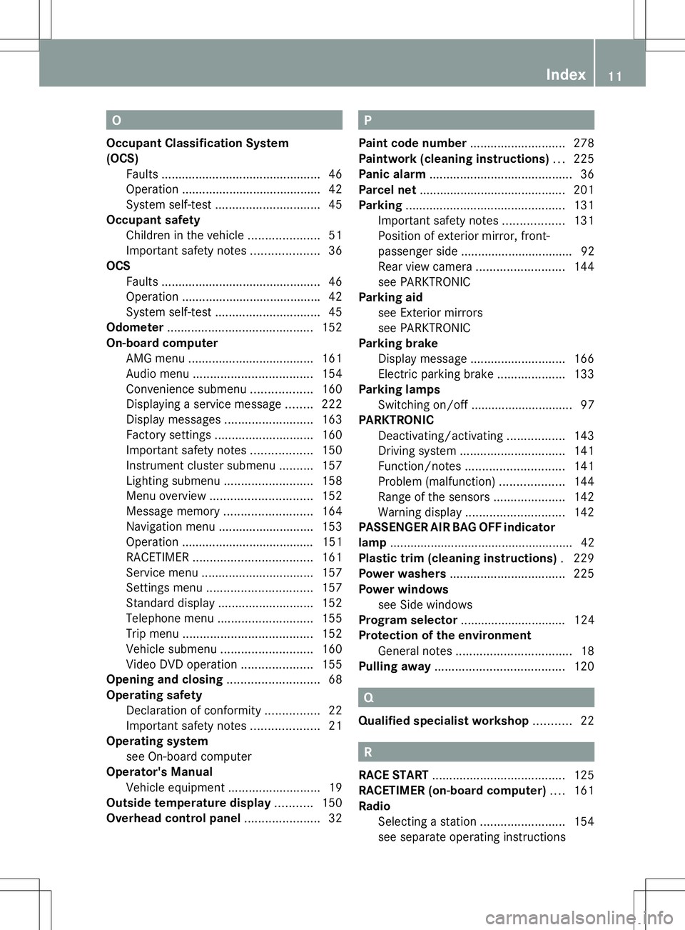
O
Occupant Classification System
(OCS) Faults .............................................. .46
Operation ........................................ .42
System self-test ............................... 45
Occupant safety
Children in the vehicle .....................51
Important safety notes ....................36
OCS
Faults ............................................... 46
Operation ........................................ .42
System self-test ............................... 45
Odometer ........................................... 152
On-board computer AMG menu ..................................... 161
Audio menu ................................... 154
Convenience submenu ..................160
Displaying a service message ........222
Display messages ..........................163
Factory settings ............................. 160
Important safety notes ..................150
Instrument cluster submenu ..........157
Lighting submenu .......................... 158
Menu overview .............................. 152
Message memory .......................... 164
Navigation menu ............................ 153
Operation ....................................... 151
RACETIMER ................................... 161
Service menu ................................. 157
Settings menu ............................... 157
Standard displa y............................ 152
Telephone menu ............................ 155
Trip menu ...................................... 152
Vehicle submenu ........................... 160
Video DVD operation .....................155
Opening and closing ...........................68
Operating safety Declaration of conformity ................22
Important safety notes ....................21
Operating system
see On-board computer
Operator's Manual
Vehicle equipment ...........................19
Outside temperature display ...........150
Overhead control panel ......................32 P
Paint code number ............................278
Paintwork (cleaning instructions) ...225
Panic alarm .......................................... 36
Parcel net ........................................... 201
Parking ............................................... 131
Important safety notes ..................131
Position of exterior mirror, front-
passenger side ................................. 92
Rear view camera .......................... 144
see PARKTRONIC
Parking aid
see Exterior mirrors
see PARKTRONIC
Parking brake
Display message ............................ 166
Electric parking brake ....................133
Parking lamps
Switching on/off .............................. 97
PARKTRONIC
Deactivating/activating .................143
Driving system ............................... 141
Function/notes ............................. 141
Problem (malfunction) ...................144
Range of the sensors .....................142
Warning displa y............................. 142
PASSENGER AIR BAG OFF indicator
lamp ...................................................... 42
Plastic trim (cleaning instructions) .229
Power washers .................................. 225
Power windows see Side windows
Program selector ............................... 124
Protection of the environment General notes .................................. 18
Pulling away ...................................... 120 Q
Qualified specialist workshop ...........22 R
RACE START ....................................... 125
RACETIMER (on-board computer) ....161
Radio Selecting a station .........................154
see separate operating instructions Index
11
Page 17 of 292
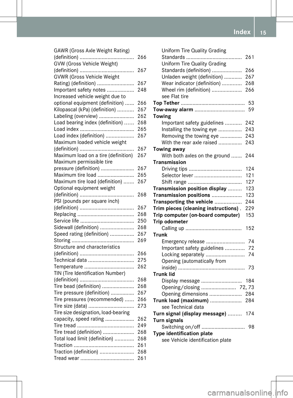
GAWR (Gross Axle Weight Rating)
(definition)
..................................... 266
GVW (Gross Vehicle Weight)
(definition) ..................................... 267
GVWR (Gross Vehicle Weight
Rating) (definition) .........................267
Important safety notes ..................248
Increased vehicle weight due to
optional equipment (definition) ......266
Kilopascal (kPa) (definition) ...........267
Labeling (overview )........................ 262
Load bearing index (definition) ......268
Load index ..................................... 265
Load index (definition) ...................267
Maximum loaded vehicle weight
(definition) ..................................... 267
Maximum load on a tire (definition) 267
Maximum permissible tire
pressure (definition) ....................... 267
Maximum tire loa d......................... 265
Maximum tire load (definition) .......267
Optional equipment weight
(definition) ..................................... 268
PSI (pounds per square inch)
(definition) ..................................... 267
Replacing ....................................... 268
Service life ..................................... 250
Sidewall (definition) .......................268
Speed rating (definition) ................267
Storing ........................................... 269
Structure and characteristics
(definition) ..................................... 266
Technical data ............................... 275
Temperature .................................. 262
TIN (Tire Identification Number)
(definition) ..................................... 268
Tire bead (definition) ......................268
Tire pressure (definition) ................267
Tire pressures (recommended )...... 266
Tire size (data) ............................... 273
Tire size designation, load-bearing
capacity, speed rating .................... 262
Tire tread ....................................... 249
Tire tread (definition) .....................268
Total load limit (definition) .............268
Traction ......................................... 261
Traction (definition) .......................268
Tread wea r..................................... 261Uniform Tire Quality Grading
Standards
...................................... 261
Uniform Tire Quality Grading
Standards (definition) ....................266
Unladen weight (definition) ............267
Wear indicator (definition) .............268
Wheel rim (definition) ....................266
see Flat tire
Top Tether ............................................ 53
Tow-away alarm .................................. 59
Towing Important safety guidelines ...........242
Installing the towing eye ................243
Removing the towing eye ...............243
With the rear axle raised ................243
Towing away
With both axles on the ground .......244
Transmission
Driving tips .................................... 124
Selector lever ................................ 121
Shift range ..................................... 127
Transmission position display .........123
Transmission positions ....................123
Transporting the vehicle ..................244
Trim pieces (cleaning instructions) .229
Trip computer (on-board computer) 153
Trip odometer Calling up ....................................... 152
Trunk
Emergency release ..........................74
Important safety guidelines .............72
Locking separately ...........................74
Opening (automatically from
inside) .............................................. 73
Trunk lid
Display message ............................ 184
Opening/closing ........................72, 73
Opening dimensions ......................284
Trunk load (maximum) ......................284
see Technical data
Turn signal (display message) .........174
Turn signals Switching on/off .............................. 98
Type identification plate
see Vehicle identification plate Index
15
Page 61 of 292
or
X
Insert the SmartKey into the ignition lock.
The alarm is switched off.
i If the alarm stays on for more than
30 seconds, the mbrace emergency call
system (USA only) or Tele Aid system
(Canada only) initiates a call to the
Customer Assistance Center
automatically. The mbrace emergency call
system initiates the call if:
R you have subscribed to the Tele Aid
service.
R the Tele Aid service has been activated
properly.
R the required mobile phone, power supply
and GPS are available. Tow-away alarm
Function An audible and visual alarm is triggered if your
vehicle's angle of inclination is altered while
the tow-away alarm is armed. This can occur
if the vehicle is jacked up on one side, for
example.
Arming X
Make sure that:
R
the doors are closed.
R the trunk lid is closed.
Only then is the tow-away alarm armed.
X Lock the vehicle with the SmartKey.
The tow-away alarm is armed after
approximately 30 seconds.
Deactivating X
Unlock the vehicle with the SmartKey.
The tow-away alarm is deactivated
automatically. Disarming
X
Select key position 0with the Start/Stop
button.
or
X Remove the SmartKey from the ignition
lock.
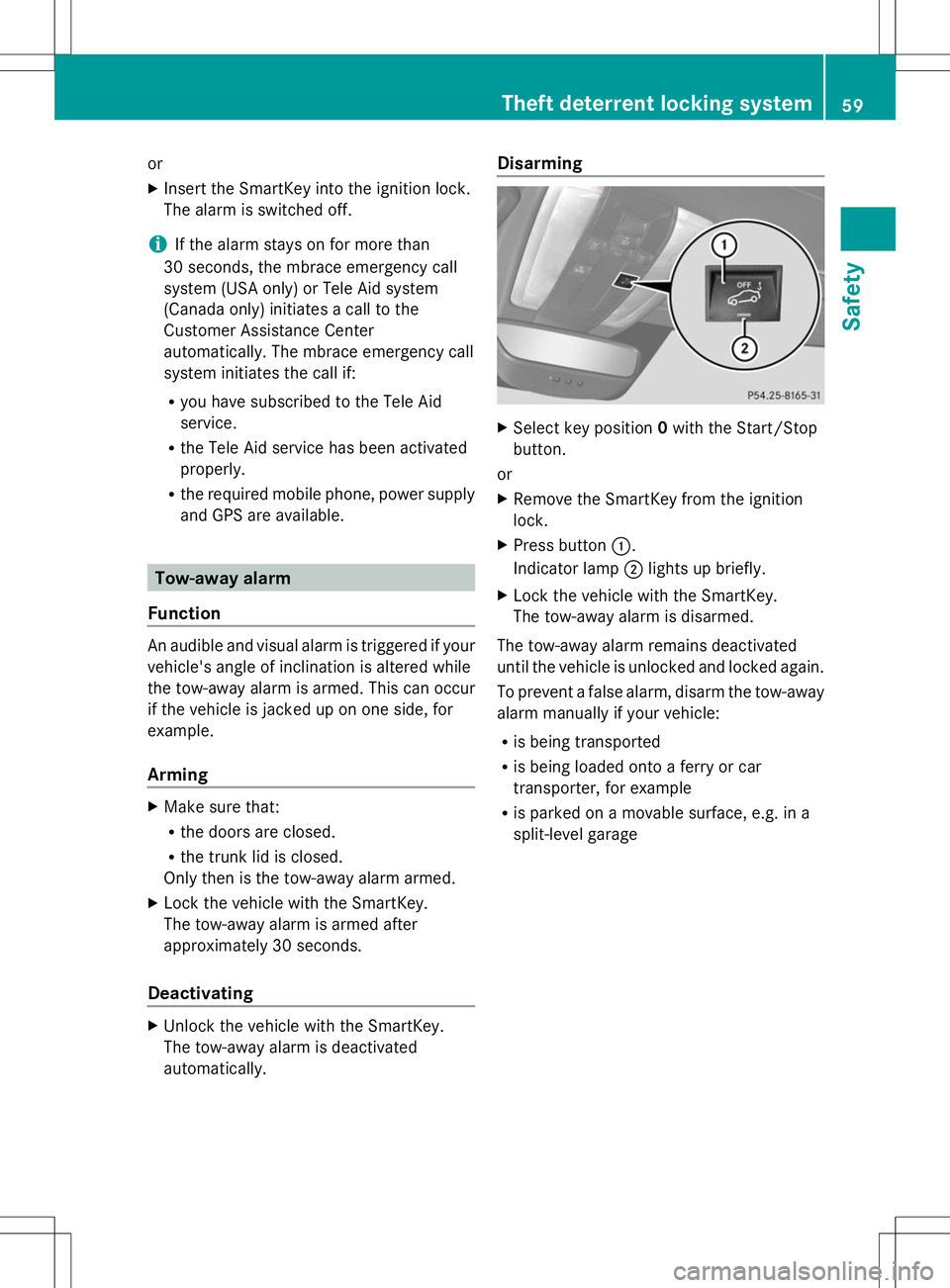
X Press button :.
Indicator lamp ;lights up briefly.
X Lock the vehicle with the SmartKey.
The tow-away alarm is disarmed.
The tow-away alarm remains deactivated
until the vehicle is unlocked and locked again.
To prevent a false alarm, disarm the tow-away
alarm manually if your vehicle:
R is being transported
R is being loaded onto a ferry or car
transporter, for example
R is parked on a movable surface, e.g. in a
split-level garage Theft deterrent locking system
59Safety Z
Page 136 of 292
X
While driving, push handle :of the electric
parking brake (Y page 133).
i The vehicle is braked as long as you keep
the handle of the electric parking brake
pressed. The longer the electric parking
brake handle is depressed, the greater the
braking force.
During braking:
R a warning tone sounds
R the Release Parking Brake
Release Parking Brake message
appears
R the red F(USA only) or !(Canada
only) indicator lamp in the instrument
cluster appears.
When the vehicle has been braked to a
standstill, the electric parking brake is
engaged. Parking the vehicle for a long period
If you leave the vehicle parked for longer than
four weeks, the battery may be damaged by
exhaustive discharging.
If you leave the vehicle parked up for longer
than six weeks, the vehicle may suffer
damage as a result of lack of use.
X Visit a qualified specialist workshop and
seek advice.
i You can obtain information about trickle
chargers from a qualified specialist
workshop. Driving tips
General driving tips
Important safety notes G
WARNING
If you switch off the ignition while driving,
safety-relevant functions are only available
with limitations, or not at all. This could affect,
for example, the power steering and the brake
boosting effect. You will require considerably more effort to steer and brake. There is a risk
of an accident.
Do not switch off the ignition while driving.
G
WARNING
If you operate mobile communication
equipment while driving, you will be
distracted from traffic conditions. You could
also lose control of the vehicle. There is a risk
of an accident.
Only operate this equipment when the vehicle
is stationary.
Observe the legal requirements for the
country in which you are driving. Some
jurisdictions prohibit the driver from using a
mobile phone while driving a vehicle.
If you make a call while driving, always use
hands-free mode. Only operate the telephone
when the traffic situation permits. If you are
unsure, pull over to a safe location and stop
before operating the telephone.
Bear in mind that at a speed of only 30 mph
(approximately 50 km/h), the vehicle covers
a distance of 44 ft (approximately 14 m) per
second.
Drive sensibly – save fuel Observe the following tips to save fuel:
X
The tires should always be inflated to the
recommended tire pressure.
X Remove unnecessary loads.
X Warm up the engine at low engine speeds.
X Avoid frequent acceleration or braking.
X Have all maintenance work carried out
according to the service intervals listed in
the Maintenance Booklet or the service
interval display.
Fuel consumption also increases when
driving in cold weather, in stop-start traffic
and in hilly terrain. 134
Driving tipsDriving and parking
Page 207 of 292
The mbrace system
To adjust the volume during an mbrace call,
proceed as follows:
X Press the WorX button on the
multifunction steering wheel.
or
X Use the volume controller of COMAND.
The mbrace system provides various
services, e.g.:
R Automatic and manual emergency call
R Roadside Assistance call
R MB Info call
USA only: you can find information and a
description of all available features under
"Owners Online" at http://www.mbusa.com.
Self-diagnosis of the system After you have switched on the ignition, the
system carries out a self-diagnosis.
A malfunction in the system has been
detected if one of the following conditions
occurs:
R The indicator lamp in the SOS button does
not come on during the system self-test.
R The indicator lamp in the FRoadside
Assistance button does not light up during
self-diagnosis of the system.
R The indicator lamp in the ïMB Info call
button does not light up during self-
diagnosis of the system.
R The indicator lamp in one or more of the
following buttons continues to light up red
after the system self-diagnosis:
- SOS button
- F Roadside Assistance call button
- ï MB Info call button
R the Tele
Tele Aid AidInoperative
Inoperative orTele
Tele Aid
Aid
Not Activated Not Activated message appears in the
multifunction display after the system self-
diagnosis.
If a malfunction is indicated as outlined
above, the system may not operate as expected. In the event of an emergency, help
will have to be summoned by other means.
Have the system checked at the nearest
authorized Mercedes-Benz Center or contact
the following service hotlines:
R
USA: Mercedes-Benz Customer Assistance
Center at
1-800-FOR-MERCedes (1-800-367-6372)
or 1-866-990-9007
R Canada: Customer Service at
1-888-923-8367
Emergency call Important safety notes
!
You must have a license agreement to
activate the mbrace service. Ensure that
your system is activated and ready for use,
and press the ïMB Info call button to
register. If one of these steps is not carried
out, it may not be possible to activate the
system.
If you have questions about the activation,
contact one of the following telephone
hotlines:
R USA: Mercedes-Benz Customer
Assistance center at
1-800-FOR-MERCedes
(1-800-367-6372) or 1-866-990-9007
R Canada: Customer Service at
1-888-923-8367
General notes
An emergency call is dialed automatically if
an air bag or Emergency Tensioning Device is
triggered.
i You cannot end an automatically
triggered emergency call yourself.
An emergency call can also be initiated
manually.
As soon as the emergency call has been
initiated, the indicator lamp in the SOS button
flashes. The Connecting Call Connecting Call message
appears in the multifunction display.
The audio output is muted. Features
205Stowage an d features Z
Page 209 of 292
vehicle immediately after pressing the SOS
button, you will not know whether mbrace
placed the emergency call. In this case,
always summon assistance by other
means.
Roadside Assistance button X
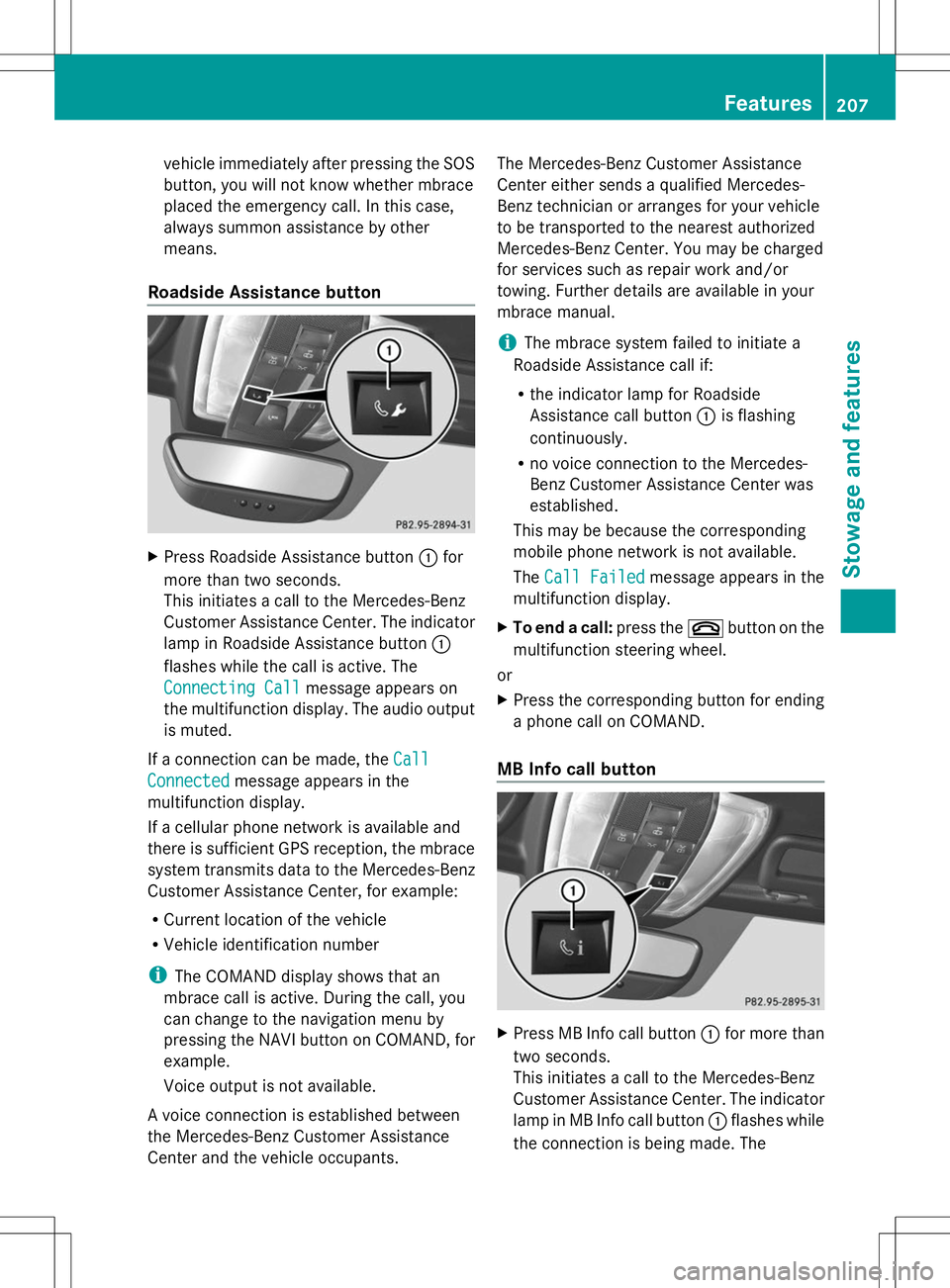
Press Roadside Assistance button :for
more than two seconds.
This initiates a call to the Mercedes-Benz
Customer Assistance Center. The indicator
lamp in Roadside Assistance button :
flashes while the call is active. The
Connecting Call
Connecting Call message appears on
the multifunction display. The audio output
is muted.
If a connection can be made, the Call
Call
Connected Connected message appears in the
multifunction display.
If a cellular phone network is available and
there is sufficient GPS reception, the mbrace
system transmits data to the Mercedes-Benz
Customer Assistance Center, for example:
R Current location of the vehicle
R Vehicle identification number
i The COMAND display shows that an
mbrace call is active. During the call, you
can change to the navigation menu by
pressing the NAVI button on COMAND, for
example.
Voice output is not available.
A voice connection is established between
the Mercedes-Benz Customer Assistance
Center and the vehicle occupants. The Mercedes-Benz Customer Assistance
Center either sends a qualified Mercedes-
Benz technician or arranges for your vehicle
to be transported to the nearest authorized
Mercedes-Benz Center. You may be charged
for services such as repair work and/or
towing. Further details are available in your
mbrace manual.
i
The mbrace system failed to initiate a
Roadside Assistance call if:
R the indicator lamp for Roadside
Assistance call button :is flashing
continuously.
R no voice connection to the Mercedes-
Benz Customer Assistance Center was
established.
This may be because the corresponding
mobile phone network is not available.
The Call Failed Call Failed message appears in the
multifunction display.
X To end a call: press the~button on the
multifunction steering wheel.
or
X Press the corresponding button for ending
a phone call on COMAND.
MB Info call button X
Press MB Info call button :for more than
two seconds.
This initiates a call to the Mercedes-Benz
Customer Assistance Center. The indicator
lamp in MB Info call button :flashes while
the connection is being made. The Features
207Stowage and features Z
Page 210 of 292
Connecting
Connecting
Call
Callmessage appears in the
multifunction display and the COMAND
system is muted.
If a connection can be made, the Call
Call
Connected Connected message appears in the
multifunction display.
If a cellular phone network is available and
there is sufficient GPS reception, the mbrace
system transmits data to the Mercedes-Benz
Customer Assistance Center, for example:
R Current location of the vehicle
R Vehicle identification number
i The COMAND display shows that an
mbrace call is active. During the call, you
can change to the navigation menu by
pressing the NAVI button on COMAND, for
example.
Voice output is not available.
A voice connection is established between
the Mercedes-Benz Customer Assistance
Center and the vehicle occupants. You can
obtain information on how to operate your
vehicle's systems, on the location of the
nearest authorized Mercedes-Benz Center,
and on further products and services offered
by Mercedes-Benz USA.
USA only: you can find further information on
the mbrace system under "Owners Online" at
http://www.mbusa.com.
i The mbrace system failed to initiate an
MB Info call if:
R the indicator lamp in MB Info call
button :is flashing continuously.
R no voice connection to the Mercedes-
Benz Customer Assistance Center was
established.
This may be because the corresponding
mobile phone network is not available.
The Call Failed
Call Failed message appears in the
multifunction display. X
To end a call: press the~button on the
multifunction steering wheel.
or
X Press the corresponding button for ending
a phone call on COMAND.
Call priority When service calls are active, e.g. Roadside
Assistance or MB Info calls, an emergency
call can still be initiated. In this case, an
emergency call will take priority and override
all other active calls.
The indicator lamp of the respective button
flashes until the call is ended. An emergency
call can only be terminated by the Mercedes-
Benz Customer Assistance Center.
All other calls can be ended by pressing:
R
the ~ button on the multifunction
steering wheel
R or the corresponding COMAND button for
ending a telephone call
i If an mbrace call is initiated, audio output
is muted. The mobile phone is no longer
connected to COMAND. If you must use
your mobile phone, we recommend that
you do this only when the vehicle is
stationary and in a safe location.
Downloading destinations in COMAND Downloading destinations
i
Information on the components and
operating principles of COMAND can be
found in the separate COMAND operating
instructions.
This service is part of the mbrace PLUS
Package and cannot be purchased
separately.
i You can only use the Destination
Download function if the vehicle is
equipped with a navigation system.
Destination Download gives you access to a
data bank with over 15 million Points of
Interest (POIs). These can be downloaded on 208
FeaturesStowage and features
Page 214 of 292
Alternatively, you can call the following
telephone assistance services:
R USA: Mercedes-Benz Customer
Assistance Center at
1-800-FOR-MERCedes
R Canada: Customer Service at
1-800-387-0100
i Notes about the declaration of conformity
can be found here (Y page 22).
USA: FCC ID: CB2HMIHL4
Canada: IC: 279B-HMIHL4
Programming Programing buttons
Pay attention to the "Important safety notes"
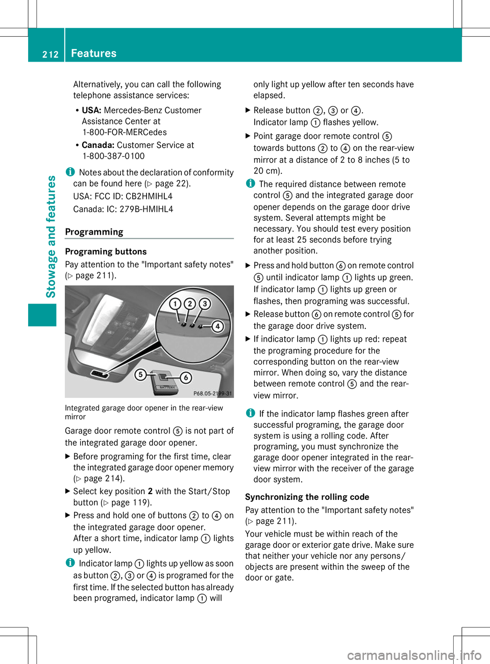
(Y page 211). Integrated garage door opener in the rear-view
mirror
Garage door remote control Ais not part of
the integrated garage door opener.
X Before programing for the first time, clear
the integrated garage door opener memory
(Y page 214).
X Select key position 2with the Start/Stop
button ( Ypage 119).
X Press and hold one of buttons ;to? on
the integrated garage door opener.
After a short time, indicator lamp :lights
up yellow.
i Indicator lamp :lights up yellow as soon
as button ;,=or? is programed for the
first time. If the selected button has already
been programed, indicator lamp :will only light up yellow after ten seconds have
elapsed.
X Release button ;,=or?.
Indicator lamp :flashes yellow.
X Point garage door remote control A
towards buttons ;to? on the rear-view
mirror at a distance of 2 to 8 inches (5 to
20 cm).
i The required distance between remote
control Aand the integrated garage door
opener depends on the garage door drive
system. Several attempts might be
necessary. You should test every position
for at least 25 seconds before trying
another position.
X Press and hold button Bon remote control
A until indicator lamp :lights up green.
If indicator lamp :lights up green or
flashes, then programing was successful.
X Release button Bon remote control Afor
the garage door drive system.
X If indicator lamp :lights up red: repeat
the programing procedure for the
corresponding button on the rear-view
mirror. When doing so, vary the distance
between remote control Aand the rear-
view mirror.
i If the indicator lamp flashes green after
successful programing, the garage door
system is using a rolling code. After
programing, you must synchronize the
garage door opener integrated in the rear-
view mirror with the receiver of the garage
door system.
Synchronizing the rolling code
Pay attention to the "Important safety notes"
(Y page 211).
Your vehicle must be within reach of the
garage door or exterior gate drive. Make sure
that neither your vehicle nor any persons/
objects are present within the sweep of the
door or gate. 212
FeaturesSto
wage an d features