check engine MERCEDES-BENZ SPRINTER 2006 Service Manual
[x] Cancel search | Manufacturer: MERCEDES-BENZ, Model Year: 2006, Model line: SPRINTER, Model: MERCEDES-BENZ SPRINTER 2006Pages: 2305, PDF Size: 48.12 MB
Page 1789 of 2305
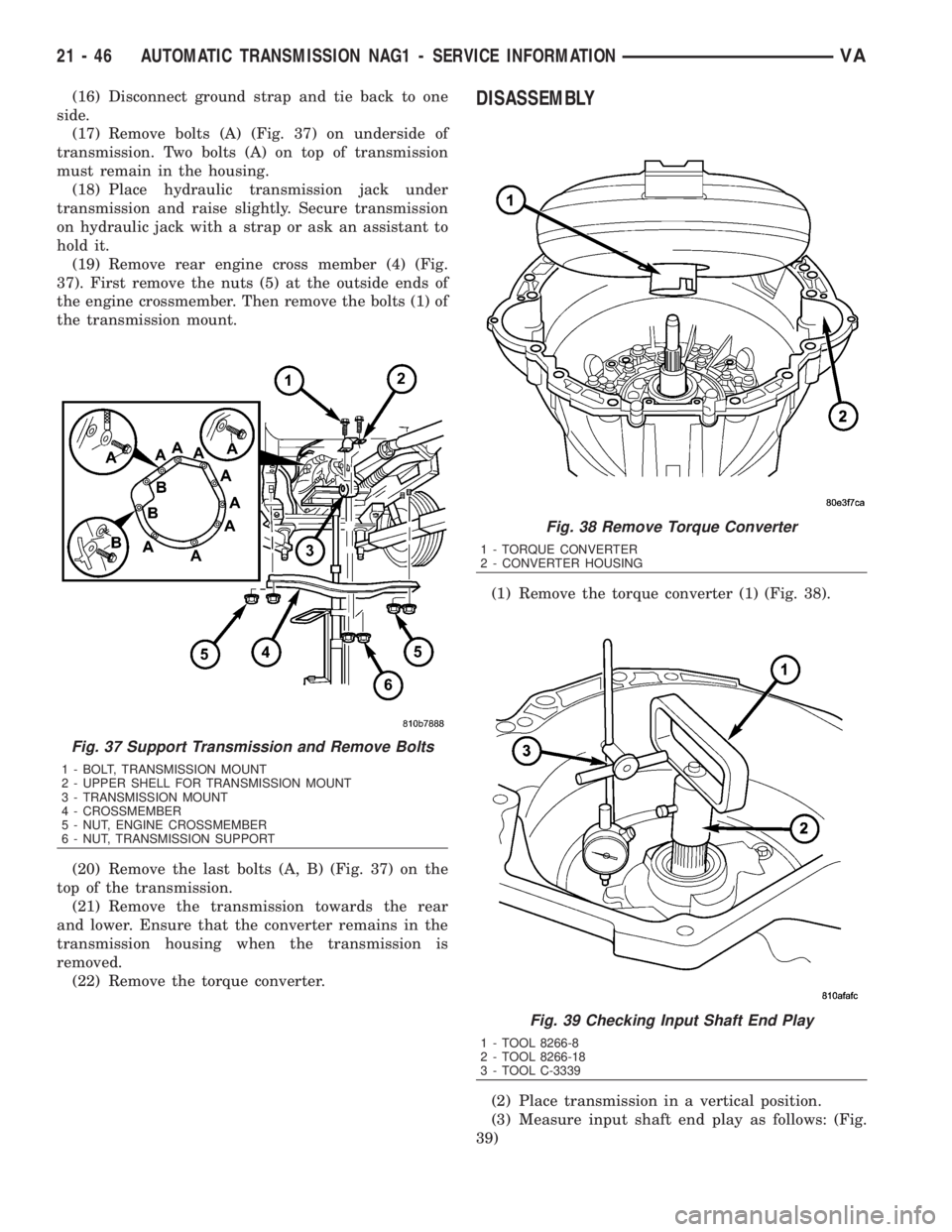
(16) Disconnect ground strap and tie back to one
side.
(17) Remove bolts (A) (Fig. 37) on underside of
transmission. Two bolts (A) on top of transmission
must remain in the housing.
(18) Place hydraulic transmission jack under
transmission and raise slightly. Secure transmission
on hydraulic jack with a strap or ask an assistant to
hold it.
(19) Remove rear engine cross member (4) (Fig.
37). First remove the nuts (5) at the outside ends of
the engine crossmember. Then remove the bolts (1) of
the transmission mount.
(20) Remove the last bolts (A, B) (Fig. 37) on the
top of the transmission.
(21) Remove the transmission towards the rear
and lower. Ensure that the converter remains in the
transmission housing when the transmission is
removed.
(22) Remove the torque converter.DISASSEMBLY
(1) Remove the torque converter (1) (Fig. 38).
(2) Place transmission in a vertical position.
(3) Measure input shaft end play as follows: (Fig.
39)
Fig. 37 Support Transmission and Remove Bolts
1 - BOLT, TRANSMISSION MOUNT
2 - UPPER SHELL FOR TRANSMISSION MOUNT
3 - TRANSMISSION MOUNT
4 - CROSSMEMBER
5 - NUT, ENGINE CROSSMEMBER
6 - NUT, TRANSMISSION SUPPORT
Fig. 38 Remove Torque Converter
1 - TORQUE CONVERTER
2 - CONVERTER HOUSING
Fig. 39 Checking Input Shaft End Play
1 - TOOL 8266-8
2 - TOOL 8266-18
3 - TOOL C-3339
21 - 46 AUTOMATIC TRANSMISSION NAG1 - SERVICE INFORMATIONVA
Page 1875 of 2305
CAUSES OF BURNT FLUID
Burnt, discolored fluid is a result of overheating
which has three primary causes.
1. Internal clutch slippage, usually caused by low
line pressure, inadequate clutch apply pressure, or
clutch seal failure.
2. A result of restricted fluid flow through the
main and/or auxiliary cooler. This condition is usu-
ally the result of a faulty or improperly installed
drainback valve, a damaged oil cooler, or severe
restrictions in the coolers and lines caused by debris
or kinked lines.
3. Heavy duty operation with a vehicle not prop-
erly equipped for this type of operation. Trailer tow-
ing or similar high load operation will overheat the
transmission fluid if the vehicle is improperly
equipped. Such vehicles should have an auxiliary
transmission fluid cooler, a heavy duty cooling sys-
tem, and the engine/axle ratio combination needed to
handle heavy loads.
FLUID CONTAMINATION
Transmission fluid contamination is generally a
result of:
²adding incorrect fluid
²failure to clean dipstick and fill tube when
checking level
²engine coolant entering the fluid
²internal failure that generates debris
²overheat that generates sludge (fluid break-
down)
²failure to replace contaminated converter after
repair
The use of non-recommended fluids can result in
transmission failure. The usual results are erratic
shifts, slippage, abnormal wear and eventual failure
due to fluid breakdown and sludge formation. Avoid
this condition by using recommended fluids only.
The dipstick cap and fill tube should be wiped
clean before checking fluid level. Dirt, grease and
other foreign material on the cap and tube could fall
into the tube if not removed beforehand. Take the
time to wipe the cap and tube clean before withdraw-
ing the dipstick.
Engine coolant in the transmission fluid is gener-
ally caused by a cooler malfunction. The only remedy
is to replace the radiator as the cooler in the radiator
is not a serviceable part. If coolant has circulated
through the transmission, an overhaul is necessary.
The torque converter should be replaced whenever
a failure generates sludge and debris. This is neces-
sary because normal converter flushing procedures
will not remove all contaminants.
STANDARD PROCEDURE
CHECK OIL LEVEL
(1) Verify that the vehicle is parked on a level sur-
face.
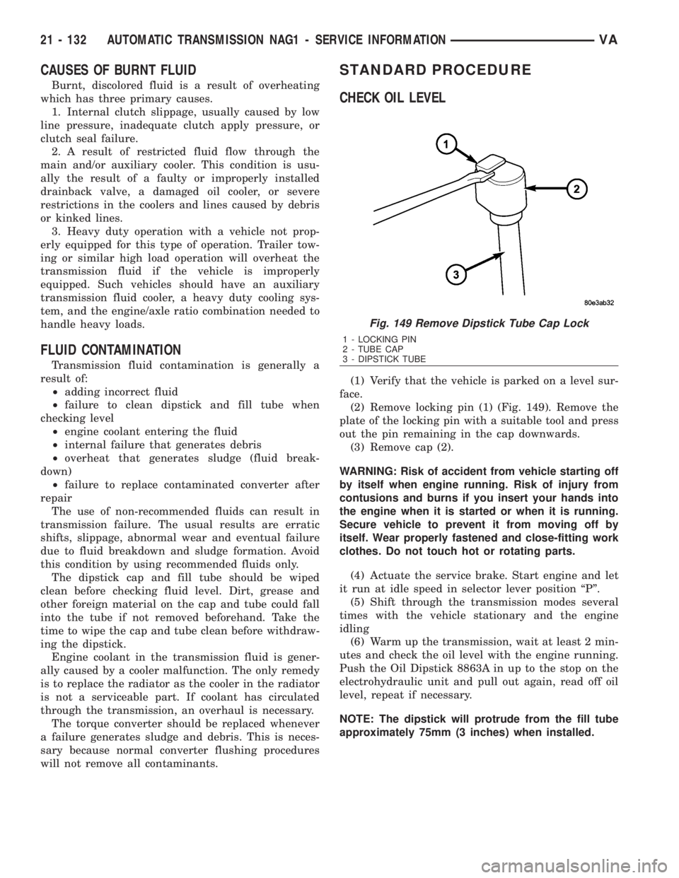
(2) Remove locking pin (1) (Fig. 149). Remove the
plate of the locking pin with a suitable tool and press
out the pin remaining in the cap downwards.
(3) Remove cap (2).
WARNING: Risk of accident from vehicle starting off
by itself when engine running. Risk of injury from
contusions and burns if you insert your hands into
the engine when it is started or when it is running.
Secure vehicle to prevent it from moving off by
itself. Wear properly fastened and close-fitting work
clothes. Do not touch hot or rotating parts.
(4) Actuate the service brake. Start engine and let
it run at idle speed in selector lever position ªPº.
(5) Shift through the transmission modes several
times with the vehicle stationary and the engine
idling
(6) Warm up the transmission, wait at least 2 min-
utes and check the oil level with the engine running.
Push the Oil Dipstick 8863A in up to the stop on the
electrohydraulic unit and pull out again, read off oil
level, repeat if necessary.
NOTE: The dipstick will protrude from the fill tube
approximately 75mm (3 inches) when installed.
Fig. 149 Remove Dipstick Tube Cap Lock
1 - LOCKING PIN
2 - TUBE CAP
3 - DIPSTICK TUBE
21 - 132 AUTOMATIC TRANSMISSION NAG1 - SERVICE INFORMATIONVA
Page 1877 of 2305
To avoid overfilling transmission after a fluid
change or overhaul, perform the following procedure:
(1) Verify that the vehicle is parked on a level sur-
face.
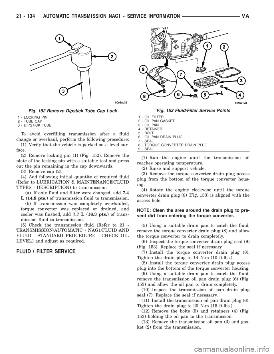
(2) Remove locking pin (1) (Fig. 152). Remove the
plate of the locking pin with a suitable tool and press
out the pin remaining in the cap downwards.
(3) Remove cap (2).
(4) Add following initial quantity of required fluid
(Refer to LUBRICATION & MAINTENANCE/FLUID
TYPES - DESCRIPTION) to transmission:
(a) If only fluid and filter were changed, add7.4
L (14.8 pts.)of transmission fluid to transmission.
(b) If transmission was completely overhauled,
torque converter was replaced or drained, and
cooler was flushed, add7.7 L (16.3 pts.)of trans-
mission fluid to transmission.
(5) Check the transmission fluid (Refer to 21 -
TRANSMISSION/AUTOMATIC - NAG1/FLUID AND
FLUID - STANDARD PROCEDURE - CHECK OIL
LEVEL) and adjust as required.
FLUID / FILTER SERVICE
(1) Run the engine until the transmission oil
reaches operating temperature.
(2) Raise and support vehicle.
(3) Remove the torque converter drain plug access
plug from the bottom of the torque converter hous-
ing.
(4) Rotate the engine clockwise until the torque
converter drain plug (8) (Fig. 153) is aligned with the
access hole.
NOTE: Clean the area around the drain plug to pre-
vent dirt from entering the torque converter.
(5) Using a suitable drain pan to catch the fluid,
remove the torque converter drain plug (8) and allow
the torque converter to drain completely.
(6) Inspect the torque converter drain plug seal (9)
(Fig. 153). Replace the seal if necessary.
(7) Install the torque converter drain plug (8).
Tighten the drain plug to 14 N´m (10 ft.lbs.).
(8) Install the torque converter drain plug access
plug into the bottom of the torque converter housing.
(9) Using a suitable drain pan to catch the fluid,
remove the transmission oil pan drain plug (6) (Fig.
153) and allow the oil pan to drain completely.
(10) Inspect the transmission oil pan drain plug
seal (7). Replace the seal if necessary.
(11) Install the transmission oil pan drain plug (6).
Tighten the drain plug to 20 N´m (15 ft.lbs.).
(12) Remove the bolts (5) and retainers (4) (Fig.
153) holding the oil pan to the transmission.
(13) Remove the transmission oil pan (3) and gas-
ket (2) from the transmission.
Fig. 152 Remove Dipstick Tube Cap Lock
1 - LOCKING PIN
2 - TUBE CAP
3 - DIPSTICK TUBE
Fig. 153 Fluid/Filter Service Points
1 - OIL FILTER
2 - OIL PAN GASKET
3 - OIL PAN
4 - RETAINER
5 - BOLT
6 - OIL PAN DRAIN PLUG
7 - SEAL
8 - TORQUE CONVERTER DRAIN PLUG
9 - SEAL
21 - 134 AUTOMATIC TRANSMISSION NAG1 - SERVICE INFORMATIONVA
Page 1881 of 2305
ASSEMBLY
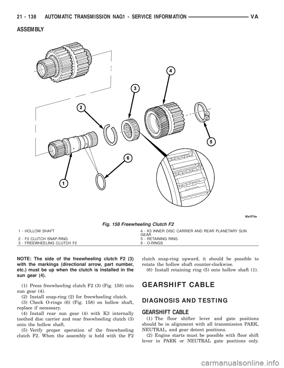
NOTE: The side of the freewheeling clutch F2 (3)
with the markings (directional arrow, part number,
etc.) must be up when the clutch is installed in the
sun gear (4).
(1) Press freewheeling clutch F2 (3) (Fig. 158) into
sun gear (4).
(2) Install snap-ring (2) for freewheeling clutch.
(3) Check O-rings (6) (Fig. 158) on hollow shaft,
replace if necessary.
(4) Install rear sun gear (4) with K3 internally
toothed disc carrier and rear freewheeling clutch (3)
onto the hollow shaft.
(5) Verify proper operation of the freewheeling
clutch F2. When the assembly is held with the F2clutch snap-ring upward, it should be possible to
rotate the hollow shaft counter-clockwise.
(6) Install retaining ring (5) onto hollow shaft (1).
GEARSHIFT CABLE
DIAGNOSIS AND TESTING
GEARSHIFT CABLE
(1) The floor shifter lever and gate positions
should be in alignment with all transmission PARK,
NEUTRAL, and gear detent positions.
(2) Engine starts must be possible with floor shift
lever in PARK or NEUTRAL gate positions only.
Fig. 158 Freewheeling Clutch F2
1 - HOLLOW SHAFT 4 - K3 INNER DISC CARRIER AND REAR PLANETARY SUN
GEAR
2 - F2 CLUTCH SNAP-RING 5 - RETAINING RING
3 - FREEWHEELING CLUTCH F2 6 - O-RINGS
21 - 138 AUTOMATIC TRANSMISSION NAG1 - SERVICE INFORMATIONVA
Page 1911 of 2305
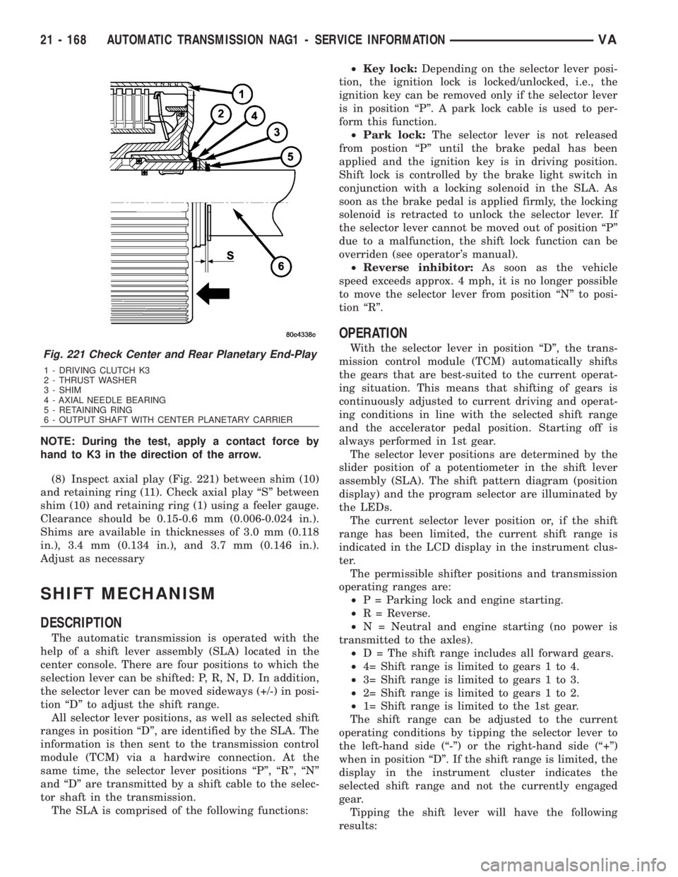
NOTE: During the test, apply a contact force by
hand to K3 in the direction of the arrow.
(8) Inspect axial play (Fig. 221) between shim (10)
and retaining ring (11). Check axial play ªSº between
shim (10) and retaining ring (1) using a feeler gauge.
Clearance should be 0.15-0.6 mm (0.006-0.024 in.).
Shims are available in thicknesses of 3.0 mm (0.118
in.), 3.4 mm (0.134 in.), and 3.7 mm (0.146 in.).
Adjust as necessary
SHIFT MECHANISM
DESCRIPTION
The automatic transmission is operated with the
help of a shift lever assembly (SLA) located in the
center console. There are four positions to which the
selection lever can be shifted: P, R, N, D. In addition,
the selector lever can be moved sideways (+/-) in posi-
tion ªDº to adjust the shift range.
All selector lever positions, as well as selected shift
ranges in position ªDº, are identified by the SLA. The
information is then sent to the transmission control
module (TCM) via a hardwire connection. At the
same time, the selector lever positions ªPº, ªRº, ªNº
and ªDº are transmitted by a shift cable to the selec-
tor shaft in the transmission.
The SLA is comprised of the following functions:²Key lock:Depending on the selector lever posi-
tion, the ignition lock is locked/unlocked, i.e., the
ignition key can be removed only if the selector lever
is in position ªPº. A park lock cable is used to per-
form this function.
²Park lock:The selector lever is not released
from postion ªPº until the brake pedal has been
applied and the ignition key is in driving position.
Shift lock is controlled by the brake light switch in
conjunction with a locking solenoid in the SLA. As
soon as the brake pedal is applied firmly, the locking
solenoid is retracted to unlock the selector lever. If
the selector lever cannot be moved out of position ªPº
due to a malfunction, the shift lock function can be
overriden (see operator's manual).
²Reverse inhibitor:As soon as the vehicle
speed exceeds approx. 4 mph, it is no longer possible
to move the selector lever from position ªNº to posi-
tion ªRº.
OPERATION
With the selector lever in position ªDº, the trans-
mission control module (TCM) automatically shifts
the gears that are best-suited to the current operat-
ing situation. This means that shifting of gears is
continuously adjusted to current driving and operat-
ing conditions in line with the selected shift range
and the accelerator pedal position. Starting off is
always performed in 1st gear.
The selector lever positions are determined by the
slider position of a potentiometer in the shift lever
assembly (SLA). The shift pattern diagram (position
display) and the program selector are illuminated by
the LEDs.
The current selector lever position or, if the shift
range has been limited, the current shift range is
indicated in the LCD display in the instrument clus-
ter.
The permissible shifter positions and transmission
operating ranges are:
²P = Parking lock and engine starting.
²R = Reverse.
²N = Neutral and engine starting (no power is
transmitted to the axles).
²D = The shift range includes all forward gears.
²4= Shift range is limited to gears 1 to 4.
²3= Shift range is limited to gears 1 to 3.
²2= Shift range is limited to gears 1 to 2.
²1= Shift range is limited to the 1st gear.
The shift range can be adjusted to the current
operating conditions by tipping the selector lever to
the left-hand side (ª-º) or the right-hand side (ª+º)
when in position ªDº. If the shift range is limited, the
display in the instrument cluster indicates the
selected shift range and not the currently engaged
gear.
Tipping the shift lever will have the following
results:Fig. 221 Check Center and Rear Planetary End-Play
1 - DRIVING CLUTCH K3
2 - THRUST WASHER
3 - SHIM
4 - AXIAL NEEDLE BEARING
5 - RETAINING RING
6 - OUTPUT SHAFT WITH CENTER PLANETARY CARRIER
21 - 168 AUTOMATIC TRANSMISSION NAG1 - SERVICE INFORMATIONVA
Page 1936 of 2305
²Vehicle drift
For proper tire pressure specification refer to the
Tire Inflation Pressure Chart provided with the vehi-
cles Owners Manual. A Certification Label on the
drivers side door pillar provides the minimum tire
and rim size for the vehicle. The label also list the
cold inflation pressure for these tires at full load
operation
Tire pressures have been chosen to provide safe
operation, vehicle stability, and a smooth ride. Tire
pressure should be checked cold once a month. Tire
pressure decreases as the ambient temperature
drops. Check tire pressure frequently when ambient
temperature varies widely.
Tire inflation pressures are cold inflation pressure.
The vehicle must sit for at least 3 hours to obtain the
correct cold inflation pressure reading. Or be driven
less than one mile after sitting for 3 hours. Tire
inflation pressures may increase from 2 to 6 pounds
per square inch (psi) during operation. Do not reduce
this normal pressure build-up.
WARNING: OVER OR UNDER INFLATED TIRES CAN
AFFECT VEHICLE HANDLING AND TREAD WEAR.
THIS MAY CAUSE THE TIRE TO FAIL SUDDENLY,
RESULTING IN LOSS OF VEHICLE CONTROL.
DIAGNOSIS AND TESTING
DIAGNOSIS AND TESTING - PRESSURE
GAUGES
A quality air pressure gauge is recommended to
check tire pressure. After checking the air pressure,
replace valve cap finger tight.
DIAGNOSIS AND TESTING - TIRE NOISE OR
VIBRATION
Radial-ply tires are sensitive to force impulses
caused by improper mounting, vibration, wheel
defects, or possibly tire imbalance.
To find out if tires are causing the noise or vibra-
tion, drive the vehicle over a smooth road at varying
speeds. Note the noise level during acceleration and
deceleration. The engine, differential and exhaust
noises will change as speed varies, while the tire
noise will usually remain constant.
DIAGNOSIS AND TESTING - TREAD WEAR
INDICATORS
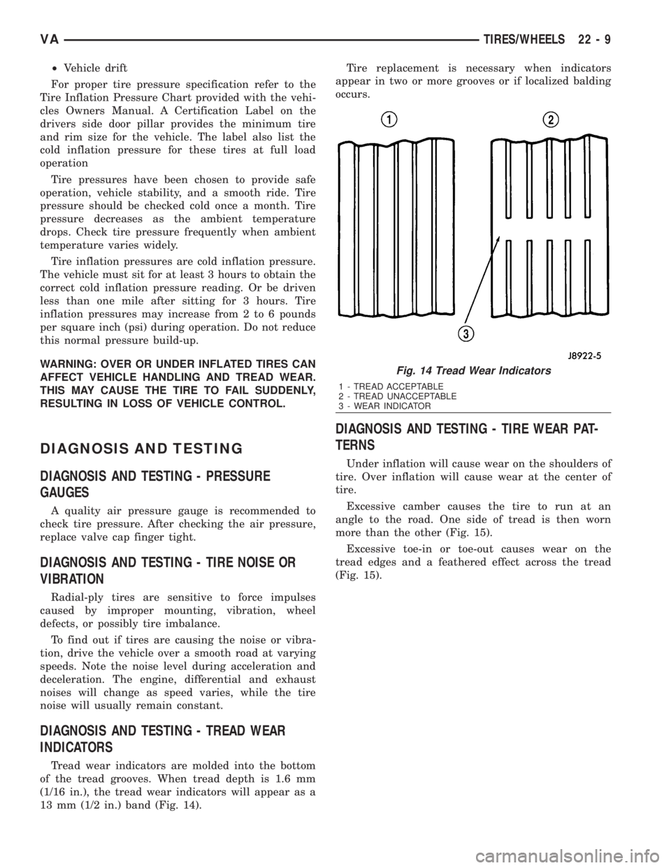
Tread wear indicators are molded into the bottom
of the tread grooves. When tread depth is 1.6 mm
(1/16 in.), the tread wear indicators will appear as a
13 mm (1/2 in.) band (Fig. 14).Tire replacement is necessary when indicators
appear in two or more grooves or if localized balding
occurs.
DIAGNOSIS AND TESTING - TIRE WEAR PAT-
TERNS
Under inflation will cause wear on the shoulders of
tire. Over inflation will cause wear at the center of
tire.
Excessive camber causes the tire to run at an
angle to the road. One side of tread is then worn
more than the other (Fig. 15).
Excessive toe-in or toe-out causes wear on the
tread edges and a feathered effect across the tread
(Fig. 15).
Fig. 14 Tread Wear Indicators
1 - TREAD ACCEPTABLE
2 - TREAD UNACCEPTABLE
3 - WEAR INDICATOR
VATIRES/WHEELS 22 - 9
Page 1995 of 2305
ADJUSTMENTS
ADJUSTMENT
SPECIFICATIONS
DESCRIPTION SPECIFICATION
Left and right hood gaps 5 0.5 mm
Flush offset for hood/
fender·1.0 mm
(1) Check hood to fender gap. Refer to the SPECI-
FICATIONS table.
(2) Loosen hinge to cowl bolts and adjust hood side
to side, if necessary.
(3) Tighten bolts to 23 N´m (17 ft. lbs.).
(4) Check hood to fender flushness. Refer to the
SPECIFICATIONS table.
(5) Loosen hinge to hood nuts and adjust hood up
and down, if necessary.
(6) Tighten nuts to 23 N´m (17 ft. lbs.).
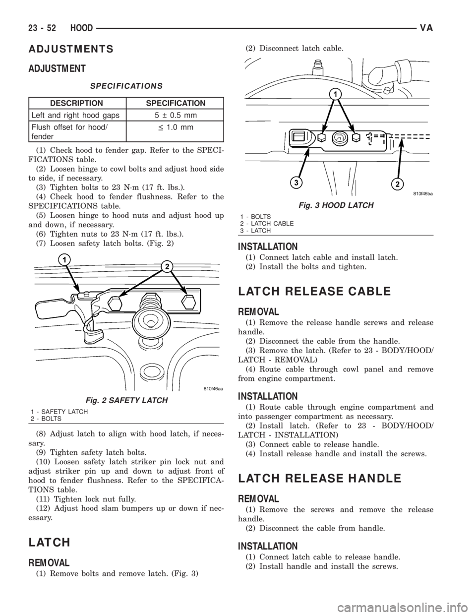
(7) Loosen safety latch bolts. (Fig. 2)
(8) Adjust latch to align with hood latch, if neces-
sary.
(9) Tighten safety latch bolts.
(10) Loosen safety latch striker pin lock nut and
adjust striker pin up and down to adjust front of
hood to fender flushness. Refer to the SPECIFICA-
TIONS table.
(11) Tighten lock nut fully.
(12) Adjust hood slam bumpers up or down if nec-
essary.
LATCH
REMOVAL
(1) Remove bolts and remove latch. (Fig. 3)(2) Disconnect latch cable.
INSTALLATION
(1) Connect latch cable and install latch.
(2) Install the bolts and tighten.
LATCH RELEASE CABLE
REMOVAL
(1) Remove the release handle screws and release
handle.
(2) Disconnect the cable from the handle.
(3) Remove the latch. (Refer to 23 - BODY/HOOD/
LATCH - REMOVAL)
(4) Route cable through cowl panel and remove
from engine compartment.
INSTALLATION
(1) Route cable through engine compartment and
into passenger compartment as necessary.
(2) Install latch. (Refer to 23 - BODY/HOOD/
LATCH - INSTALLATION)
(3) Connect cable to release handle.
(4) Install release handle and install the screws.
LATCH RELEASE HANDLE
REMOVAL
(1) Remove the screws and remove the release
handle.
(2) Disconnect the cable from handle.
INSTALLATION
(1) Connect latch cable to release handle.
(2) Install handle and install the screws.
Fig. 2 SAFETY LATCH
1 - SAFETY LATCH
2 - BOLTS
Fig. 3 HOOD LATCH
1 - BOLTS
2 - LATCH CABLE
3-LATCH
23 - 52 HOODVA
Page 2040 of 2305
When the outside air contains smoke, odors, high
humidity, or if rapid cooling is desired, interior air
can by recirculated by selecting the Recirculation
Mode with the mode control knob. The mode control
knob operates the recirculation door through use of a
vacuum actuator. When the Recirculation Mode is
selected, the recirculation door is closed to prevent
outside air from entering the passenger compart-
ment.
To maintain minimum evaporator temperature and
prevent evaporator freezing, an evaporator tempera-
ture sensor is used.
The A/C system is designed for the use of non-CFC,
R-134a refrigerant only and uses an expansion valve
to meter refrigerant flow to the evaporator.
DIAGNOSIS AND TESTING
A / C PERFORMANCE
The A/C system is designed to provide the passen-
ger compartment with low temperature and low
humidity air. The A/C evaporator, located in the
HVAC housing is cooled to temperatures near the
freezing point. As warm damp air passes over the
fins of the A/C evaporator, the air transfers its heat
to the refrigerant in the evaporator coils and the
moisture in the air condenses on the evaporator fins.
During periods of high heat and humidity, an A/C
system will be more effective in the Recirculation
mode (max-A/C). With the system in the Recircula-
tion mode, only air from the passenger compartment
passes through the A/C evaporator. As the passenger
compartment air dehumidifies, the A/C system per-
formance levels rise.
Humidity has an important bearing on the temper-
ature of the air delivered to the interior of the vehi-
cle. It is important to understand the effect that
humidity has on the performance of the A/C system.
When humidity is high, the A/C evaporator has to
perform a double duty. It must lower the air temper-
ature, and it must lower the temperature of the
moisture in the air that condenses on the evaporator
fins. Condensing the moisture in the air transfers
heat energy into the evaporator fins and coils. This
reduces the amount of heat the A/C evaporator can
absorb from the air. High humidity greatly reduces
the ability of the A/C evaporator to lower the temper-
ature of the air.
However, evaporator capacity used to reduce the
amount of moisture in the air is not wasted. Wring-
ing some of the moisture out of the air entering the
vehicle adds to the comfort of the passengers.
Although, an owner may expect too much from their
A/C system on humid days. A performance test is the
best way to determine whether the system is per-
forming up to design standards. This test also pro-
vides valuable clues as to the possible cause oftrouble with the A/C system. The ambient air tem-
perature in the location where the vehicle will be
tested must be a minimum of 21É C (70É F) for this
test.
A / C PERFORMANCE TEST
WARNING: Refer to the applicable warnings and
cautions for this system before performing the fol-
lowing operation (Refer to 24 - HEATING & AIR
CONDITIONING/PLUMBING - WARNINGS) and (Refer
to 24 - HEATING & AIR CONDITIONING/PLUMBING -
CAUTIONS). Failure to follow the warnings and cau-
tions could result in possible personal injury or
death.
NOTE: Very specific instructions and conditions
pertain to this procedure which are significantly dif-
ferent than procedures used in other vehicle appli-
cations. Follow each step in the order they are
presented. Do not skip steps or change conditions
from those stated or results will be adversely
affected and invalid.
NOTE: When connecting the service equipment
coupling to the line fitting, verify that the valve of
the coupling is fully closed. This will reduce the
amount of effort required to make the connection.
(1) Check for diagnostic trouble codes using a
DRBIIItscan tool. If no DTCs are found in the
engine control module (ECM), go to Step 2. If any
DTCs are found, repair as required, then proceed to
Step 2.
(2) Place the vehicle in the shade and operate the
heating-A/C system under the following conditions.
²Engine at idle at operating temperature
²All doors or windows open
²Transaxle in Neutral
²All A/C duct louvers open
²A/C-heater controls set to fresh air (NOT Recir-
culate), full cool, panel mode, high blower and with
A/C compressor engaged.
NOTE: The A/C compressor clutch is de-energized
under any of the following conditions:
²Restricted compressor (thermal fuse in the pul-
ley)
²Low pressure in the system
²Low evaporator temperature
²Hard acceleration (WOT)
²High coolant temperatures
(3) Insert a thermometer in the driver side center
panel air outlet and operate the A/C system until the
thermometer temperature stabilizes.
VAHEATING & AIR CONDITIONING 24 - 3
Page 2041 of 2305
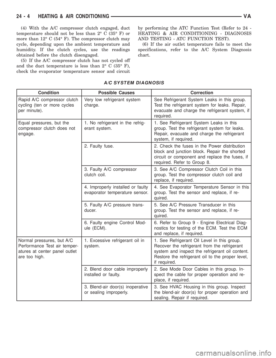
(4) With the A/C compressor clutch engaged, duct
temperature should not be less than 2É C (35É F) or
more than 12É C (54É F). The compressor clutch may
cycle, depending upon the ambient temperature and
humidity. If the clutch cycles, use the readings
obtained before the clutch disengaged.
(5) If the A/C compressor clutch has not cycled off
and the duct temperature is less than 2É C (35É F),
check the evaporator temperature sensor and circuitby performing the ATC Function Test (Refer to 24 -
HEATING & AIR CONDITIONING - DIAGNOSIS
AND TESTING - ATC FUNCTION TEST).
(6) If the air outlet temperature fails to meet the
specifications, refer to the A/C System Diagnosis
chart.
A/C SYSTEM DIAGNOSIS
Condition Possible Causes Correction
Rapid A/C compressor clutch
cycling (ten or more cycles
per minute).Very low refrigerant system
charge.See Refrigerant System Leaks in this group.
Test the refrigerant system for leaks. Repair,
evacuate and charge the refrigerant system, if
required.
Equal pressures, but the
compressor clutch does not
engage.1. No refrigerant in the refrig-
erant system.1. See Refrigerant System Leaks in this
group. Test the refrigerant system for leaks.
Repair, evacuate and charge the refrigerant
system, if required.
2. Faulty fuse. 2. Check the fuses in the Power distribution
block and junction block. Repair the shorted
circuit or component and replace the fuses, if
required. Refer to Group 8.
3. Faulty A/C compressor
clutch coil.3. See A/C Compressor Clutch Coil in this
group. Test the compressor clutch coil and
replace, if required.
4. Improperly installed or faulty
evaporator temperature sensor.4. See Evaporator Temperature Sensor in this
group. Test the sensor and replace, if re-
quired.
5. Faulty A/C pressure trans-
ducer.5. See A/C Pressure Transducer in this
group. Test the sensor and replace, if re-
quired.
6. Faulty engine Control Mod-
ule (ECM).6. Refer to Group 9 - Engine Electrical Diag-
nostics for testing of the ECM. Test the ECM
and replace, if required.
Normal pressures, but A/C
Performance Test air temper-
atures at center panel outlet
are too high.1. Excessive refrigerant oil in
system.1. See Refrigerant Oil Level in this group.
Recover the refrigerant from the refrigerant
system and inspect the refrigerant oil content.
Restore the refrigerant oil to the proper level,
if required.
2. Blend door cable improperly
installed or faulty.2. See Mode Door Cables in this group. In-
spect the cable for proper operation and re-
place, if required.
3. Blend-air door(s) inoperative
or sealing improperly.3. See HVAC Housing in this group. Inspect
the blend-air door(s) for proper operation and
sealing. Repair if required.
24 - 4 HEATING & AIR CONDITIONINGVA
Page 2042 of 2305
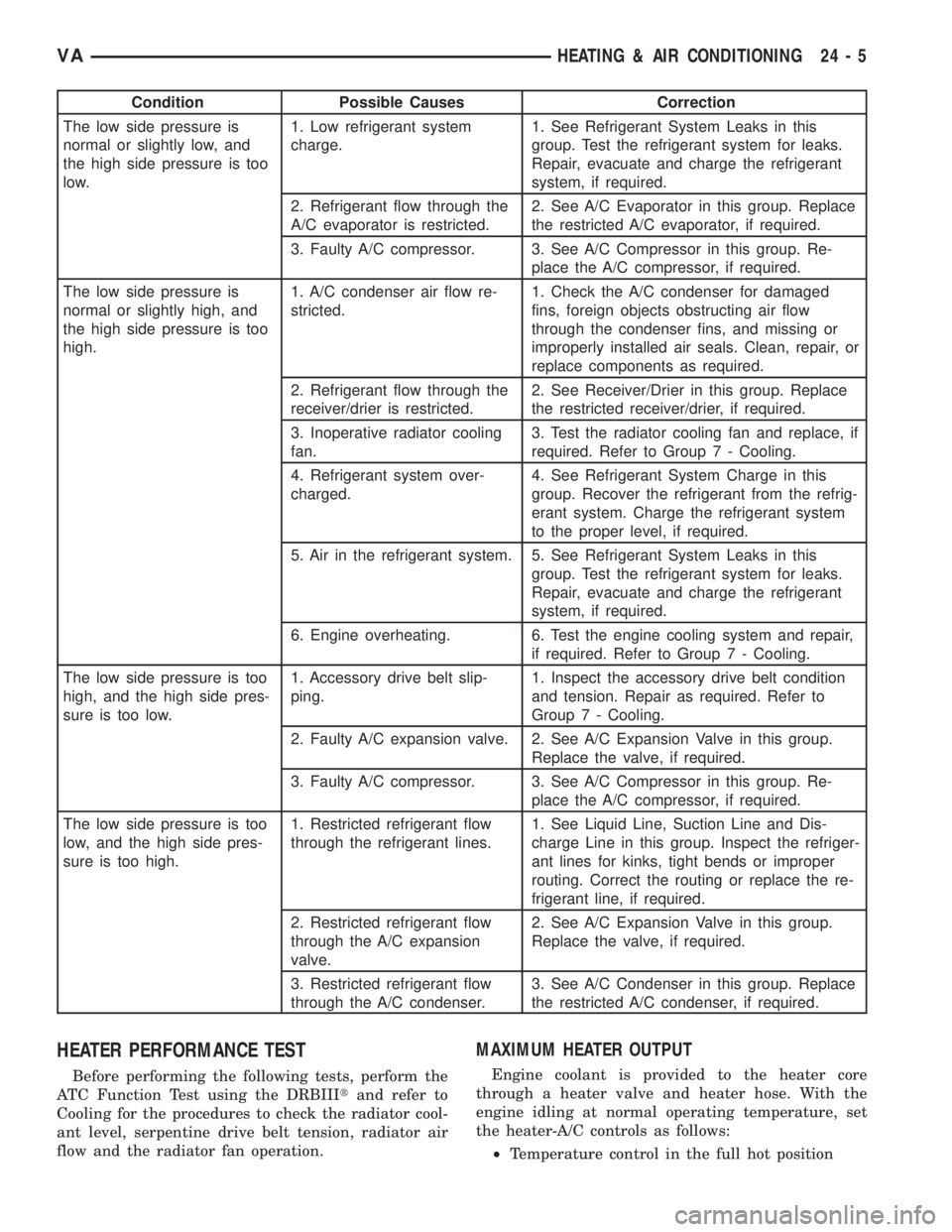
Condition Possible Causes Correction
The low side pressure is
normal or slightly low, and
the high side pressure is too
low.1. Low refrigerant system
charge.1. See Refrigerant System Leaks in this
group. Test the refrigerant system for leaks.
Repair, evacuate and charge the refrigerant
system, if required.
2. Refrigerant flow through the
A/C evaporator is restricted.2. See A/C Evaporator in this group. Replace
the restricted A/C evaporator, if required.
3. Faulty A/C compressor. 3. See A/C Compressor in this group. Re-
place the A/C compressor, if required.
The low side pressure is
normal or slightly high, and
the high side pressure is too
high.1. A/C condenser air flow re-
stricted.1. Check the A/C condenser for damaged
fins, foreign objects obstructing air flow
through the condenser fins, and missing or
improperly installed air seals. Clean, repair, or
replace components as required.
2. Refrigerant flow through the
receiver/drier is restricted.2. See Receiver/Drier in this group. Replace
the restricted receiver/drier, if required.
3. Inoperative radiator cooling
fan.3. Test the radiator cooling fan and replace, if
required. Refer to Group 7 - Cooling.
4. Refrigerant system over-
charged.4. See Refrigerant System Charge in this
group. Recover the refrigerant from the refrig-
erant system. Charge the refrigerant system
to the proper level, if required.
5. Air in the refrigerant system. 5. See Refrigerant System Leaks in this
group. Test the refrigerant system for leaks.
Repair, evacuate and charge the refrigerant
system, if required.
6. Engine overheating. 6. Test the engine cooling system and repair,
if required. Refer to Group 7 - Cooling.
The low side pressure is too
high, and the high side pres-
sure is too low.1. Accessory drive belt slip-
ping.1. Inspect the accessory drive belt condition
and tension. Repair as required. Refer to
Group 7 - Cooling.
2. Faulty A/C expansion valve. 2. See A/C Expansion Valve in this group.
Replace the valve, if required.
3. Faulty A/C compressor. 3. See A/C Compressor in this group. Re-
place the A/C compressor, if required.
The low side pressure is too
low, and the high side pres-
sure is too high.1. Restricted refrigerant flow
through the refrigerant lines.1. See Liquid Line, Suction Line and Dis-
charge Line in this group. Inspect the refriger-
ant lines for kinks, tight bends or improper
routing. Correct the routing or replace the re-
frigerant line, if required.
2. Restricted refrigerant flow
through the A/C expansion
valve.2. See A/C Expansion Valve in this group.
Replace the valve, if required.
3. Restricted refrigerant flow
through the A/C condenser.3. See A/C Condenser in this group. Replace
the restricted A/C condenser, if required.
HEATER PERFORMANCE TEST
Before performing the following tests, perform the
ATC Function Test using the DRBIIItand refer to
Cooling for the procedures to check the radiator cool-
ant level, serpentine drive belt tension, radiator air
flow and the radiator fan operation.
MAXIMUM HEATER OUTPUT
Engine coolant is provided to the heater core
through a heater valve and heater hose. With the
engine idling at normal operating temperature, set
the heater-A/C controls as follows:
²Temperature control in the full hot position
VAHEATING & AIR CONDITIONING 24 - 5