oil change MERCEDES-BENZ SPRINTER 2006 Owner's Manual
[x] Cancel search | Manufacturer: MERCEDES-BENZ, Model Year: 2006, Model line: SPRINTER, Model: MERCEDES-BENZ SPRINTER 2006Pages: 2305, PDF Size: 48.12 MB
Page 1627 of 2305
(19) Fill the cooing system with proper coolant, to
the proper level (Refer to 7 - COOLING/ENGINE/
COOLANT - STANDARD PROCEDURE).
(20) Connect negative battery cable.
WARNING: USE EXTREME CAUTION WHEN THE
ENGINE IS OPERATING. DO NOT STAND IN A
DIRECT LINE WITH THE FAN. DO NOT PUT YOUR
HANDS NEAR THE PULLEYS, BELTS, OR FAN. DO
NOT WEAR LOOSE CLOTHES.
WARNING: (Refer to 14 - FUEL SYSTEM - WARN-
ING).
(21) Start the engine and inspect for leaks.
PISTON RINGS
STANDARD PROCEDURE - PISTON RING FIT-
TING
(1) Carefully clean the carbon from all ring
grooves. Oil drain openings in the oil ring groove and
pin boss must be clear. DO NOT remove metal from
the grooves or lands. This will change ring-to-groove
clearances and will damage the ring-to-land seating.
(2) Be sure the piston ring grooves are free of
nicks and burrs.
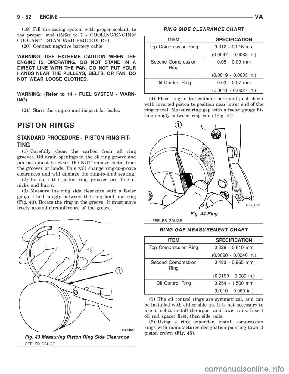
(3) Measure the ring side clearance with a feeler
gauge fitted snugly between the ring land and ring
(Fig. 43). Rotate the ring in the groove. It must move
freely around circumference of the groove.
RING SIDE CLEARANCE CHART
ITEM SPECIFICATION
Top Compression Ring 0.012 - 0.016 mm
(0.0047 - 0.0063 in.)
Second Compression
Ring0.05 - 0.09 mm
(0.0019 - 0.0035 in.)
Oil Control Ring 0.03 - 0.07 mm
(0.0011 - 0.0027 in.)
(4) Place ring in the cylinder bore and push down
with inverted piston to position near lower end of the
ring travel. Measure ring gap with a feeler gauge fit-
ting snugly between ring ends (Fig. 44).
RING GAP MEASUREMENT CHART
ITEM SPECIFICATION
Top Compression Ring 0.229 - 0.610 mm
(0.0090 - 0.0240 in.)
Second Compression
Ring0.483 - 0.965 mm
(0.0190 - 0.080 in.)
Oil Control Ring 0.254 - 1.500 mm
(0.010 - 0.060 in.)
(5) The oil control rings are symmetrical, and can
be installed with either side up. It is not necessary to
use a tool to install the upper and lower rails. Insert
oil rail spacer first, then side rails.
(6) Using a ring expander, install compression
rings with manufactures designation pointing toward
piston crown (Fig. 45).
Fig. 43 Measuring Piston Ring Side Clearance
1 - FEELER GAUGE
Fig. 44 Ring
1 - FEELER GAUGE
9 - 52 ENGINEVA
Page 1638 of 2305
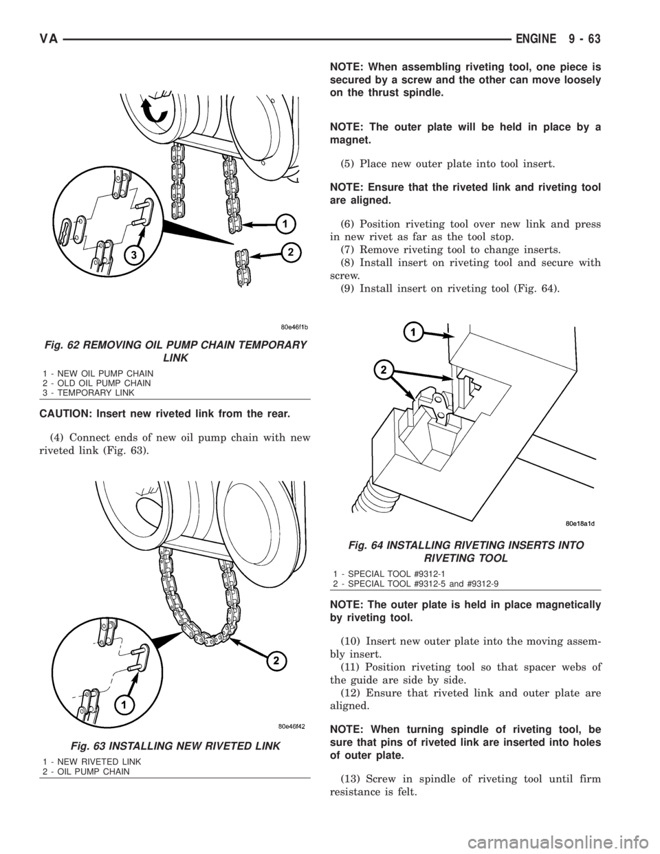
CAUTION: Insert new riveted link from the rear.
(4) Connect ends of new oil pump chain with new
riveted link (Fig. 63).NOTE: When assembling riveting tool, one piece is
secured by a screw and the other can move loosely
on the thrust spindle.
NOTE: The outer plate will be held in place by a
magnet.
(5) Place new outer plate into tool insert.
NOTE: Ensure that the riveted link and riveting tool
are aligned.
(6) Position riveting tool over new link and press
in new rivet as far as the tool stop.
(7) Remove riveting tool to change inserts.
(8) Install insert on riveting tool and secure with
screw.
(9) Install insert on riveting tool (Fig. 64).
NOTE: The outer plate is held in place magnetically
by riveting tool.
(10) Insert new outer plate into the moving assem-
bly insert.
(11) Position riveting tool so that spacer webs of
the guide are side by side.
(12) Ensure that riveted link and outer plate are
aligned.
NOTE: When turning spindle of riveting tool, be
sure that pins of riveted link are inserted into holes
of outer plate.
(13) Screw in spindle of riveting tool until firm
resistance is felt.
Fig. 62 REMOVING OIL PUMP CHAIN TEMPORARY
LINK
1 - NEW OIL PUMP CHAIN
2 - OLD OIL PUMP CHAIN
3 - TEMPORARY LINK
Fig. 63 INSTALLING NEW RIVETED LINK
1 - NEW RIVETED LINK
2 - OIL PUMP CHAIN
Fig. 64 INSTALLING RIVETING INSERTS INTO
RIVETING TOOL
1 - SPECIAL TOOL #9312-1
2 - SPECIAL TOOL #9312-5 and #9312-9
VAENGINE 9 - 63
Page 1639 of 2305
(14) Remove riveting tool.
(15) Turn over tool moving assembly insert to the
riveting profile.
NOTE: Rivet pins of the riveted link individually.
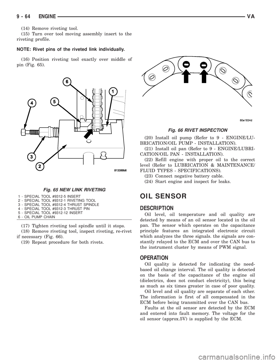
(16) Position riveting tool exactly over middle of
pin (Fig. 65).
(17) Tighten riveting tool spindle until it stops.
(18) Remove riveting tool, inspect riveting, re-rivet
if necessary (Fig. 66).
(19) Repeat procedure for both rivets.(20) Install oil pump (Refer to 9 - ENGINE/LU-
BRICATION/OIL PUMP - INSTALLATION).
(21) Install oil pan (Refer to 9 - ENGINE/LUBRI-
CATION/OIL PAN - INSTALLATION).
(22) Refill engine with proper oil to the correct
level (Refer to LUBRICATION & MAINTENANCE/
FLUID TYPES - SPECIFICATIONS).
(23) Connect negative battery cable.
(24) Start engine and inspect for leaks.
OIL SENSOR
DESCRIPTION
Oil level, oil temperature and oil quality are
detected by means of an oil sensor located in the oil
pan. The sensor which operates on the capacitance
principle features an integrated electronic circuit
which analyzes the three signals. the signals are con-
stantly relayed to the ECM and over the CAN bus to
the instrument cluster by means of PWM signal.
OPERATION
Oil quality is detected for indicating the need-
based oil change interval. The oil quality is detected
on the basis of the capacitance of the engine oil
(dielectrics, does not conduct electricity), this being
as much as six times greater in case of poor quality.
Oil level and oil quality are separate of each other.
The information is first of all compensated in the
ECM before being transmitted over the CAN bus.
Faults at the oil sensor are detected by the ECM
and entered into fault memory. The voltage for the
oil sensor (approx.5V) is supplied by the ECM.
Fig. 65 NEW LINK RIVETING
1 - SPECIAL TOOL #9312-5 INSERT
2 - SPECIAL TOOL #9312-1 RIVETING TOOL
3 - SPECIAL TOOL #9312-4 THRUST SPINDLE
4 - SPECIAL TOOL #9312-3 THRUST PIN
5 - SPECIAL TOOL #9312-12 INSERT
6 - OIL PUMP CHAIN
Fig. 66 RIVET INSPECTION
9 - 64 ENGINEVA
Page 1645 of 2305
(8) Install the exhaust hanger fasteners at the
muffler.
(9) Tighten the exhaust hanger bracket to engine
block.
(10) Install the turbocharger support bracket.
(11) Lower the vehicle.
(12) Install the air cleaner duct to the turbo-
charger (Fig. 71).
(13) Install the exhaust heat shield.
(14) Connect the negative battery cable.
TIMING CHAIN COVER
REMOVAL
WARNING: DO NOT OPEN COOLING SYSTEM
UNLESS TEMPERATURE IS BELOW 90ÉC (194ÉF).
OPEN CAP SLOWLY TO RELEASE PRESSURE.
STORE COOLANT IN APPROVED CONTAINER
ONLY. RISK OF INJURY TO SKIN AND EYES FROM
SCALDING COOLANT. WEAR PROTECTIVE
GLOVES, CLOTHING AND EYE WEAR.
(1) Disconnect negative battery cable.
NOTE: Rotate engine on crankshaft. DO NOT crank
the engine at the bolt of the camshaft sprocket.
NOTE: DO NOT crank engine back.
(2) Position piston of cylinder 1 to ignition TDC.
Markings on the camshaft bearing cap must be
aligned.
(3) Drain coolant (Refer to 7 - COOLING/ENGINE/
COOLANT - STANDARD PROCEDURE).
(4) Install retaining lock for crankshaft/starter
ring gear (Refer to 9 - ENGINE/ENGINE BLOCK/
FLEX PLATE - INSTALLATION).
(5) Drain engine oil.
(6) Remove the oil filter to allow the oil to flow off
into the oil pan.
(7) Remove the radiator assembly (Refer to 7 -
COOLING/ENGINE/RADIATOR - REMOVAL).
(8) Remove engine cover (Refer to 9 - ENGINE -
REMOVAL).
(9) Remove front cover at cylinder head (Refer to 9
- ENGINE/CYLINDER HEAD - REMOVAL).
(10) Remove accessory drive belt.
(11) Remove the high pressure fuel pump (Refer to
14 - FUEL SYSTEM/FUEL DELIVERY/FUEL PUMP
- REMOVAL).
(12) Remove water pump (Refer to 7 - COOLING/
ENGINE/WATER PUMP - REMOVAL).
(13) Remove accessory drive belt pulley and vibra-
tion damper (Refer to 9 - ENGINE/ENGINE BLOCK/
VIBRATION DAMPER - REMOVAL).
(14) Remove the power steering pump.NOTE: NO NOT open the air conditioning system.
(15) Unplug AC compressor electrical connector
and unbolt AC compressor. Relocate in lower engine
compartmentwith outopening the system.
(16) Remove the generator with wiring attached
and relocate somewhere in the engine compartment.
(17) Install engine support fixture.
(18) Remove the oil pan.
(19) Detach the coolant hose to oil-water heat
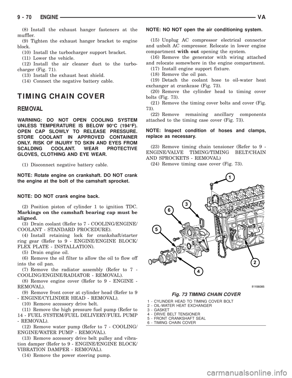
exchanger at crankcase (Fig. 73).
(20) Remove the cylinder head to timing cover
bolts (Fig. 73).
(21) Remove the timing cover bolts and cover (Fig.
73).
(22) Remove remaining ancillary components
attached to the timing case cover (Fig. 73).
NOTE: Inspect condition of hoses and clamps,
replace as necessary.
(23) Remove timing chain tensioner (Refer to 9 -
ENGINE/VALVE TIMING/TIMING BELT/CHAIN
AND SPROCKETS - REMOVAL)
(24) Remove timing case cover (Fig. 73).
Fig. 73 TIMING CHAIN COVER
1 - CYLINDER HEAD TO TIMING COVER BOLT
2 - OIL-WATER HEAT EXCHANGER
3 - GASKET
4 - DRIVE BELT TENSIONER
5 - FRONT CRANKSHAFT SEAL
6 - TIMING CHAIN COVER
9 - 70 ENGINEVA
Page 1646 of 2305
INSTALLATION
CAUTION: Care must be taken to closley inspect
the gasket area around the time case cover to cyl-
inder head gasket coolant port. If damage is found,
replace the cylinder head gasket. Failure to do so
may result in engine damage.
NOTE: Thoroughly clean all mating surfaces with
the appropriate solvents to assure that no grease or
oil is present during assembly.
(1) Inspect cylinder head gasket and oil pan gas-
ket. If damaged, replace.
(2) Replace the front crankshaft seal (Refer to 9 -
ENGINE/ENGINE BLOCK/CRANKSHAFT OIL
SEAL - FRONT - INSTALLATION).
(3) Install ancillary components to timing case
cover.
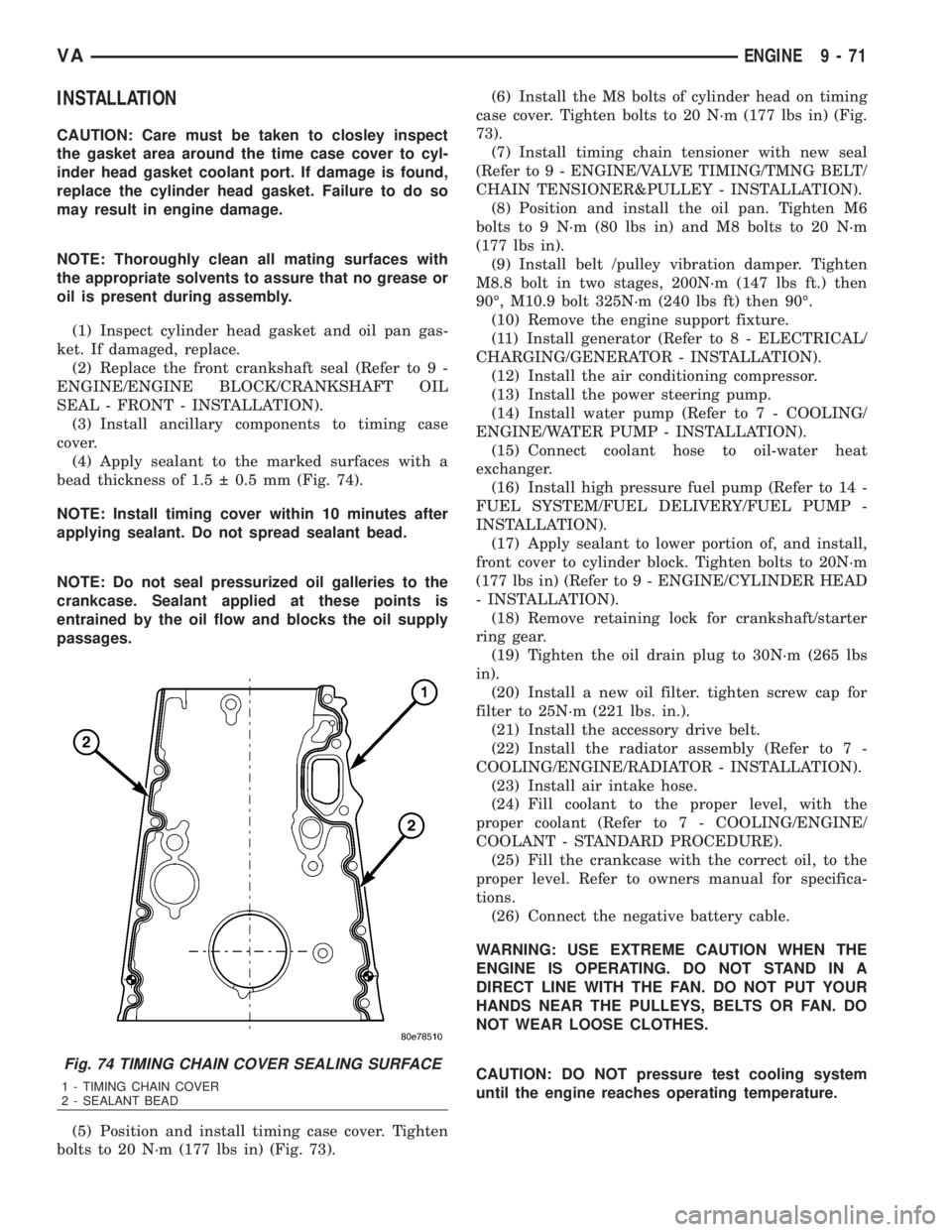
(4) Apply sealant to the marked surfaces with a
bead thickness of 1.5 0.5 mm (Fig. 74).
NOTE: Install timing cover within 10 minutes after
applying sealant. Do not spread sealant bead.
NOTE: Do not seal pressurized oil galleries to the
crankcase. Sealant applied at these points is
entrained by the oil flow and blocks the oil supply
passages.
(5) Position and install timing case cover. Tighten
bolts to 20 N´m (177 lbs in) (Fig. 73).(6) Install the M8 bolts of cylinder head on timing
case cover. Tighten bolts to 20 N´m (177 lbs in) (Fig.
73).
(7) Install timing chain tensioner with new seal
(Refer to 9 - ENGINE/VALVE TIMING/TMNG BELT/
CHAIN TENSIONER&PULLEY - INSTALLATION).
(8) Position and install the oil pan. Tighten M6
bolts to 9 N´m (80 lbs in) and M8 bolts to 20 N´m
(177 lbs in).
(9) Install belt /pulley vibration damper. Tighten
M8.8 bolt in two stages, 200N´m (147 lbs ft.) then
90É, M10.9 bolt 325N´m (240 lbs ft) then 90É.
(10) Remove the engine support fixture.
(11) Install generator (Refer to 8 - ELECTRICAL/
CHARGING/GENERATOR - INSTALLATION).
(12) Install the air conditioning compressor.
(13) Install the power steering pump.
(14) Install water pump (Refer to 7 - COOLING/
ENGINE/WATER PUMP - INSTALLATION).
(15) Connect coolant hose to oil-water heat
exchanger.
(16) Install high pressure fuel pump (Refer to 14 -
FUEL SYSTEM/FUEL DELIVERY/FUEL PUMP -
INSTALLATION).
(17) Apply sealant to lower portion of, and install,
front cover to cylinder block. Tighten bolts to 20N´m
(177 lbs in) (Refer to 9 - ENGINE/CYLINDER HEAD
- INSTALLATION).
(18) Remove retaining lock for crankshaft/starter
ring gear.
(19) Tighten the oil drain plug to 30N´m (265 lbs
in).
(20) Install a new oil filter. tighten screw cap for
filter to 25N´m (221 lbs. in.).
(21) Install the accessory drive belt.
(22) Install the radiator assembly (Refer to 7 -
COOLING/ENGINE/RADIATOR - INSTALLATION).
(23) Install air intake hose.
(24) Fill coolant to the proper level, with the
proper coolant (Refer to 7 - COOLING/ENGINE/
COOLANT - STANDARD PROCEDURE).
(25) Fill the crankcase with the correct oil, to the
proper level. Refer to owners manual for specifica-
tions.
(26) Connect the negative battery cable.
WARNING: USE EXTREME CAUTION WHEN THE
ENGINE IS OPERATING. DO NOT STAND IN A
DIRECT LINE WITH THE FAN. DO NOT PUT YOUR
HANDS NEAR THE PULLEYS, BELTS OR FAN. DO
NOT WEAR LOOSE CLOTHES.
CAUTION: DO NOT pressure test cooling system
until the engine reaches operating temperature.
Fig. 74 TIMING CHAIN COVER SEALING SURFACE
1 - TIMING CHAIN COVER
2 - SEALANT BEAD
VAENGINE 9 - 71
Page 1654 of 2305
(4) Remove assembly locking element, assembly
outer plate and assembly link.
CAUTION: Cover timing case recesses to prevent
foreign material from entering engine.
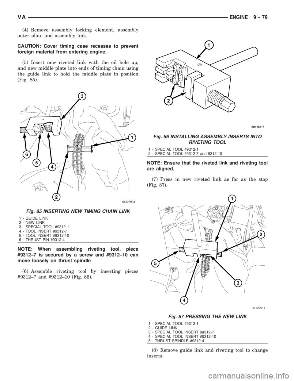
(5) Insert new riveted link with the oil hole up,
and new middle plate into ends of timing chain using
the guide link to hold the middle plate in position
(Fig. 85).
NOTE: When assembling riveting tool, piece
#9312±7 is secured by a screw and #9312±10 can
move loosely on thrust spindle
(6) Assemble riveting tool by inserting pieces
#9312±7 and #9312±10 (Fig. 86).NOTE: Ensure that the riveted link and riveting tool
are aligned.
(7) Press in new riveted link as far as the stop
(Fig. 87).
(8) Remove guide link and riveting tool to change
inserts.
Fig. 85 INSERTING NEW TIMING CHAIN LINK
1 - GUIDE LINK
2 - NEW LINK
3 - SPECIAL TOOL #9312-1
4 - TOOL INSERT #9312-7
5 - TOOL INSERT #9312-10
6 - THRUST PIN #9312-4
Fig. 86 INSTALLING ASSEMBLY INSERTS INTO
RIVETING TOOL
1 - SPECIAL TOOL #9312-1
2 - SPECIAL TOOL #9312-7 and 9312-10
Fig. 87 PRESSING THE NEW LINK
1 - SPECIAL TOOL #9312-1
2 - GUIDE LINK
3 - SPECIAL TOOL INSERT 9#312-7
4 - SPECIAL TOOL INSERT #9312-10
5 - THRUST SPINDLE #9312-4
VAENGINE 9 - 79
Page 1730 of 2305
STEERING
TABLE OF CONTENTS
page page
STEERING
DESCRIPTION..........................1
OPERATION............................1
DIAGNOSIS AND TESTING - POWER
STEERING SYSTEM....................1COLUMN................................4
GEAR..................................7
LINKAGE................................9
PUMP..................................11
STEERING
DESCRIPTION
CAUTION: Use approved fluid only in the power
steering system (Refer to LUBRICATION & MAINTE-
NANCE/FLUID TYPES - DESCRIPTION). No other
power steering or automatic transmission fluid is to
be used in the system. Damage may result to the
power steering pump and system if any other fluid
is used, and do not overfill.
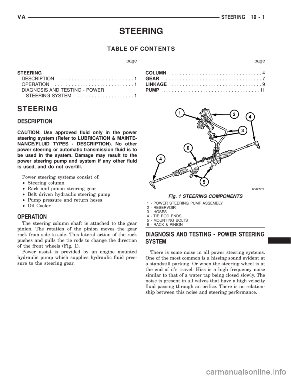
Power steering systems consist of:
²Steering column
²Rack and pinion steering gear
²Belt driven hydraulic steering pump
²Pump pressure and return hoses
²Oil Cooler
OPERATION
The steering column shaft is attached to the gear
pinion. The rotation of the pinion moves the gear
rack from side-to-side. This lateral action of the rack
pushes and pulls the tie rods to change the direction
of the front wheels (Fig. 1).
Power assist is provided by an engine mounted
hydraulic pump which supplies hydraulic fluid pres-
sure to the steering gear.
DIAGNOSIS AND TESTING - POWER STEERING
SYSTEM
There is some noise in all power steering systems.
One of the most common is a hissing sound evident at
a standstill parking. Or when the steering wheel is at
the end of it's travel. Hiss is a high frequency noise
similar to that of a water tap being closed slowly. The
noise is present in all valves that have a high velocity
fluid passing through an orifice. There is no relation-
ship between this noise and steering performance.
Fig. 1 STEERING COMPONENTS
1 - POWER STEERING PUMP ASSEMBLY
2 - RESERVOIR
3 - HOSES
4 - TIE ROD ENDS
5 - MOUNTING BOLTS
6 - RACK & PINION
VASTEERING 19 - 1
Page 1747 of 2305
²Increased service life and reliability.
²Lower maintenance costs.
TRANSMISSION IDENTIFICATION
The transmission can be generically identified
visually by the presence of a round 13-way connector
located near the front corner of the transmission oil
pan, on the right side. Specific transmission informa-
tion can be found stamped into a pad on the left side
of the transmission, above the oil pan rail.
TRANSMISSION GEAR RATIOS
The gear ratios for the NAG1 automatic transmis-
sion are as follows:
1st Gear............................3.59:1
2nd Gear............................2.19:1
3rd Gear............................1.41:1
4th Gear............................1.00:1
5th Gear............................0.83:1
Reverse.............................3.16:1
TRANSMISSION HOUSING
The converter housing and transmission are made
from a light alloy. These are bolted together and cen-
tered via the outer multi-disc carrier of multi-disc
holding clutch, B1. A coated intermediate plate pro-
vides the sealing. The oil pump and the outer multi-
disc carrier of the multi-disc holding clutch, B1, are
bolted to the converter housing. The stator shaft is
pressed into it and prevented from rotating by
splines. The electrohydraulic unit is bolted to the
transmission housing from underneath. A sheet
metal steel oil pan forms the closure.
MECHANICAL SECTION
The mechanical section consists of a input shaft,
output shaft, a sun gear shaft, and three planetary
gear sets which are coupled to each other. The plan-
etary gear sets each have four planetary pinion
gears. The oil pressure for the torque converter
lock-up clutch and clutch K2 is supplied through
bores in the input shaft. The oil pressure to clutch
K3 is transmitted through the output shaft. The
lubricating oil is distributed through additional bores
in both shafts. All the bearing points of the gear sets,
as well as the freewheeling clutches and actuators,
are supplied with lubricating oil. The parking lock
gear is connected to the output shaft via splines.
Freewheeling clutches F1 and F2 are used to opti-
mize the shifts. The front freewheel, F1, is supported
on the extension of the stator shaft on the transmis-
sion side and, in the locking direction, connects the
sun gear of the front planetary gear set to the trans-
mission housing. In the locking direction, the rear
freewheeling clutch, F2, connects the sun gear of the
center planetary gear set to the sun gear of the rear
planetary gear set.
ELECTROHYDRAULIC CONTROL UNIT
The electrohydraulic control unit comprises the
shift plate made from light alloy for the hydraulic
control and an electrical control unit. The electrical
control unit comprises of a supporting body made of
plastic, into which the electrical components are
assembled. The supporting body is mounted on the
shift plate and screwed to it.
Strip conductors inserted into the supporting body
make the connection between the electrical compo-
nents and a plug connector. The connection to the
wiring harness on the vehicle and the transmission
control module (TCM) is produced via this 13-pin
plug connector with a bayonet lock.
SHIFT GROUPS
The hydraulic control components (including actua-
tors) which are responsible for the pressure distribu-
tion before, during, and after a gear change are
described as a shift group. Each shift group contains
a command valve, a holding pressure shift valve, a
shift pressure shift valve, overlap regulating valve,
and a solenoid.
The hydraulic system contains three shift groups:
1-2/4-5, 2-3, and 3-4. Each shift group can also be
described as being in one of two possible states. The
active shift group is described as being in the shift
phase when it is actively engaging/disengaging a
clutch combination. The 1-2/4-5 shift group control
the B1 and K1 clutches. The 2-3 shift group controls
the K2 and K3 clutches. The 3-4 shift group controls
the K3 and B2 clutches.
OPERATION
The transmission control is divided into the elec-
tronic and hydraulic transmission control functions.
While the electronic transmission control is responsi-
ble for gear selection and for matching the pressures
to the torque to be transmitted, the transmission's
power supply control occurs via hydraulic elements
in the electrohydraulic control module. The oil supply
to the hydraulic elements, such as the hydrodynamic
torque converter, the shift elements and the hydrau-
lic transmission control, is provided by way of an oil
pump connected with the torque converter.
The Transmission Control Module (TCM) allows for
the precise adaptation of pressures to the correspond-
ing operating conditions and to the engine output
during the gearshift phase, resulting in a noticeable
improvement in shift quality. The engine speed limit
can be reached in the individual gears at full throttle
and kickdown. The shift range can be changed in the
forward gears while driving, but the TCM employs a
downshift safeguard to prevent over-revving the
engine. The system offers the additional advantage of
21 - 4 AUTOMATIC TRANSMISSION NAG1 - SERVICE INFORMATIONVA
Page 1790 of 2305
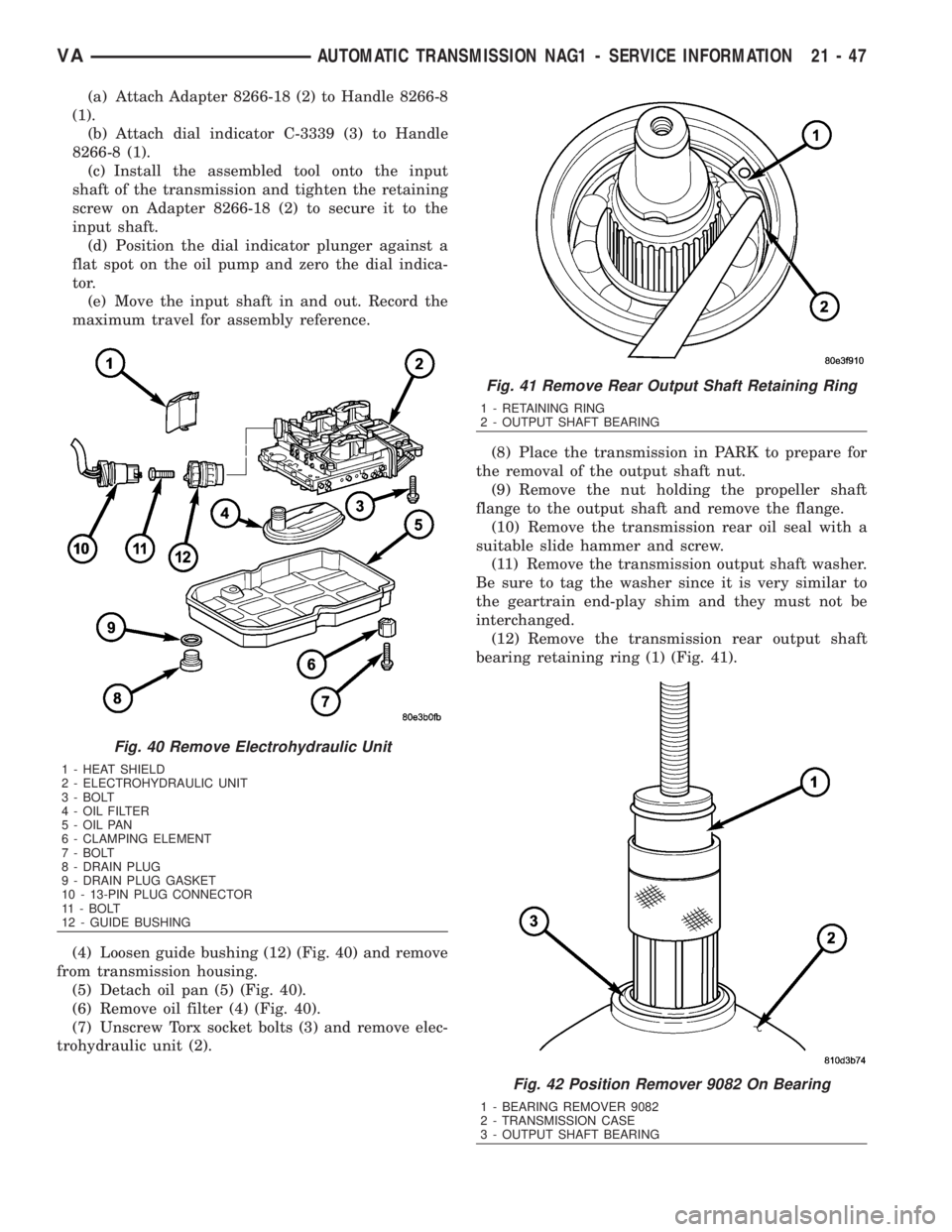
(a) Attach Adapter 8266-18 (2) to Handle 8266-8
(1).
(b) Attach dial indicator C-3339 (3) to Handle
8266-8 (1).
(c) Install the assembled tool onto the input
shaft of the transmission and tighten the retaining
screw on Adapter 8266-18 (2) to secure it to the
input shaft.
(d) Position the dial indicator plunger against a
flat spot on the oil pump and zero the dial indica-
tor.
(e) Move the input shaft in and out. Record the
maximum travel for assembly reference.
(4) Loosen guide bushing (12) (Fig. 40) and remove
from transmission housing.
(5) Detach oil pan (5) (Fig. 40).
(6) Remove oil filter (4) (Fig. 40).
(7) Unscrew Torx socket bolts (3) and remove elec-
trohydraulic unit (2).(8) Place the transmission in PARK to prepare for
the removal of the output shaft nut.
(9) Remove the nut holding the propeller shaft
flange to the output shaft and remove the flange.
(10) Remove the transmission rear oil seal with a
suitable slide hammer and screw.
(11) Remove the transmission output shaft washer.
Be sure to tag the washer since it is very similar to
the geartrain end-play shim and they must not be
interchanged.
(12) Remove the transmission rear output shaft
bearing retaining ring (1) (Fig. 41).
Fig. 40 Remove Electrohydraulic Unit
1 - HEAT SHIELD
2 - ELECTROHYDRAULIC UNIT
3 - BOLT
4 - OIL FILTER
5 - OIL PAN
6 - CLAMPING ELEMENT
7 - BOLT
8 - DRAIN PLUG
9 - DRAIN PLUG GASKET
10 - 13-PIN PLUG CONNECTOR
11 - BOLT
12 - GUIDE BUSHING
Fig. 41 Remove Rear Output Shaft Retaining Ring
1 - RETAINING RING
2 - OUTPUT SHAFT BEARING
Fig. 42 Position Remover 9082 On Bearing
1 - BEARING REMOVER 9082
2 - TRANSMISSION CASE
3 - OUTPUT SHAFT BEARING
VAAUTOMATIC TRANSMISSION NAG1 - SERVICE INFORMATION 21 - 47
Page 1877 of 2305
To avoid overfilling transmission after a fluid
change or overhaul, perform the following procedure:
(1) Verify that the vehicle is parked on a level sur-
face.
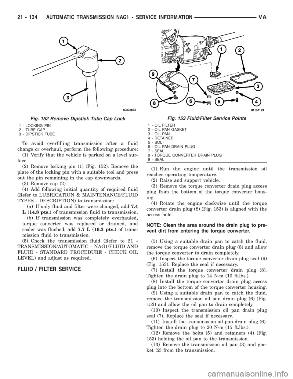
(2) Remove locking pin (1) (Fig. 152). Remove the
plate of the locking pin with a suitable tool and press
out the pin remaining in the cap downwards.
(3) Remove cap (2).
(4) Add following initial quantity of required fluid
(Refer to LUBRICATION & MAINTENANCE/FLUID
TYPES - DESCRIPTION) to transmission:
(a) If only fluid and filter were changed, add7.4
L (14.8 pts.)of transmission fluid to transmission.
(b) If transmission was completely overhauled,
torque converter was replaced or drained, and
cooler was flushed, add7.7 L (16.3 pts.)of trans-
mission fluid to transmission.
(5) Check the transmission fluid (Refer to 21 -
TRANSMISSION/AUTOMATIC - NAG1/FLUID AND
FLUID - STANDARD PROCEDURE - CHECK OIL
LEVEL) and adjust as required.
FLUID / FILTER SERVICE
(1) Run the engine until the transmission oil
reaches operating temperature.
(2) Raise and support vehicle.
(3) Remove the torque converter drain plug access
plug from the bottom of the torque converter hous-
ing.
(4) Rotate the engine clockwise until the torque
converter drain plug (8) (Fig. 153) is aligned with the
access hole.
NOTE: Clean the area around the drain plug to pre-
vent dirt from entering the torque converter.
(5) Using a suitable drain pan to catch the fluid,
remove the torque converter drain plug (8) and allow
the torque converter to drain completely.
(6) Inspect the torque converter drain plug seal (9)
(Fig. 153). Replace the seal if necessary.
(7) Install the torque converter drain plug (8).
Tighten the drain plug to 14 N´m (10 ft.lbs.).
(8) Install the torque converter drain plug access
plug into the bottom of the torque converter housing.
(9) Using a suitable drain pan to catch the fluid,
remove the transmission oil pan drain plug (6) (Fig.
153) and allow the oil pan to drain completely.
(10) Inspect the transmission oil pan drain plug
seal (7). Replace the seal if necessary.
(11) Install the transmission oil pan drain plug (6).
Tighten the drain plug to 20 N´m (15 ft.lbs.).
(12) Remove the bolts (5) and retainers (4) (Fig.
153) holding the oil pan to the transmission.
(13) Remove the transmission oil pan (3) and gas-
ket (2) from the transmission.
Fig. 152 Remove Dipstick Tube Cap Lock
1 - LOCKING PIN
2 - TUBE CAP
3 - DIPSTICK TUBE
Fig. 153 Fluid/Filter Service Points
1 - OIL FILTER
2 - OIL PAN GASKET
3 - OIL PAN
4 - RETAINER
5 - BOLT
6 - OIL PAN DRAIN PLUG
7 - SEAL
8 - TORQUE CONVERTER DRAIN PLUG
9 - SEAL
21 - 134 AUTOMATIC TRANSMISSION NAG1 - SERVICE INFORMATIONVA