tire pressure MERCEDES-BENZ SPRINTER 2006 Owner's Manual
[x] Cancel search | Manufacturer: MERCEDES-BENZ, Model Year: 2006, Model line: SPRINTER, Model: MERCEDES-BENZ SPRINTER 2006Pages: 2305, PDF Size: 48.12 MB
Page 1928 of 2305
TIRES / WHEELS
TABLE OF CONTENTS
page page
TIRES/WHEELS
DIAGNOSIS AND TESTING - TIRE AND
WHEEL RUNOUT......................1
STANDARD PROCEDURE
STANDARD PROCEDURE - MATCH
MOUNTING...........................2
STANDARD PROCEDURE - TIRE AND
WHEEL BALANCE......................4
STANDARD PROCEDURE - TIRE ROTATION . 6
SPECIFICATIONS
TORQUE CHART......................7
TIRES
DESCRIPTION
DESCRIPTION - TIRES..................7
DESCRIPTION - RADIAL ± PLY TIRES......7
DESCRIPTION - TIRE PRESSURE FOR
HIGH SPEEDS.........................8
DESCRIPTION - REPLACEMENT TIRES.....8
DESCRIPTION - TIRE INFLATION
PRESSURES..........................8
DIAGNOSIS AND TESTING
DIAGNOSIS AND TESTING - PRESSURE
GAUGES.............................9
DIAGNOSIS AND TESTING - TIRE NOISE
OR VIBRATION........................9
DIAGNOSIS AND TESTING - TREAD WEAR
INDICATORS..........................9DIAGNOSIS AND TESTING - TIRE WEAR
PATTERNS...........................9
DIAGNOSIS AND TESTING - TIRE/VEHICLE
LEAD...............................10
STANDARD PROCEDURE - REPAIRING
LEAKS..............................12
CLEANING............................12
SPECIFICATIONS
TIRES..............................12
SPARE TIRE CARRIER
REMOVAL.............................12
INSTALLATION.........................12
WHEELS
DESCRIPTION.........................13
OPERATION...........................13
DIAGNOSIS AND TESTING
WHEEL INSPECTION..................13
STANDARD PROCEDURE
STANDARD PROCEDURE - WHEEL
REPLACEMENT.......................13
STANDARD PROCEDURE - DUAL REAR
WHEEL INSTALLATION.................13
REMOVAL.............................14
INSTALLATION.........................15
TIRES / WHEELS
DIAGNOSIS AND TESTING - TIRE AND WHEEL
RUNOUT
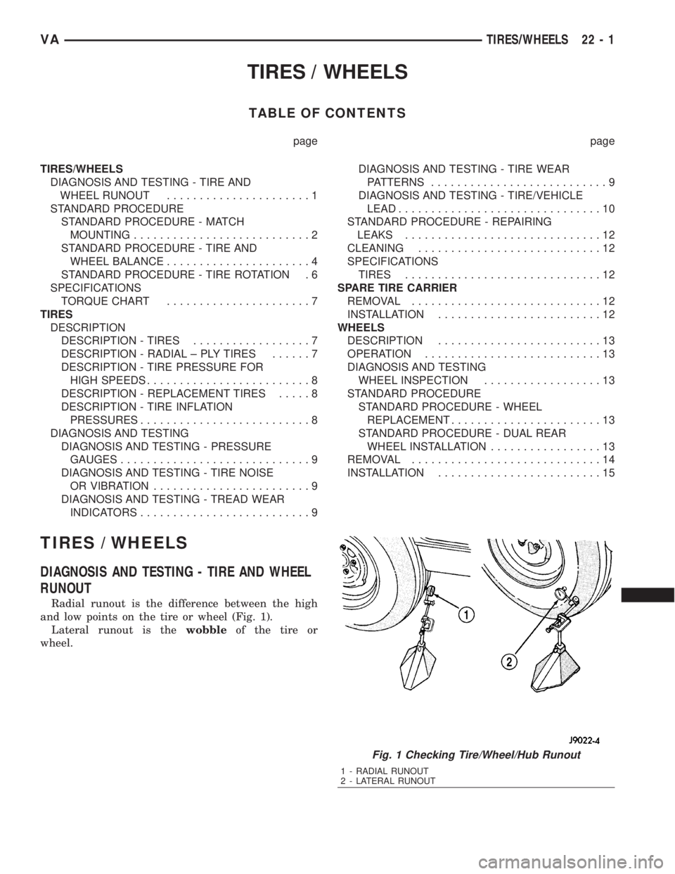
Radial runout is the difference between the high
and low points on the tire or wheel (Fig. 1).
Lateral runout is thewobbleof the tire or
wheel.
Fig. 1 Checking Tire/Wheel/Hub Runout
1 - RADIAL RUNOUT
2 - LATERAL RUNOUT
VATIRES/WHEELS 22 - 1
Page 1935 of 2305
Radial-ply tires must always be used in sets of
four. Under no circumstances should they be used on
the front only. They may be mixed with temporary
spare tires when necessary. A maximum speed of 50
MPH is recommended while a temporary spare is in
use.
Radial-ply tires have the same load-carrying capac-
ity as other types of tires of the same size. They also
use the same recommended inflation pressures.
The use of oversized tires, either in the front or
rear of the vehicle, can cause vehicle drive train fail-
ure. This could also cause inaccurate wheel speed
signals when the vehicle is equipped with Anti-Lock
Brakes.
The use of tires from different manufactures on the
same vehicle is NOT recommended. The proper tire
pressure should be maintained on all four tires.
DESCRIPTION - TIRE PRESSURE FOR HIGH
SPEEDS
Where speed limits allow the vehicle to be driven
at high speeds, correct tire inflation pressure is very
important. For speeds up to and including 120 km/h
(75 mph), tires must be inflated to the pressures
shown on the tire placard. For continuous speeds in
excess of 120 km/h (75 mph), tires must be inflated
to the maximum pressure specified on the tire side-
wall.
Vehicles loaded to the maximum capacity should
not be driven at continuous speeds above 75 mph
(120 km/h).
For emergency vehicles that are driven at speeds
over 90 mph (144 km/h), special high speed tires
must be used. Consult tire manufacturer for correct
inflation pressure recommendations.
DESCRIPTION - REPLACEMENT TIRES
The original equipment tires provide a proper bal-
ance of many characteristics such as:
²Ride
²Noise
²Handling
²Durability
²Tread life
²Traction
²Rolling resistance
²Speed capability
It is recommended that tires equivalent to the orig-
inal equipment tires be used when replacement is
needed.
Failure to use equivalent replacement tires may
adversely affect the safety and handling of the vehi-
cle.The use of oversize tires may cause interference
with vehicle components. Under extremes of suspen-
sion and steering travel, interference with vehicle
components may cause tire damage.
WARNING: FAILURE TO EQUIP THE VEHICLE WITH
TIRES HAVING ADEQUATE SPEED CAPABILITY
CAN RESULT IN SUDDEN TIRE FAILURE.
DESCRIPTION - TIRE INFLATION PRESSURES
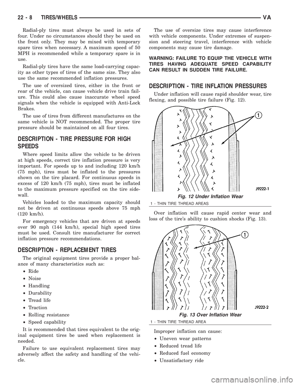
Under inflation will cause rapid shoulder wear, tire
flexing, and possible tire failure (Fig. 12).
Over inflation will cause rapid center wear and
loss of the tire's ability to cushion shocks (Fig. 13).
Improper inflation can cause:
²Uneven wear patterns
²Reduced tread life
²Reduced fuel economy
²Unsatisfactory ride
Fig. 12 Under Inflation Wear
1 - THIN TIRE THREAD AREAS
Fig. 13 Over Inflation Wear
1 - THIN TIRE THREAD AREA
22 - 8 TIRES/WHEELSVA
Page 1936 of 2305
²Vehicle drift
For proper tire pressure specification refer to the
Tire Inflation Pressure Chart provided with the vehi-
cles Owners Manual. A Certification Label on the
drivers side door pillar provides the minimum tire
and rim size for the vehicle. The label also list the
cold inflation pressure for these tires at full load
operation
Tire pressures have been chosen to provide safe
operation, vehicle stability, and a smooth ride. Tire
pressure should be checked cold once a month. Tire
pressure decreases as the ambient temperature
drops. Check tire pressure frequently when ambient
temperature varies widely.
Tire inflation pressures are cold inflation pressure.
The vehicle must sit for at least 3 hours to obtain the
correct cold inflation pressure reading. Or be driven
less than one mile after sitting for 3 hours. Tire
inflation pressures may increase from 2 to 6 pounds
per square inch (psi) during operation. Do not reduce
this normal pressure build-up.
WARNING: OVER OR UNDER INFLATED TIRES CAN
AFFECT VEHICLE HANDLING AND TREAD WEAR.
THIS MAY CAUSE THE TIRE TO FAIL SUDDENLY,
RESULTING IN LOSS OF VEHICLE CONTROL.
DIAGNOSIS AND TESTING
DIAGNOSIS AND TESTING - PRESSURE
GAUGES
A quality air pressure gauge is recommended to
check tire pressure. After checking the air pressure,
replace valve cap finger tight.
DIAGNOSIS AND TESTING - TIRE NOISE OR
VIBRATION
Radial-ply tires are sensitive to force impulses
caused by improper mounting, vibration, wheel
defects, or possibly tire imbalance.
To find out if tires are causing the noise or vibra-
tion, drive the vehicle over a smooth road at varying
speeds. Note the noise level during acceleration and
deceleration. The engine, differential and exhaust
noises will change as speed varies, while the tire
noise will usually remain constant.
DIAGNOSIS AND TESTING - TREAD WEAR
INDICATORS
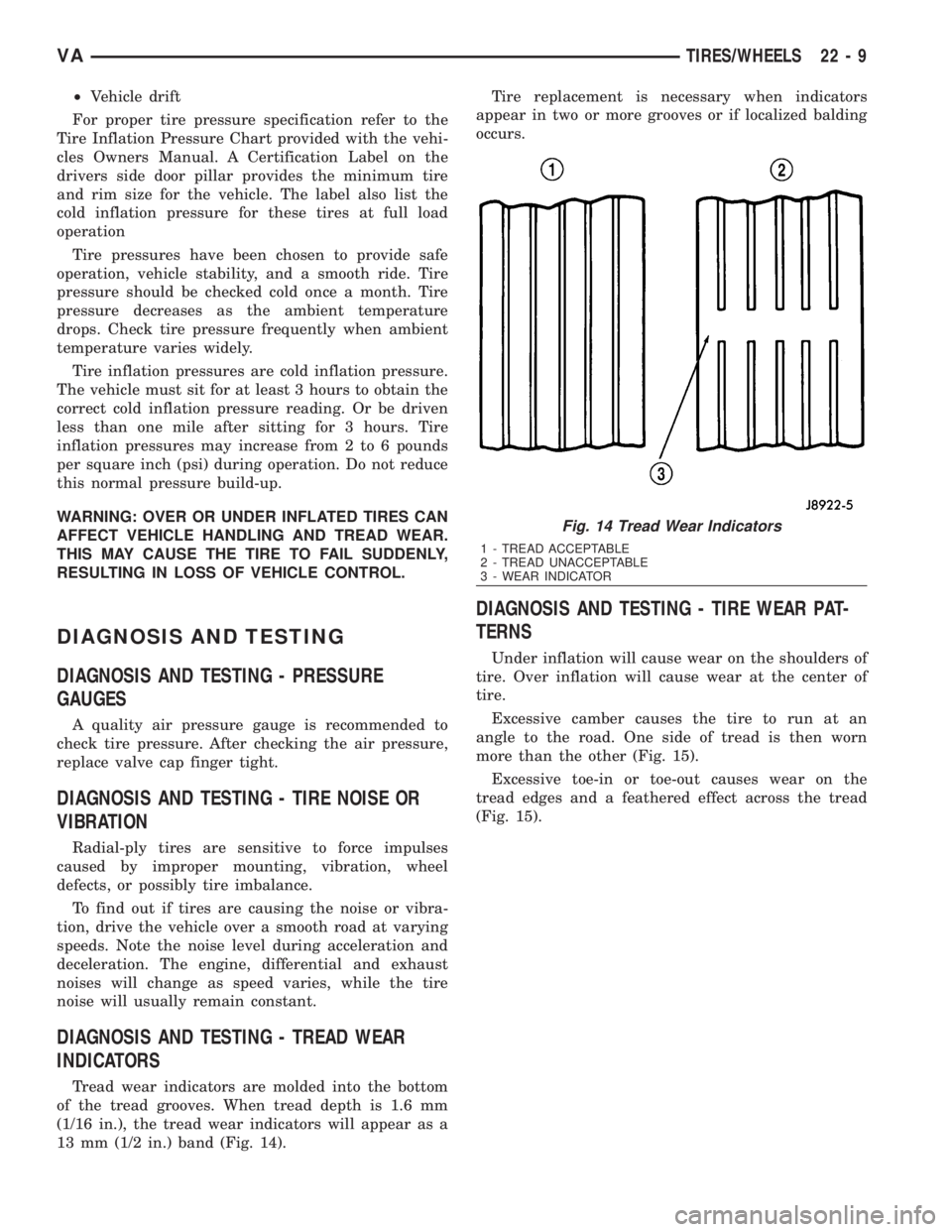
Tread wear indicators are molded into the bottom
of the tread grooves. When tread depth is 1.6 mm
(1/16 in.), the tread wear indicators will appear as a
13 mm (1/2 in.) band (Fig. 14).Tire replacement is necessary when indicators
appear in two or more grooves or if localized balding
occurs.
DIAGNOSIS AND TESTING - TIRE WEAR PAT-
TERNS
Under inflation will cause wear on the shoulders of
tire. Over inflation will cause wear at the center of
tire.
Excessive camber causes the tire to run at an
angle to the road. One side of tread is then worn
more than the other (Fig. 15).
Excessive toe-in or toe-out causes wear on the
tread edges and a feathered effect across the tread
(Fig. 15).
Fig. 14 Tread Wear Indicators
1 - TREAD ACCEPTABLE
2 - TREAD UNACCEPTABLE
3 - WEAR INDICATOR
VATIRES/WHEELS 22 - 9
Page 1981 of 2305
(2) Remove quarter trim panel. (Refer to 23 -
BODY/INTERIOR/QUARTER TRIM PANEL -
REMOVAL)
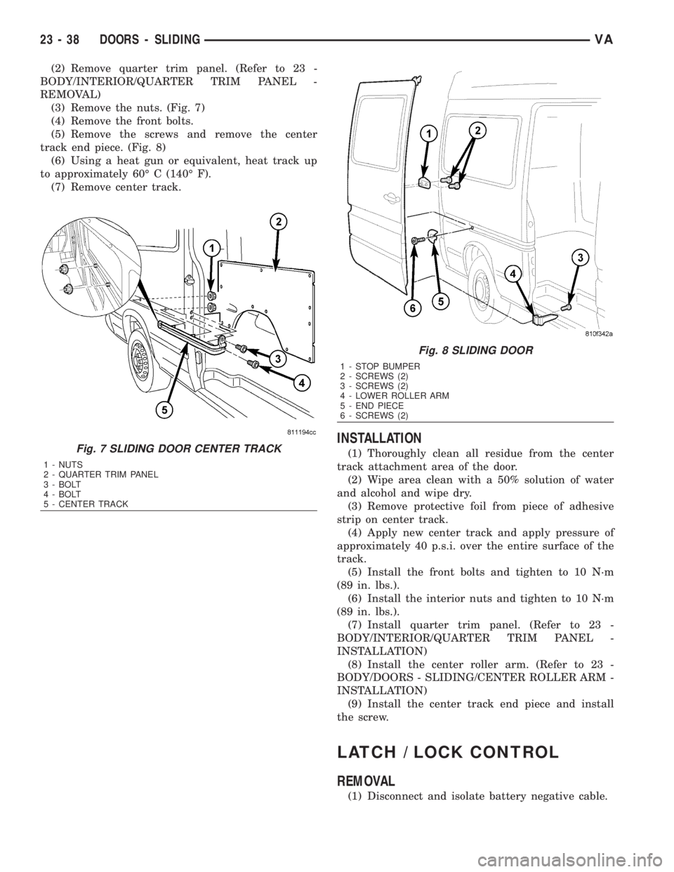
(3) Remove the nuts. (Fig. 7)
(4) Remove the front bolts.
(5) Remove the screws and remove the center
track end piece. (Fig. 8)
(6) Using a heat gun or equivalent, heat track up
to approximately 60É C (140É F).
(7) Remove center track.
INSTALLATION
(1) Thoroughly clean all residue from the center
track attachment area of the door.
(2) Wipe area clean with a 50% solution of water
and alcohol and wipe dry.
(3) Remove protective foil from piece of adhesive
strip on center track.
(4) Apply new center track and apply pressure of
approximately 40 p.s.i. over the entire surface of the
track.
(5) Install the front bolts and tighten to 10 N´m
(89 in. lbs.).
(6) Install the interior nuts and tighten to 10 N´m
(89 in. lbs.).
(7) Install quarter trim panel. (Refer to 23 -
BODY/INTERIOR/QUARTER TRIM PANEL -
INSTALLATION)
(8) Install the center roller arm. (Refer to 23 -
BODY/DOORS - SLIDING/CENTER ROLLER ARM -
INSTALLATION)
(9) Install the center track end piece and install
the screw.
LATCH / LOCK CONTROL
REMOVAL
(1) Disconnect and isolate battery negative cable.
Fig. 7 SLIDING DOOR CENTER TRACK
1 - NUTS
2 - QUARTER TRIM PANEL
3 - BOLT
4 - BOLT
5 - CENTER TRACK
Fig. 8 SLIDING DOOR
1 - STOP BUMPER
2 - SCREWS (2)
3 - SCREWS (2)
4 - LOWER ROLLER ARM
5 - END PIECE
6 - SCREWS (2)
23 - 38 DOORS - SLIDINGVA
Page 2098 of 2305
REAR REFRIGERANT RESERVOIR
REMOVAL.............................95
INSTALLATION.........................95
REAR SUCTION LINE
DESCRIPTION.........................96
REMOVAL.............................96
INSTALLATION.........................98
REFRIGERANT LINE COUPLER
DESCRIPTION.........................98OPERATION...........................98
REMOVAL.............................99
INSTALLATION.........................99
UNDERBODY LINES
REMOVAL............................100
INSTALLATION........................102
PLUMBING
DESCRIPTION
The refrigerant lines and hoses are used to carry
the refrigerant between the various air conditioning
system components. A barrier hose design with a
nylon tube, which is sandwiched between rubber lay-
ers, is used for the R-134a air conditioning system on
this vehicle. This nylon tube helps to further contain
the R-134a refrigerant, which has a smaller molecu-
lar structure than R-12 refrigerant. The ends of the
refrigerant hoses are made from lightweight alumi-
num or steel, and commonly use braze-less fittings.
Any kinks or sharp bends in the refrigerant plumb-
ing will reduce the capacity of the entire air condi-
tioning system. Kinks and sharp bends reduce the
flow of refrigerant in the system. A good rule for the
flexible hose refrigerant lines is to keep the radius of
all bends at least ten times the diameter of the hose.
In addition, the flexible hose refrigerant lines should
be routed so they are at least 80 millimeters (3
inches) from the exhaust manifold.
OPERATION
High pressures are produced in the refrigerant sys-
tem when the air conditioning compressor is operat-
ing. Extreme care must be exercised to make sure
that each of the refrigerant system connections is
pressure-tight and leak free. It is a good practice to
inspect all flexible hose refrigerant lines at least once
a year to make sure they are in good condition and
properly routed.
The refrigerant lines and hoses cannot be repaired
and, if faulty or damaged, they must be replaced.
WARNINGS
WARNING: The A/C system contains refrigerant
under high pressure. Repairs should only be per-
formed by qualified service personnel. Severe per-
sonal injury or death may result from improper
service procedures.
WARNING: Avoid breathing the refrigerant and
refrigerant oil vapor or mist. Exposure may irritate
the eyes, nose, and/or throat. Wear eye protectionwhen servicing the A/C refrigerant system. Serious
eye injury can result from direct contact with the
refrigerant. If eye contact occurs, seek medical
attention immediately.
WARNING: Do not expose the refrigerant to open
flame. Poisonous gas is created when refrigerant is
burned. An electronic leak detector is recom-
mended. Severe personal injury or death may result
from improper service procedures.
WARNING: If accidental system discharge occurs,
ventilate the work area before resuming service.
Large amounts of refrigerant released in a closed
work area will displace the oxygen and cause suf-
focation and death.
WARNING: The evaporation rate of R-134a refriger-
ant at average temperature and altitude is extremely
high. As a result, anything that comes in contact
with the refrigerant will freeze. Always protect the
skin or delicate objects from direct contact with the
refrigerant.
WARNING: The R-134a service equipment or the
vehicle refrigerant system should not be pressure
tested or leak tested with compressed air. Some
mixtures of air and R-134a have been shown to be
combustible at elevated pressures. These mixtures
are potentially dangerous, and may result in fire or
explosion causing property damage, personal injury
or death.
WARNING: The engine cooling system is designed
to develop internal pressures of 97 to 123 kilopas-
cals (14 to 18 pounds per square inch). Do not
remove or loosen the coolant pressure cap, cylin-
der block drain plugs, radiator drain, radiator
hoses, heater hoses, or hose clamps while the
engine cooling system is hot and under pressure.
Allow the vehicle to cool for a minimum of 15 min-
utes before opening the cooling system for service.
Failure to observe this warning can result in seri-
ous burns from the heated engine coolant.
VAPLUMBING 24 - 61
Page 2099 of 2305
CAUTIONS
CAUTION: Never add R-12 to a refrigerant system
designed to use R-134a. Do not use R-12 equipment
or parts on a R-134a A/C system. These refrigerants
are not compatible and damage to the A/C system
will result.
CAUTION: Never use R-12 refrigerant oil in a A/C
system designed to use R-134a refrigerant oil.
These refrigerant oils are not compatible and dam-
age to the A/C system will result.
CAUTION: The use of A/C system sealers may
result in damage to A/C refrigerant recovery/evacu-
ation/recharging equipment and/or A/C system.
Many federal, state/provincial and local regulations
prohibit the recharge of A/C systems with known
leaks. DaimlerChrysler recommends the detection
of A/C system leaks through the use of approved
leak detectors and fluorescent leak detection dyes.
Vehicles found with A/C system sealers should be
treated as contaminated and replacement of the
entire A/C refrigerant system is recommended. A/C
systems found to be contaminated with A/C system
sealers, A/C stop-leak products or seal conditioners
voids the warranty for the A/C system.
CAUTION: Recover the refrigerant before opening
any fitting or connection. Open the fittings with
caution, even after the system has been dis-
charged. Never open or loosen a connection before
recovering the refrigerant.
CAUTION: If equipped, do not remove the second-
ary retention clip from any spring-lock coupler con-
nection while the refrigerant system is under
pressure. Recover the refrigerant before removing
the secondary retention clip. Open the fittings with
caution, even after the system has been dis-
charged. Never open or loosen a connection before
recovering the refrigerant.
CAUTION: The internal parts of the A/C system will
remain stable as long as moisture-free refrigerant
and refrigerant oil is used. Abnormal amounts of
dirt, moisture or air can upset the chemical stability.
This may cause operational troubles or even seri-
ous damage if present in more than very small
quantities. Before disconnecting a component,
clean the outside of the fittings thoroughly to pre-
vent contamination from entering the refrigerant
system. Keep service tools and the work area clean.
Do not open the refrigerant system or uncap areplacement component until you are ready to ser-
vice the system. Immediately after disconnecting a
component from the refrigerant system, seal the
open fittings with a cap or plug. This will prevent
contamination from entering the A/C system.
CAUTION: Refrigerant oil will absorb moisture from
the atmosphere if left uncapped. Do not open a
container of refrigerant oil until you are ready to
use it. Replace the cap on the oil container immedi-
ately after using. Store refrigerant oil only in a
clean, airtight, and moisture-free container.
CAUTION: Do not overcharge the refrigerant sys-
tem. Overcharging will cause excessive compressor
head pressure and can cause compressor noise
and A/C system failure.
DIAGNOSIS AND TESTING
REFRIGERANT SYSTEM LEAKS
WARNING: R-134a service equipment or vehicle A/C
system should not be pressure tested or leak tested
with compressed air. Mixture of air and R-134a can
be combustible at elevated pressures. These mix-
tures are potentially dangerous and may result in
fire or explosion causing property damage, per-
sonal injury or death.
Avoid breathing A/C refrigerant and lubricant vapor
or mist. Exposure may irritate eyes, nose and
throat. Use only approved service equipment meet-
ing SAE requirements to discharge R-134a system.
If accidental system discharge occurs, ventilate
work area before resuming service.
If the A/C system is not cooling properly, determine
if the refrigerant system is fully charged with
R-134a. This is accomplished by performing a Refrig-
erant System Charge Level test (Refer to 24 - HEAT-
ING & AIR CONDITIONING/PLUMBING -
DIAGNOSIS AND TESTING - REFRIGERANT SYS-
TEM CHARGE LEVEL) or by completely evacuating
and recharging the A/C system. If the A/C liquid line
pressure is found to be less than 345 kPa (50 psi)
while performing the Refrigerant System Charge
Level test, proceed to the System Empty procedure
below. If liquid line pressure is found to be greater
than 345 kPa (50 psi), proceed to the System Low
procedure. If the refrigerant system is empty or low
in refrigerant charge, a leak at any line fitting or
component seal is likely. A review of the fittings,
lines and components for oily residue is an indication
of the leak location. To detect a leak in the refriger-
ant system, perform one of the following procedures
as indicated by the symptoms.
24 - 62 PLUMBINGVA
Page 2159 of 2305
INSIDE HANDLE ACTUATOR......23-33, 23-36
INSTRUMENT CLUSTER................8J-2
INSTRUMENT PANEL ANTENNA CABLE....8A-2
INSTRUMENT PANEL ASSEMBLY........23-59
INSTRUMENT PANEL CENTER BEZEL.....23-57
INSTRUMENT PANEL DUCTS...........24-51
INTAKE AIR PRESSURE SENSOR........14-43
INTAKE AIR TEMPERATURE SENSOR.....14-42
INTAKE MANIFOLD....................9-65
INTERIOR..........................23-70
INTERMEDIATE SHAFT.................19-4
INTERNATIONAL SYMBOLS...............0-9
INTERNATIONAL SYMBOLS...........Intro.-2
INTRUSION SENSOR...................8Q-1
IN - CAR TEMPERATURE SENSOR.......24-21
JUMP STARTING.......................0-6
KEY / LOCK CYLINDER.................19-5
KNUCKLE.............................2-5
LAMPS / LIGHTING - EXTERIOR..........8L-2
LAMPS / LIGHTING - INTERIOR.........8L-28
LATCH RELEASE CABLE...............23-52
LATCH RELEASE HANDLE..............23-52
LATCH STRIKER.....................23-18
LATCH ..................23-18, 23-33, 23-52
LATCH / LOCK CONTROL...............23-38
LATERAL ACCELERATION SENSOR........5-33
LEFT MOUNT.........................9-55
LEVER..............................5-26
LICENSE PLATE BRACKET..............23-48
LICENSE PLATE LAMP BULB...........8L-19
LICENSE PLATE LAMP UNIT............8L-19
LINKAGE............................19-9
LIQUID LINE........................24-77
LOCK CYLINDER.....................23-18
LOW BEAM HEADLAMP BULB..........8L-20
LOW FUEL INDICATOR................8J-19
LOW OIL LEVEL INDICATOR............8J-20
LOWER BALL JOINT....................2-6
LOWER CONTROL ARM.................2-6
LOWER ROLLER ARM.................23-37
MAINTENANCE INDICATOR.............8J-20
MAINTENANCE SCHEDULES..............0-8
MALFUNCTION INDICATOR LAMP (MIL) . . . 8J-21
MANIFOLD AIR FLOW (MAF) SENSOR....14-44
MASTER CYLINDER...................5-17
MASTER LOCK SWITCH................8N-1
METRIC SYSTEM...................Intro.-6
MODE DOOR CABLES.................24-21
MULTI - FUNCTION INDICATOR..........8J-22
MULTI - FUNCTION SWITCH............8L-21
O2 SENSOR.........................14-45
ODOMETER.........................8J-22
OIL COOLER & LINES..................9-56
OIL FILTER ..........................9-57
OIL JET .............................9-57
OIL PAN .............................9-58
OIL PUMP...........................9-61
OIL PUMP.........................21-154
OIL SENSOR.........................9-64
OIL ................................9-56
OPENING DIMENSIONS................23-93
OUTPUT SHAFT BEARING.............21-156
OUTPUT SHAFT SEAL................21-159
PAINT TOUCH - UP...................23-77
PAINT.............................23-77
PARK BRAKE INDICATOR..............8J-23
PARK BRAKE SWITCH.................8L-21
PARK LOCK CABLE..................21-160
PARKING BRAKE......................5-23
PASSENGER AIRBAG BRACKET.........8O-27
PASSENGER AIRBAG.................8O-24
PASSENGER HEATED SEAT SWITCH.....8G-13
PEDAL..............................5-19
PISTON & CONNECTING ROD............9-45
PISTON RINGS.......................9-52
PISTONS..........................21-163
PLANETARY GEARTRAIN..............21-164
PLUMBING.........................24-61
POWER BRAKE BOOSTER...............5-19
POWER DISTRIBUTION CENTER.......8W-97-3
POWER DISTRIBUTION..............8W-97-1
POWER MIRROR SWITCH..............8N-3
POWER MIRRORS....................8N-3
POWER OUTLET
...................8W-97-3
POWER WINDOW SWITCH
..............8N-5
POWER WINDOWS
....................8N-5
PROP ROD
.........................23-53
PROPELLER SHAFT
.................3-1, 3-7PUMP.............................19-11
QUARTER TRIM PANEL................23-74
QUARTER WINDOW..................23-84
RADIATOR CROSSMEMBER............23-49
RADIATOR FAN.......................7-14
RADIATOR PRESSURE CAP..............7-19
RADIATOR...........................7-17
RADIO..............................8A-2
RAIN SENSOR CONTROL MODULE......8R-15
RAIN SENSOR.......................8R-12
REAR AXLE..........................3-12
REAR A / C CONDENSER FAN...........24-83
REAR A / C EVAPORATOR..............24-84
REAR A / C EXPANSION VALVE..........24-85
REAR BUMPER - STEP.................13-2
REAR CROSSMEMBER - TRANSMISSION . . 13-11
REAR DISCHARGE LINE...............24-88
REAR FASCIA........................13-3
REAR LATCH STRIKER................23-40
REAR LATCH........................23-40
REAR LIQUID LINE...................24-91
REAR RECEIVER / DRIER..............24-94
REAR REFRIGERANT RESERVOIR........24-95
REAR SEAT BACK SHIELD..............23-82
REAR SEAT BELT & RETRACTOR........8O-28
REAR SEAT BELT BUCKLE.............8O-30
REAR SIDE MARKER LAMP BULB.......8L-22
REAR SUCTION LINE..................24-96
REAR TURN LAMP BULB..............8L-23
REAR VIEW MIRROR.................23-75
REAR WHEEL SPEED SENSOR...........5-31
REAR WINDOW DEFOGGER GRID........8G-7
REAR WINDOW DEFOGGER RELAY.......8G-3
REAR WINDOW DEFOGGER SWITCH......8G-4
REAR...............................2-11
RECEIVER / DRIER...................24-79
RECIRCULATION DOOR ACTUATOR......24-22
REFRIGERANT LINE COUPLER..........24-98
REFRIGERANT OIL...................24-81
REFRIGERANT.......................24-80
RELAY...........................8W-97-4
REMOTE KEYLESS ENTRY
TRANSMITTER.......................8N-1
REPEATER LAMP BULB................8L-23
REPEATER LAMP UNIT................8L-24
RESTRAINTS.........................8O-2
RIGHT MOUNT.......................9-56
ROTORS............................5-20
SAFETY LATCH......................23-53
SEAL - PINION........................3-39
SEAT ADJUSTERS - FRONT.............23-81
SEAT BACK CUSHION / COVER - REAR....23-82
SEAT BACK - FRONT..................23-80
SEAT BELT SWITCH..................8O-31
SEAT BELT TENSIONER................8O-32
SEAT BELT TURNING LOOP ADJUSTER . . . 8O-33
SEAT CUSHION - FRONT...............23-80
SEAT CUSHION / COVER - REAR.........23-83
SEATBELT INDICATOR.................8J-24
SEAT - FRONT.......................23-79
SEAT - REAR........................23-81
SECURITY SYSTEM MODULE............8Q-2
SENTRY KEY REMOTE ENTRY MODULE....8Q-2
SERVO..............................8P-2
SHAFT - AXLE DUAL REAR WHEELS......3-27
SHAFT - AXLE SINGLE REAR WHEEL......3-23
SHIFT MECHANISM..................21-168
SHOCK..............................2-13
SHOES..............................5-27
SIDE CURTAIN AIRBAG................8O-35
SIDE IMPACT SENSOR................8O-39
SIDE VIEW MIRROR..................23-49
SIDE VIEW MIRROR - GLASS...........23-50
SIREN..............................8Q-4
SLIDING DOOR......................23-40
SOLENOID.........................21-171
SPARE TIRE CARRIER.................22-12
SPEAKER............................8A-2
SPEED CONTROL.....................8P-1
SPEEDOMETER......................8J-25
SPRING CLAMP PLATES.................2-8
SPRING SHACKLE.....................2-15
SPRING STOP PLATES..................2-9
SPRING
.........................2-7, 2-14
STABILIZER BAR
..................2-9, 2-15
STABILIZER LINK
.................2-10, 2-16
STABILIZER
.........................23-45
STARTER MOTOR RELAY
..............8F-35STARTER MOTOR....................8F-33
STARTING SYSTEM...................8F-28
STEERING ANGLE SENSOR..............5-32
STEERING COLUMN OPENING COVER....23-68
STEERING WHEEL.....................19-6
STEERING...........................19-1
STEPWELL SCUFF PADS...............23-75
STRUT..............................2-10
SUCTION LINE.......................24-81
SUN VISOR.........................23-76
SUPPORT PLATE......................5-23
SUPPRESSOR FILTER - REAR BLOWER
MOTOR............................24-41
SUPPRESSOR FILTER - REAR
CONDENSER FAN....................24-43
SWITCH.............................8P-3
TACHOMETER.......................8J-25
TAIL LAMP UNIT.....................8L-25
TAILPIPE............................11-3
TEMPERATURE CONTROL..............24-38
TEMPERATURE SENSOR...............24-40
TEMPERATURE SENSOR / PARK -
NEUTRAL CONTACT..................21-176
TERMINAL........................Intro.-10
THREADED HOLE REPAIR.............Intro.-6
TIE ROD END ........................19-10
TIME DELAY RELAY....................8L-35
TIMING CHAIN AND SPROCKETS.........9-72
TIMING CHAIN COVER.................9-70
TIMING CHAIN TENSIONER..............9-81
TIRES..............................22-7
TIRES / WHEELS......................22-1
TONE WHEEL........................5-32
TOP COVER.........................23-67
TOP COVER - CLUSTER................23-64
TOP COVER - TRAY...................23-65
TORQUE CONVERTER HUB SEAL.......21-184
TORQUE CONVERTER................21-178
TORQUE REFERENCES...............Intro.-9
TOWING.............................0-7
TRACTION CONTROL INDICATOR........8J-26
TRACTION CONTROL MALFUNCTION
INDICATOR.........................8J-27
TRAILER HITCH......................13-11
TRANSMISSION CONTROL MODULE......8E-6
TRANSPONDER KEY...................8Q-5
TRIM PANEL.............23-18, 23-34, 23-46
TURBOCHARGER SYSTEM..............11-3
TURBOCHARGER......................11-6
TURN SIGNAL INDICATOR..............8J-27
TURN SIGNAL RELAY.................8L-26
UNDERBODY LINES..................24-100
UPPER ROLLER ARM.................23-36
VACUUM PUMP.......................9-54
VALVE COOLER.......................25-6
VALVE SPRINGS......................9-35
VALVE STEM SEALS...................9-34
VALVE ..............................25-5
VEHICLE IDENTIFICATION NUMBER.....Intro.-1
VEHICLE THEFT SECURITY..............8Q-1
VIBRATION DAMPER...................9-53
VOLTAGE REGULATOR.................8F-24
WAIT - TO - START INDICATOR..........8J-28
WASHER FLUID INDICATOR............8J-29
WASHER FLUID LEVEL SWITCH.........8R-16
WASHER HOSES / TUBES..............8R-18
WASHER NOZZLE....................8R-18
WASHER PUMP / MOTOR..............8R-19
WASHER RESERVOIR.................8R-21
WATER IN FUEL SENSOR..............14-30
WATER PUMP........................7-20
WATER VALVE .......................24-83
WATER - IN - FUEL INDICATOR..........8J-29
WHEEL ALIGNMENT...................2-17
WHEELS...........................22-13
WINDOW MOTOR.....................8N-5
WINDOW REGULATOR - MANUAL........23-21
WINDOW REGULATOR - POWER........23-20
WINDSHIELD........................23-85
WIPER ARM........................8R-23
WIPER BLADE.......................8R-26
WIPER LINKAGE.....................8R-28
WIPER MOTOR......................8R-31
WIPER RELAY.......................8R-34
WIPERS/WASHERS....................8R-2
WIRING DIAGRAM INFORMATION......Intro.-1
YAW RATE SENSOR...................5-35
2 INDEXVA
Description Group-Page Description Group-Page Description Group-Page
Page 2166 of 2305
1.0 INTRODUCTION
The procedures contained in this manual include
all of the specifications, instructions, and graphics
needed to diagnose NAG1 Electronic Automatic
Transmission and Shift Lever Assembly problems.
The diagnostics in this manual are based on the
failure condition or symptom being present at the
time of diagnosis.
When repairs are required, refer to the appropri-
ate volume of the service information for the proper
removal and repair procedure.
READ THIS MANUAL BEFORE TRYING TO
DIAGNOSE A VEHICLE TROUBLE CODE.
Diagnostic procedures change every year. New
diagnostic systems may be added and/or carryover
systems may be enhanced. It is recommended that
you review the entire manual to become familiar
with all new and changed diagnostic procedures.
1.1 SYSTEM COVERAGE
This diagnostic procedures manual covers all
Sprinter (VA) equipped with a NAG1 Automatic
Transmission.
1.2 SIX -STEP TROUBLESHOOTING
PROCEDURE
Diagnosis of the NAG1 electronic transmission is
done in six basic steps:
Verification of complaint
Verification of any related symptoms
Symptom analysis
Problem isolation
Repair of isolated problem
Verification of proper operation
2.0 IDENTIFICATION OF
SYSTEM
The NAG1 Transmission family can be identified
by the presence of a 13 pin electrical connector, with
a bayonet lock on the right hand side of the trans-
mission. The connector is oriented horizontally.
3.0 SYSTEM DESCRIPTION AND
FUNCTIONAL OPERATION
3.1 GENERAL DESCRIPTION
The NAG1 electronic transmission is an electron-
ically controlled five speed transmission with a
controlled slip torque converter. The NAG1 elec-tronic transmission is a conventional transmission
in that it uses hydraulically applied clutches to shift
a planetary gear train. However, the electronic
control system replaces many of the mechanical and
hydraulic components used in conventional trans-
mission valve bodies.
The ratios for the gear stages are obtained by 3
planetary gear sets. Fifth Gear is designed as an
Overdrive with a high speed ratio. The gears are
actuated electronically/hydraulically. The electronic
control system enables precise adaptation of pres-
sures to the respective operating conditions and to
the engine output during a shift phase, which
results in a significant improvement in shift qual-
ity.
3.2 FUNCTIONAL OPERATION
The NAG1 electronic transmission has a fully
adaptive control system. The system performs its
functions based on continuous real-time sensor and
switch feedback information. In addition the TCM
receives information from the Shift Lever Assembly,
ECM (engine management) and ABS (chassis sys-
tems) controllers over the CAN bus. The CAN bus is
a high speed communication bus that allows real
time control capability between various controllers.
Most messages are sent every 20 milliseconds, this
means critical information can be shared between
the Transmission, Shifter, Engine and ABS control-
lers. The CAN bus is a two wire bus with aCAN C
Bus (+) circuitand aCAN C Bus (-) circuit. The
CAN bus uses a twisted pair of wires in the harness
to reduce the potential of radio and noise interfer-
ence. The CAN bus also uses a 120 ohm terminating
resistor in both the ECM and Sentry Key Remote
Entry Module (SKREEM) modules. The module
terminating resistance is measured across both
CAN bus circuits at the ECM or SKREEM module.
The control system automatically adapts to
changes in engine performance, vehicle speed, and
transmission temperature variations to provide
consistent shift quality. The control system ensures
that clutch operation during upshifting and down-
shifting is more responsive without increased
harshness. The TCM controls the actuation of sole-
noid valves for modulating shift pressure and gear
change. The required pressure level is calculated
from the load condition, engine speed. Power for the
transmission system is supplied through the Trans-
mission Relay. The TCM is located in the under the
drivers seat of the vehicle.
The Transmission Control Module (TCM) contin-
uously checks for electrical problems, mechanical
problems, and some hydraulic problems. When a
problem is sensed, the TCM stores a diagnostic
trouble code (DTC). Some of these codes cause the
transmission to go into9limp-in9or9default9mode.
1
GENERAL INFORMATION
Page 2170 of 2305
Emergency running function
If DTCs occur, safe-driving conditions must be re-
tained but full functionality of the transmission will
be limited to avoid damaging the automatic trans-
mission. In the event of certain DTCs the TCM
switches to emergency running. The TCM will store
the appropriate DTC codes and solenoids will be
de-energized (turned off)
The transmission effects will be:
²The last gear shifted remains in that position
²The modulating pressure and shift pressure in-
crease to maximum value
²The torque converter clutch is disengaged
(turned off)
Shifting manually after a DTC detection
NOTE: The vehicle can still be shifted
manually to 2nd or reverse gear.
To accomplish these shifts you must
Stop the vehicle
Turn the ignition off
Start the engine
Place the selector lever into D for 2nd gear
Place the selector lever into R for reverse gear
The emergency running function is retained until
the DTC is eliminated or the stored DTC code is
erased.
Stored (Intermittent) DTCs can be reset by cy-
cling the ignition switch
3.3.3 TROUBLE CODE ERASURE
Diagnostic Trouble Codes can be erased in two
ways. The first is to erase the DTC with the DRBIII
or scan tool. The second is if the DTC is no longer
present, the DTC is reset by the TCM (after an
ignition cycle), which will place the DTC in an
intermittent status (Stored DTC).
When there are no diagnostic trouble codes
stored in memory, the DRBIIItwill display
(NO DTC's DETECTED(
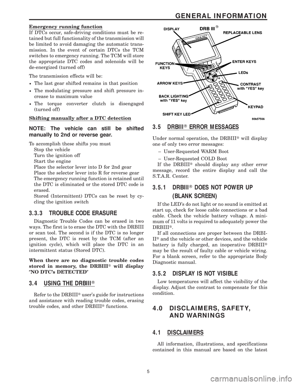
3.4 USING THE DRBIIIT
Refer to the DRBIIItuser's guide for instructions
and assistance with reading trouble codes, erasing
trouble codes, and other DRBIIItfunctions.
3.5 DRBIIITERROR MESSAGES
Under normal operation, the DRBIIItwill display
one of only two error messages:
± User-Requested WARM Boot
± User-Requested COLD Boot
If the DRBIIItshould display any other error
message, record the entire display and call the
S.T.A.R. Center.
3.5.1 DRBIIITDOES NOT POWER UP
(BLANK SCREEN)
If the LED's do not light or no sound is emitted at
start up, check for loose cable connections or a bad
cable. Check the vehicle battery voltage. A mini-
mum of 11 volts is required to adequately power the
DRBIIIt.
If all connections are proper between the DRBI-
IItand the vehicle or other devices, and the vehicle
battery is fully charged, an inoperative DRBIIIt
may be the result of faulty cable or vehicle wiring.
For a blank screen, refer to the appropriate Body
Diagnostic manual.
3.5.2 DISPLAY IS NOT VISIBLE
Low temperatures will affect the visibility of the
display. Adjust the contrast to compensate for this
condition.
4.0 DISCLAIMERS, SAFETY,
AND WARNINGS
4.1 DISCLAIMERS
All information, illustrations, and specifications
contained in this manual are based on the latest
5
GENERAL INFORMATION