fuse diagram MERCEDES-BENZ SPRINTER 2006 Service Manual
[x] Cancel search | Manufacturer: MERCEDES-BENZ, Model Year: 2006, Model line: SPRINTER, Model: MERCEDES-BENZ SPRINTER 2006Pages: 2305, PDF Size: 48.12 MB
Page 12 of 2305
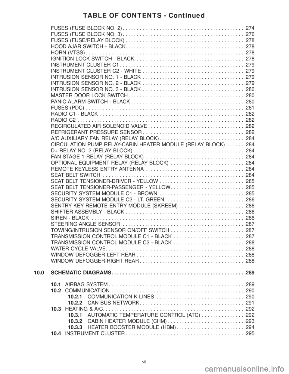
TABLE OF CONTENTS - Continued
FUSES (FUSE BLOCK NO. 2)............................................274
FUSES (FUSE BLOCK NO. 3)............................................276
FUSES (FUSE/RELAY BLOCK)...........................................278
HOOD AJAR SWITCH - BLACK...........................................278
HORN (VTSS).........................................................278
IGNITION LOCK SWITCH - BLACK........................................278
INSTRUMENT CLUSTER C1.............................................279
INSTRUMENT CLUSTER C2 - WHITE.....................................279
INTRUSION SENSOR NO. 1 - BLACK.....................................279
INTRUSION SENSOR NO. 2 - BLACK.....................................279
INTRUSION SENSOR NO. 3 - BLACK.....................................280
MASTER DOOR LOCK SWITCH..........................................280
PANIC ALARM SWITCH - BLACK.........................................280
FUSES (PDC).........................................................281
RADIO C1 - BLACK....................................................282
RADIO C2............................................................282
RECIRCULATED AIR SOLENOID VALVE...................................282
REFRIGERANT PRESSURE SENSOR.....................................282
A/C AUXILIARY FAN RELAY (RELAY BLOCK)...............................284
CIRCULATION PUMP RELAY-CABIN HEATER MODULE (RELAY BLOCK).......284
D+ RELAY NO. 2 (RELAY BLOCK)........................................284
FAN STAGE 1 RELAY (RELAY BLOCK)....................................284
OPTIONAL EQUIPMENT RELAY (RELAY BLOCK)...........................284
REMOTE KEYLESS ENTRY ANTENNA....................................284
SEAT BELT SWITCH...................................................284
SEAT BELT TENSIONER-DRIVER - YELLOW...............................285
SEAT BELT TENSIONER-PASSENGER - YELLOW...........................285
SECURITY SYSTEM MODULE C1 - BROWN...............................285
SECURITY SYSTEM MODULE C2 - LT. GREEN.............................286
SENTRY KEY REMOTE ENTRY MODULE (SKREEM)........................286
SHIFTER ASSEMBLY - BLACK...........................................286
SIREN - BLACK.......................................................286
STEERING ANGLE SENSOR............................................287
TOWING/INTRUSION SENSOR ON/OFF SWITCH...........................287
TRANSMISSION CONTROL MODULE C1 - BLACK..........................287
TRANSMISSION CONTROL MODULE C2 - BLACK..........................288
WATER CYCLE VALVE..................................................288
WINDOW DEFOGGER-LEFT REAR.......................................288
WINDOW DEFOGGER-RIGHT REAR......................................288
10.0 SCHEMATIC DIAGRAMS................................................289
10.1AIRBAG SYSTEM.................................................289
10.2COMMUNICATION................................................290
10.2.1COMMUNICATION K-LINES................................290
10.2.2CAN BUS NETWORK......................................291
10.3HEATING & A/C...................................................292
10.3.1AUTOMATIC TEMPERATURE CONTROL (ATC)................292
10.3.2CABIN HEATER MODULE (CHM)............................293
10.3.3HEATER BOOSTER MODULE (HBM).........................294
10.4INSTRUMENT CLUSTER...........................................295
vii
Page 159 of 2305
Symptom:
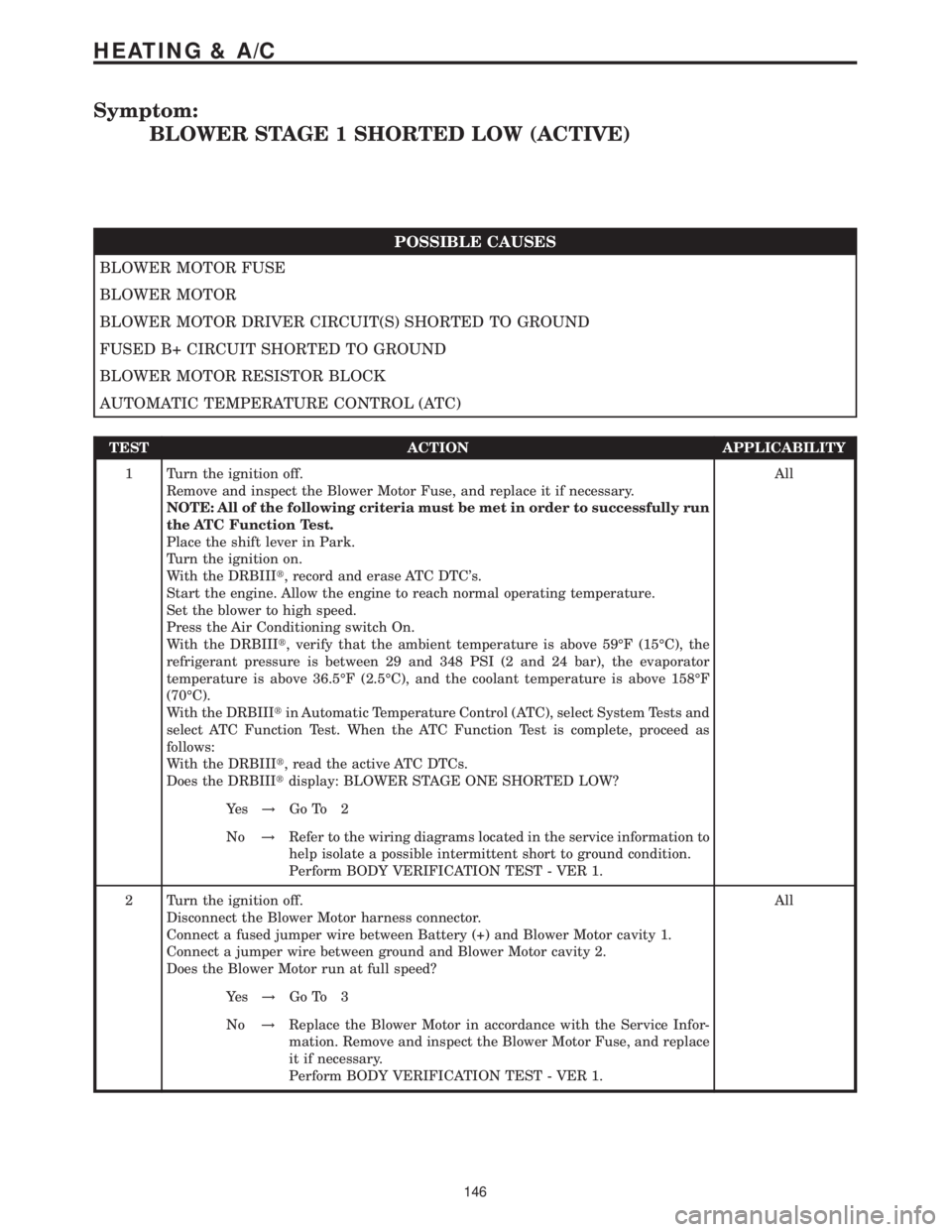
BLOWER STAGE 1 SHORTED LOW (ACTIVE)
POSSIBLE CAUSES
BLOWER MOTOR FUSE
BLOWER MOTOR
BLOWER MOTOR DRIVER CIRCUIT(S) SHORTED TO GROUND
FUSED B+ CIRCUIT SHORTED TO GROUND
BLOWER MOTOR RESISTOR BLOCK
AUTOMATIC TEMPERATURE CONTROL (ATC)
TEST ACTION APPLICABILITY
1 Turn the ignition off.
Remove and inspect the Blower Motor Fuse, and replace it if necessary.
NOTE: All of the following criteria must be met in order to successfully run
the ATC Function Test.
Place the shift lever in Park.
Turn the ignition on.
With the DRBIIIt, record and erase ATC DTC's.
Start the engine. Allow the engine to reach normal operating temperature.
Set the blower to high speed.
Press the Air Conditioning switch On.
With the DRBIIIt, verify that the ambient temperature is above 59ÉF (15ÉC), the
refrigerant pressure is between 29 and 348 PSI (2 and 24 bar), the evaporator
temperature is above 36.5ÉF (2.5ÉC), and the coolant temperature is above 158ÉF
(70ÉC).
With the DRBIIItin Automatic Temperature Control (ATC), select System Tests and
select ATC Function Test. When the ATC Function Test is complete, proceed as
follows:
With the DRBIIIt, read the active ATC DTCs.
Does the DRBIIItdisplay: BLOWER STAGE ONE SHORTED LOW?All
Ye s!Go To 2
No!Refer to the wiring diagrams located in the service information to
help isolate a possible intermittent short to ground condition.
Perform BODY VERIFICATION TEST - VER 1.
2 Turn the ignition off.
Disconnect the Blower Motor harness connector.
Connect a fused jumper wire between Battery (+) and Blower Motor cavity 1.
Connect a jumper wire between ground and Blower Motor cavity 2.
Does the Blower Motor run at full speed?All
Ye s!Go To 3
No!Replace the Blower Motor in accordance with the Service Infor-
mation. Remove and inspect the Blower Motor Fuse, and replace
it if necessary.
Perform BODY VERIFICATION TEST - VER 1.
146
HEATING & A/C
Page 233 of 2305
Symptom:
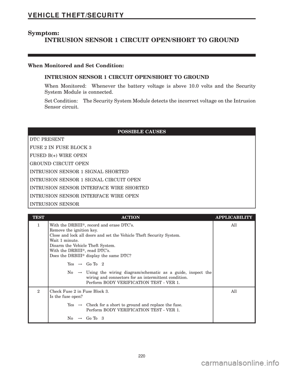
INTRUSION SENSOR 1 CIRCUIT OPEN/SHORT TO GROUND
When Monitored and Set Condition:
INTRUSION SENSOR 1 CIRCUIT OPEN/SHORT TO GROUND
When Monitored: Whenever the battery voltage is above 10.0 volts and the Security
System Module is connected.
Set Condition: The Security System Module detects the incorrect voltage on the Intrusion
Sensor circuit.
POSSIBLE CAUSES
DTC PRESENT
FUSE 2 IN FUSE BLOCK 3
FUSED B(+) WIRE OPEN
GROUND CIRCUIT OPEN
INTRUSION SENSOR 1 SIGNAL SHORTED
INTRUSION SENSOR 1 SIGNAL CIRCUIT OPEN
INTRUSION SENSOR INTERFACE WIRE SHORTED
INTRUSION SENSOR INTERFACE WIRE OPEN
INTRUSION SENSOR
TEST ACTION APPLICABILITY
1 With the DRBIIIt, record and erase DTC's.
Remove the ignition key.
Close and lock all doors and set the Vehicle Theft Security System.
Wait 1 minute.
Disarm the Vehicle Theft System.
With the DRBIIIt, read DTC's.
Does the DRBIIItdisplay the same DTC?All
Ye s!Go To 2
No!Using the wiring diagram/schematic as a guide, inspect the
wiring and connectors for an intermittent condition.
Perform BODY VERIFICATION TEST - VER 1.
2 Check Fuse 2 in Fuse Block 3.
Is the fuse open?All
Ye s!Check for a short to ground and replace the fuse.
Perform BODY VERIFICATION TEST - VER 1.
No!Go To 3
220
VEHICLE THEFT/SECURITY
Page 236 of 2305
Symptom:
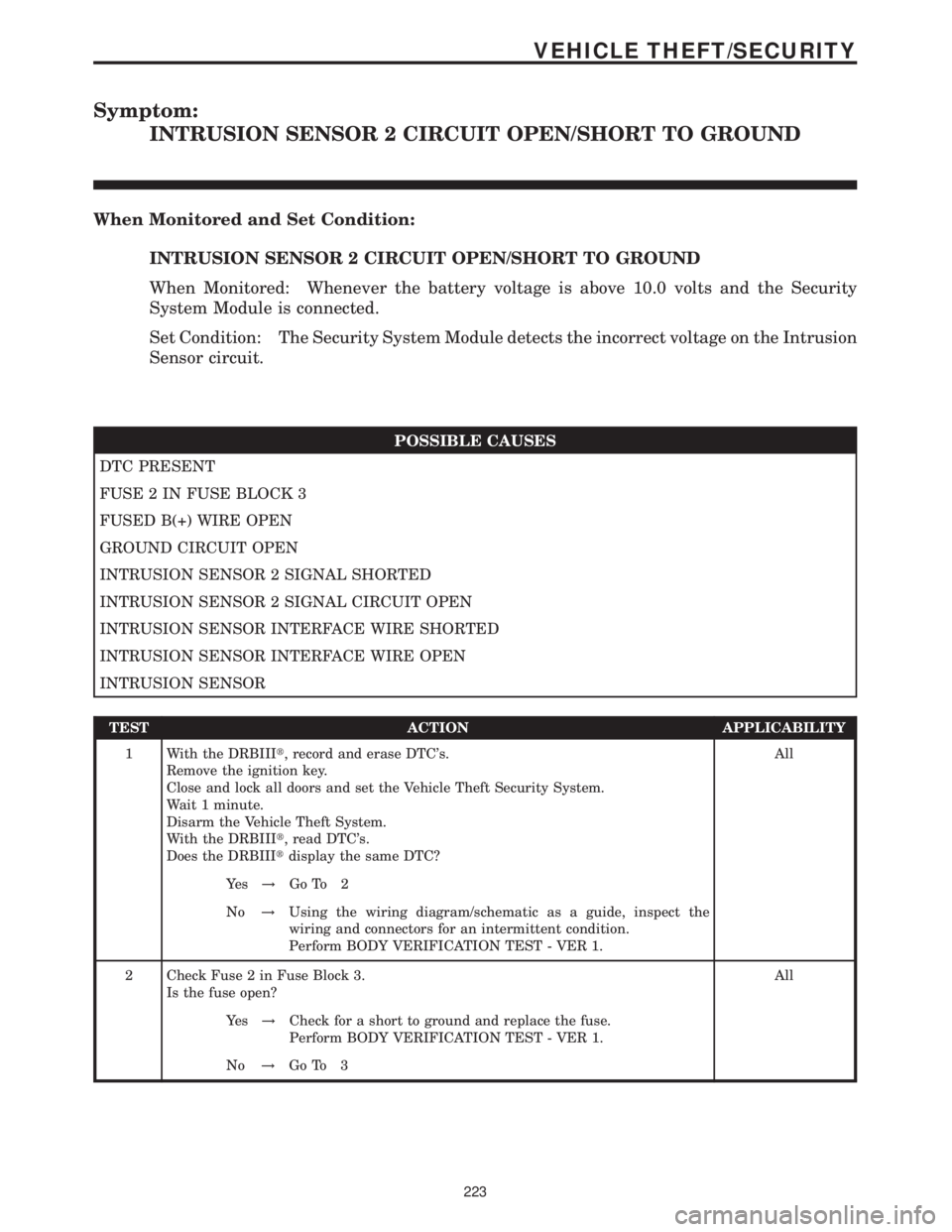
INTRUSION SENSOR 2 CIRCUIT OPEN/SHORT TO GROUND
When Monitored and Set Condition:
INTRUSION SENSOR 2 CIRCUIT OPEN/SHORT TO GROUND
When Monitored: Whenever the battery voltage is above 10.0 volts and the Security
System Module is connected.
Set Condition: The Security System Module detects the incorrect voltage on the Intrusion
Sensor circuit.
POSSIBLE CAUSES
DTC PRESENT
FUSE 2 IN FUSE BLOCK 3
FUSED B(+) WIRE OPEN
GROUND CIRCUIT OPEN
INTRUSION SENSOR 2 SIGNAL SHORTED
INTRUSION SENSOR 2 SIGNAL CIRCUIT OPEN
INTRUSION SENSOR INTERFACE WIRE SHORTED
INTRUSION SENSOR INTERFACE WIRE OPEN
INTRUSION SENSOR
TEST ACTION APPLICABILITY
1 With the DRBIIIt, record and erase DTC's.
Remove the ignition key.
Close and lock all doors and set the Vehicle Theft Security System.
Wait 1 minute.
Disarm the Vehicle Theft System.
With the DRBIIIt, read DTC's.
Does the DRBIIItdisplay the same DTC?All
Ye s!Go To 2
No!Using the wiring diagram/schematic as a guide, inspect the
wiring and connectors for an intermittent condition.
Perform BODY VERIFICATION TEST - VER 1.
2 Check Fuse 2 in Fuse Block 3.
Is the fuse open?All
Ye s!Check for a short to ground and replace the fuse.
Perform BODY VERIFICATION TEST - VER 1.
No!Go To 3
223
VEHICLE THEFT/SECURITY
Page 239 of 2305
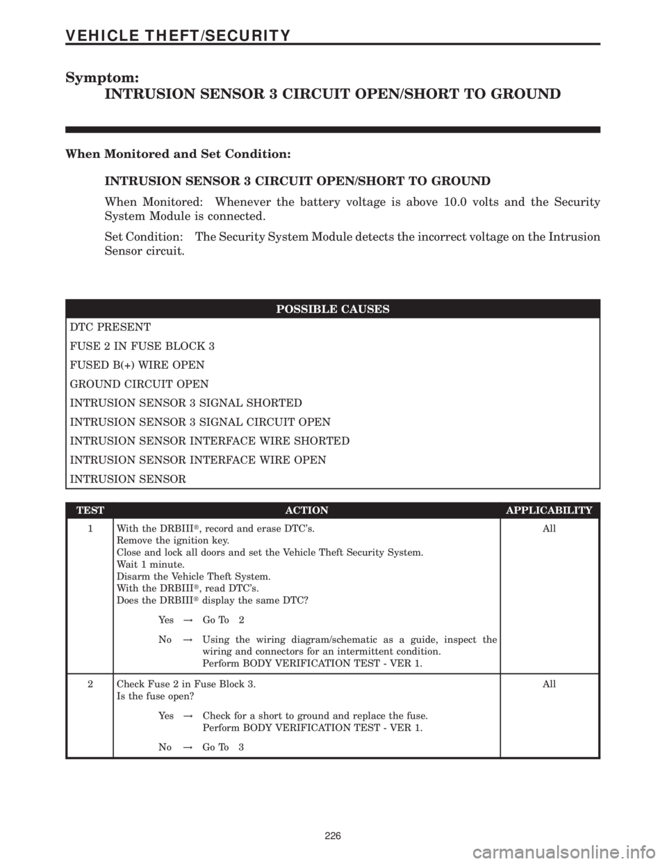
Symptom:
INTRUSION SENSOR 3 CIRCUIT OPEN/SHORT TO GROUND
When Monitored and Set Condition:
INTRUSION SENSOR 3 CIRCUIT OPEN/SHORT TO GROUND
When Monitored: Whenever the battery voltage is above 10.0 volts and the Security
System Module is connected.
Set Condition: The Security System Module detects the incorrect voltage on the Intrusion
Sensor circuit.
POSSIBLE CAUSES
DTC PRESENT
FUSE 2 IN FUSE BLOCK 3
FUSED B(+) WIRE OPEN
GROUND CIRCUIT OPEN
INTRUSION SENSOR 3 SIGNAL SHORTED
INTRUSION SENSOR 3 SIGNAL CIRCUIT OPEN
INTRUSION SENSOR INTERFACE WIRE SHORTED
INTRUSION SENSOR INTERFACE WIRE OPEN
INTRUSION SENSOR
TEST ACTION APPLICABILITY
1 With the DRBIIIt, record and erase DTC's.
Remove the ignition key.
Close and lock all doors and set the Vehicle Theft Security System.
Wait 1 minute.
Disarm the Vehicle Theft System.
With the DRBIIIt, read DTC's.
Does the DRBIIItdisplay the same DTC?All
Ye s!Go To 2
No!Using the wiring diagram/schematic as a guide, inspect the
wiring and connectors for an intermittent condition.
Perform BODY VERIFICATION TEST - VER 1.
2 Check Fuse 2 in Fuse Block 3.
Is the fuse open?All
Ye s!Check for a short to ground and replace the fuse.
Perform BODY VERIFICATION TEST - VER 1.
No!Go To 3
226
VEHICLE THEFT/SECURITY
Page 248 of 2305
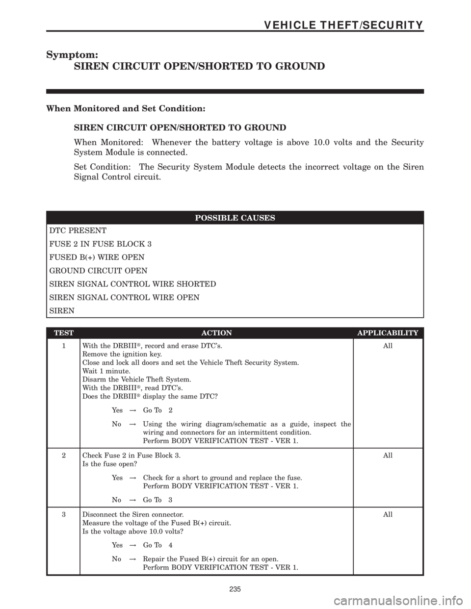
Symptom:
SIREN CIRCUIT OPEN/SHORTED TO GROUND
When Monitored and Set Condition:
SIREN CIRCUIT OPEN/SHORTED TO GROUND
When Monitored: Whenever the battery voltage is above 10.0 volts and the Security
System Module is connected.
Set Condition: The Security System Module detects the incorrect voltage on the Siren
Signal Control circuit.
POSSIBLE CAUSES
DTC PRESENT
FUSE 2 IN FUSE BLOCK 3
FUSED B(+) WIRE OPEN
GROUND CIRCUIT OPEN
SIREN SIGNAL CONTROL WIRE SHORTED
SIREN SIGNAL CONTROL WIRE OPEN
SIREN
TEST ACTION APPLICABILITY
1 With the DRBIIIt, record and erase DTC's.
Remove the ignition key.
Close and lock all doors and set the Vehicle Theft Security System.
Wait 1 minute.
Disarm the Vehicle Theft System.
With the DRBIIIt, read DTC's.
Does the DRBIIItdisplay the same DTC?All
Ye s!Go To 2
No!Using the wiring diagram/schematic as a guide, inspect the
wiring and connectors for an intermittent condition.
Perform BODY VERIFICATION TEST - VER 1.
2 Check Fuse 2 in Fuse Block 3.
Is the fuse open?All
Ye s!Check for a short to ground and replace the fuse.
Perform BODY VERIFICATION TEST - VER 1.
No!Go To 3
3 Disconnect the Siren connector.
Measure the voltage of the Fused B(+) circuit.
Is the voltage above 10.0 volts?All
Ye s!Go To 4
No!Repair the Fused B(+) circuit for an open.
Perform BODY VERIFICATION TEST - VER 1.
235
VEHICLE THEFT/SECURITY
Page 422 of 2305

TABLE OF CONTENTS - Continued
KICK DOWN SWITCH - BLACK...........................................271
MASS AIR FLOW SENSOR - BLACK......................................271
OXYGEN SENSOR (OBD)...............................................271
FUSED IGNITION SWITCH RUN-START RELAY (RELAY BLOCK)..............273
SPEED CONTROL SWITCH.............................................273
WATER IN FUEL SENSOR - BLACK.......................................273
10.0 SCHEMATIC DIAGRAMS................................................275
10.1ENGINE CONTROL MODULE.......................................275
10.2ENGINE CONTROL MODULE.......................................276
11.0 CHARTS AND GRAPHS................................................277
xi
Page 660 of 2305
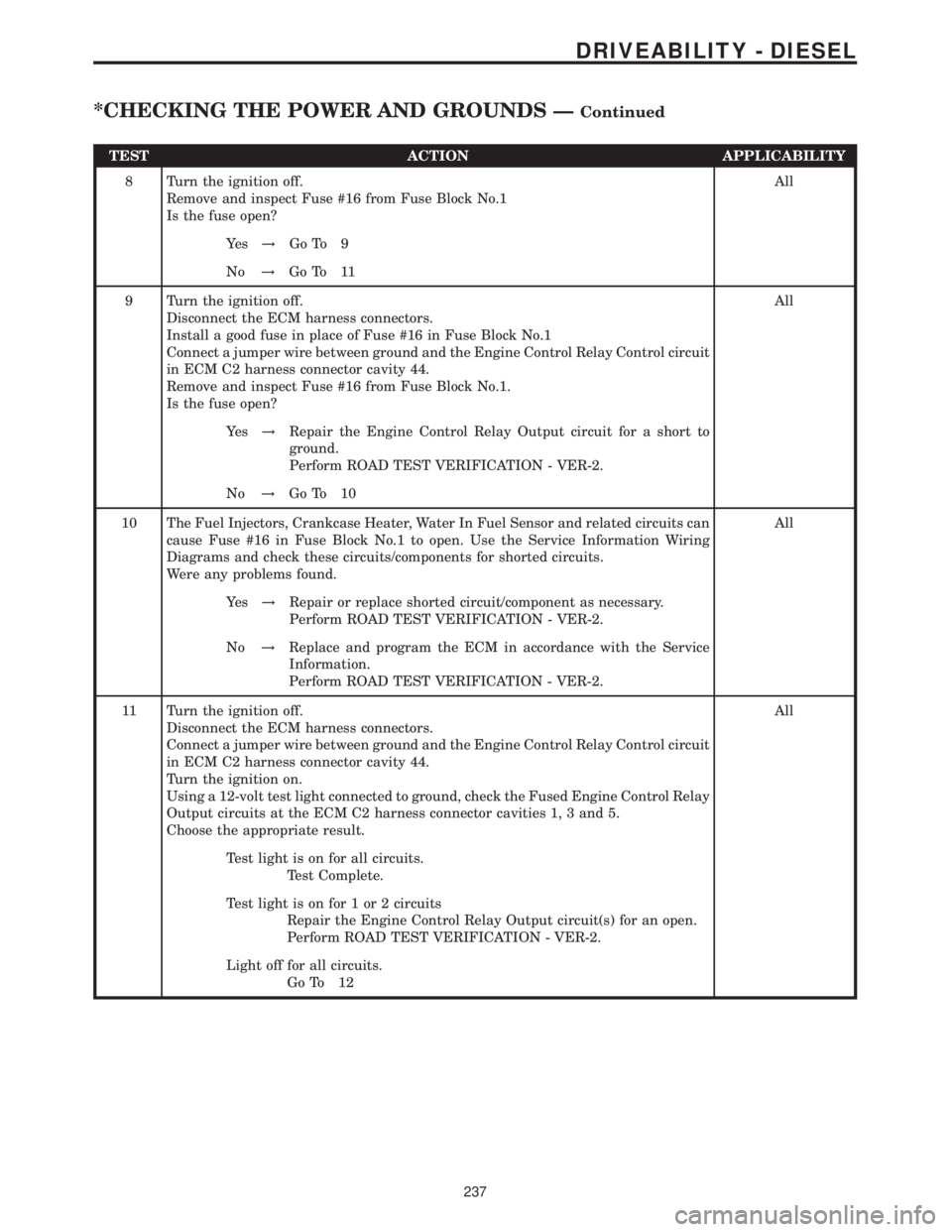
TEST ACTION APPLICABILITY
8 Turn the ignition off.
Remove and inspect Fuse #16 from Fuse Block No.1
Is the fuse open?All
Ye s!Go To 9
No!Go To 11
9 Turn the ignition off.
Disconnect the ECM harness connectors.
Install a good fuse in place of Fuse #16 in Fuse Block No.1
Connect a jumper wire between ground and the Engine Control Relay Control circuit
in ECM C2 harness connector cavity 44.
Remove and inspect Fuse #16 from Fuse Block No.1.
Is the fuse open?All
Ye s!Repair the Engine Control Relay Output circuit for a short to
ground.
Perform ROAD TEST VERIFICATION - VER-2.
No!Go To 10
10 The Fuel Injectors, Crankcase Heater, Water In Fuel Sensor and related circuits can
cause Fuse #16 in Fuse Block No.1 to open. Use the Service Information Wiring
Diagrams and check these circuits/components for shorted circuits.
Were any problems found.All
Ye s!Repair or replace shorted circuit/component as necessary.
Perform ROAD TEST VERIFICATION - VER-2.
No!Replace and program the ECM in accordance with the Service
Information.
Perform ROAD TEST VERIFICATION - VER-2.
11 Turn the ignition off.
Disconnect the ECM harness connectors.
Connect a jumper wire between ground and the Engine Control Relay Control circuit
in ECM C2 harness connector cavity 44.
Turn the ignition on.
Using a 12-volt test light connected to ground, check the Fused Engine Control Relay
Output circuits at the ECM C2 harness connector cavities 1, 3 and 5.
Choose the appropriate result.All
Test light is on for all circuits.
Test Complete.
Test light is on for 1 or 2 circuits
Repair the Engine Control Relay Output circuit(s) for an open.
Perform ROAD TEST VERIFICATION - VER-2.
Light off for all circuits.
Go To 12
237
DRIVEABILITY - DIESEL
*CHECKING THE POWER AND GROUNDS ÐContinued
Page 854 of 2305
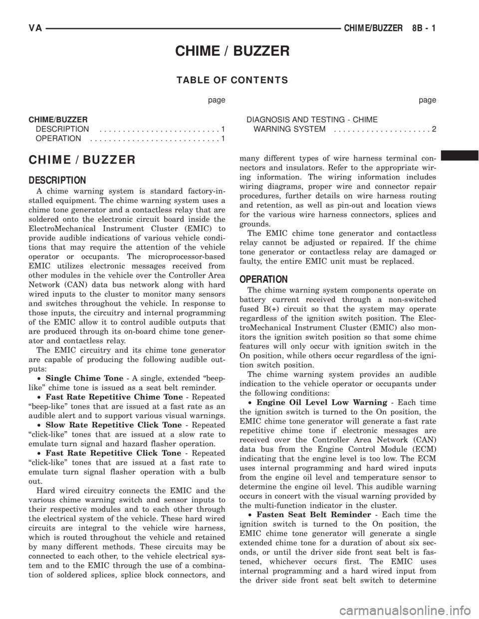
CHIME / BUZZER
TABLE OF CONTENTS
page page
CHIME/BUZZER
DESCRIPTION..........................1
OPERATION............................1DIAGNOSIS AND TESTING - CHIME
WARNING SYSTEM.....................2
CHIME / BUZZER
DESCRIPTION
A chime warning system is standard factory-in-
stalled equipment. The chime warning system uses a
chime tone generator and a contactless relay that are
soldered onto the electronic circuit board inside the
ElectroMechanical Instrument Cluster (EMIC) to
provide audible indications of various vehicle condi-
tions that may require the attention of the vehicle
operator or occupants. The microprocessor-based
EMIC utilizes electronic messages received from
other modules in the vehicle over the Controller Area
Network (CAN) data bus network along with hard
wired inputs to the cluster to monitor many sensors
and switches throughout the vehicle. In response to
those inputs, the circuitry and internal programming
of the EMIC allow it to control audible outputs that
are produced through its on-board chime tone gener-
ator and contactless relay.
The EMIC circuitry and its chime tone generator
are capable of producing the following audible out-
puts:
²Single Chime Tone- A single, extended ªbeep-
likeº chime tone is issued as a seat belt reminder.
²Fast Rate Repetitive Chime Tone- Repeated
ªbeep-likeº tones that are issued at a fast rate as an
audible alert and to support various visual warnings.
²Slow Rate Repetitive Click Tone- Repeated
ªclick-likeº tones that are issued at a slow rate to
emulate turn signal and hazard flasher operation.
²Fast Rate Repetitive Click Tone- Repeated
ªclick-likeº tones that are issued at a fast rate to
emulate turn signal flasher operation with a bulb
out.
Hard wired circuitry connects the EMIC and the
various chime warning switch and sensor inputs to
their respective modules and to each other through
the electrical system of the vehicle. These hard wired
circuits are integral to the vehicle wire harness,
which is routed throughout the vehicle and retained
by many different methods. These circuits may be
connected to each other, to the vehicle electrical sys-
tem and to the EMIC through the use of a combina-
tion of soldered splices, splice block connectors, andmany different types of wire harness terminal con-
nectors and insulators. Refer to the appropriate wir-
ing information. The wiring information includes
wiring diagrams, proper wire and connector repair
procedures, further details on wire harness routing
and retention, as well as pin-out and location views
for the various wire harness connectors, splices and
grounds.
The EMIC chime tone generator and contactless
relay cannot be adjusted or repaired. If the chime
tone generator or contactless relay are damaged or
faulty, the entire EMIC unit must be replaced.
OPERATION
The chime warning system components operate on
battery current received through a non-switched
fused B(+) circuit so that the system may operate
regardless of the ignition switch position. The Elec-
troMechanical Instrument Cluster (EMIC) also mon-
itors the ignition switch position so that some chime
features will only occur with ignition switch in the
On position, while others occur regardless of the igni-
tion switch position.
The chime warning system provides an audible
indication to the vehicle operator or occupants under
the following conditions:
²Engine Oil Level Low Warning- Each time
the ignition switch is turned to the On position, the
EMIC chime tone generator will generate a fast rate
repetitive chime tone if electronic messages are
received over the Controller Area Network (CAN)
data bus from the Engine Control Module (ECM)
indicating that the engine level is too low. The ECM
uses internal programming and hard wired inputs
from the engine oil level and temperature sensor to
determine the engine oil level. This audible warning
occurs in concert with the visual warning provided by
the multi-function indicator in the cluster.
²Fasten Seat Belt Reminder- Each time the
ignition switch is turned to the On position, the
EMIC chime tone generator will generate a single
extended chime tone for a duration of about six sec-
onds, or until the driver side front seat belt is fas-
tened, whichever occurs first. The EMIC uses
internal programming and a hard wired input from
the driver side front seat belt switch to determine
VACHIME/BUZZER 8B - 1
Page 903 of 2305
relays which allows battery current to flow to the
rear window defogger grid lines. The heated grid
lines heat the rear glass to help clear the rear win-
dow surfaces of fog or frost.
The electric backlight (EBL) system is controlled
by the EBL timing circuity, which is integral to the
rear window defogger module. A yellow indicator in
the switch will illuminate to indicate when the EBL
system is turned on.
NOTE: The EBL system turns off automatically after
approximately 10 minutes of initial operation. Each
following activation cycle of the EBL system will
last approximately five minutes.
The EBL system will be automatically turned off
after a programmed time interval of about ten min-
utes. After the initial time interval has expired, if the
rear window defogger switch is pressed to the On
position again during the same ignition cycle, the
EBL system will automatically turn off after about
five minutes.
The EBL system will automatically shut off if the
ignition switch is turned to the Off position, or it can
be turned off manually by pressing the defogger
switch a second time.
DIAGNOSIS AND TESTING
ELECTRIC BACKLIGHT (EBL) SYSTEM
NOTE: Illumination of the defogger switch indicator
lamp means that there is electrical current available
at the output of the rear window defogger logic cir-
cuitry, but does not confirm that the electrical cur-
rent is reaching the rear glass heating grid lines.
NOTE: For circuit descriptions and diagrams of the
EBL system, refer to 8W - WIRING DIAGRAM
INFORMATION.
Operation of the electrical backlight (EBL) system
can be confirmed by the following:
(1) Turn the ignition switch to the On position. Set
the rear window defogger switch in the On position.
The rear window defogger operation can be checked
by feeling the rear window glass. A distinct difference
in temperature between the grid lines and the adja-
cent clear glass should be detected within three to
four minutes of operation.
(2) If a temperature difference is not detected, use
a 12-volt DC voltmeter and contact the rear glass
heating grid terminal B with the negative lead, and
terminal A with the positive lead (Fig. 2). The volt-
meter should read battery voltage. If the voltmeter
does not read battery voltage, check the following:²Confirm that the ignition switch is in the On
position.
²Make sure that the rear glass heating grid feed
wires and ground wires are connected to the window
terminals. Confirm that the ground wires have conti-
nuity to ground.
²Check that fuse 7 (15 amp) in fuse block #1 and
fuse 10 (30 amp) in the fuse/relay block are OK. The
fuses must be tight in there receptacles and all elec-
trical connections must be secure.
(3) When the above steps have been completed and
the rear glass heating grid is still inoperative, one or
more of the following is faulty.
²Rear window defogger switch in the instrument
panel.
²Rear window defogger (EBL) relays in the fuse/
relay block.
²Rear window defogger (EBL) relay control circu-
ity in the rear window defogger module.
²Check for a loose wire connector or a wire
pushed out of a connector.
²Rear window grid lines (all grid lines would
have to be broken, or the power feed or ground wire
not connected, for the entire heating grid to be inop-
erative).
(4) If the system operation has been verified but
the defogger switch indicator does not illuminate,
check for voltage at the defogger indicator from the
rear window defogger module when the defogger
switch is activated. If power is present, replace the
rear window defogger switch.
(5) If broken defogger grid lines are suspected, use
a 12-volt DC voltmeter and contact terminal B with
the negative lead and each rear glass heating grid
line at it's mid-point with the positive lead. The volt-
meter should read approximately 6 volts at each grid
line mid-point C. If the voltmeter does not read
approximately 6 volts, repair the open grid line(s)
(Refer to 8 - ELECTRICAL/HEATED GLASS/REAR
WINDOW DEFOGGER GRID - STANDARD PROCE-
DURE).
8G - 2 HEATED GLASSVA