warning MERCEDES-BENZ SPRINTER 2006 Service Manual
[x] Cancel search | Manufacturer: MERCEDES-BENZ, Model Year: 2006, Model line: SPRINTER, Model: MERCEDES-BENZ SPRINTER 2006Pages: 2305, PDF Size: 48.12 MB
Page 3 of 2305
CAUTION
ALL SERVICE AND REBUILDING INSTRUCTIONS CONTAINED HEREIN
ARE APPLICABLE TO, AND FOR THE CONVENIENCE OF, THE AUTOMOTIVE
TRADE ONLY. All test and repair procedures on components or assemblies
innon-automotive applications should be repaired in accordance with instruc-
tions supplied by the manufacturer of the total product.
Proper service and repair is important to the safe, reliable, operation of all motor vehicles. The
service procedures recommended and described in this publication were developed for pro-
fessional service personnel and are effective methods for performing vehicle repair. Following
these procedures will help assure efficient economical vehicle performance and service reli-
ability. Some of these service procedures require the use of special tools designed for specific
procedures. These special tools should be used when recommended throughout this publi-
cation.
Special attention should be exercised when working with spring or tension loaded
fasteners and devices such as E-Clips, Circlips, Snap rings, etc., as careless
removal may cause personal injury. Always wear safety goggles whenever work-
ing on vehicles or vehicle components.
It is important to note that this publication contains various CautionsandWarnings. These
should be carefully read in order to minimize the risk of personal injury, or the possibility that
improper service methods may damage the vehicle or render it unsafe. It is important to note
that these CautionsandWarnings cover only the situations and procedures Daimler-
Chrysler Corporation has encountered and recommended.
DaimlerChrysler Corporation
could not possibly know, evaluate, and advise the
service trade of all conceivable ways that
service may be performed, or of the possible hazards of each. Consequently, DaimlerChrysler
Corporation has not undertaken any such broad service review. Accordingly, anyone who uses
a service procedure, or tool, that is not recommended in this publication must assure oneself
thoroughly that neither personal safety, nor vehicle safety, be jeopardized by the service
methods they select.
For other Service and Owner Manuals for Chrysler,
Plymouth, Dodge, Dodge Truck, and Jeep
Tvehicles, Call
(800) 890-4038 or FAX (440) 572-0815 to place an order. Or, visit our website at techauthority.daimlerchrysler.com.Tech Authority Online at our website offers you serviceinformation on a subscription basis.
Page 6 of 2305
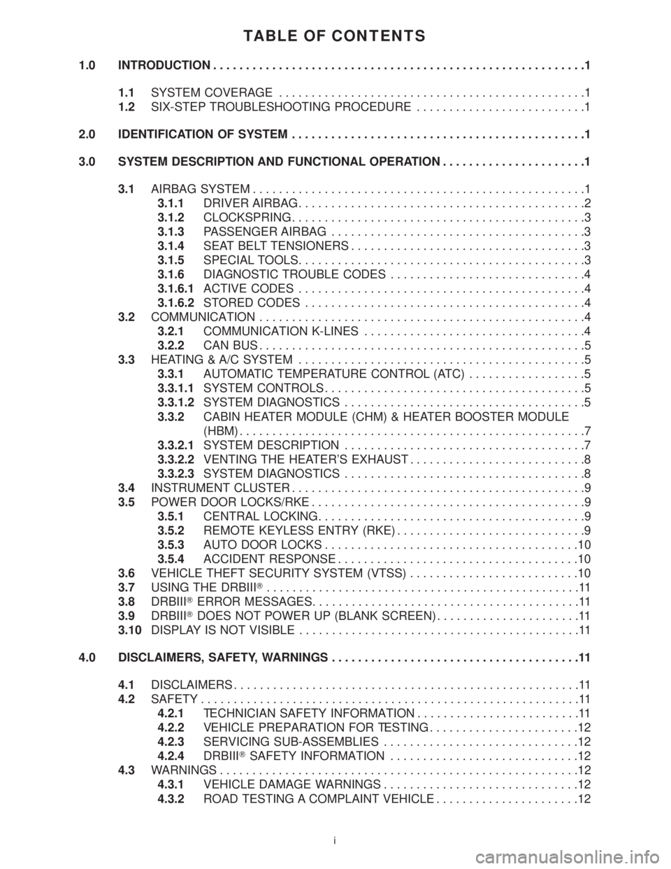
TABLE OF CONTENTS
1.0 INTRODUCTION.........................................................1
1.1SYSTEM COVERAGE...............................................1
1.2SIX-STEP TROUBLESHOOTING PROCEDURE..........................1
2.0 IDENTIFICATION OF SYSTEM.............................................1
3.0 SYSTEM DESCRIPTION AND FUNCTIONAL OPERATION......................1
3.1AIRBAG SYSTEM...................................................1
3.1.1DRIVER AIRBAG............................................2
3.1.2CLOCKSPRING.............................................3
3.1.3PASSENGER AIRBAG.......................................3
3.1.4SEAT BELT TENSIONERS....................................3
3.1.5SPECIAL TOOLS............................................3
3.1.6DIAGNOSTIC TROUBLE CODES..............................4
3.1.6.1ACTIVE CODES............................................4
3.1.6.2STORED CODES...........................................4
3.2COMMUNICATION..................................................4
3.2.1COMMUNICATION K-LINES..................................4
3.2.2CAN BUS..................................................5
3.3HEATING & A/C SYSTEM............................................5
3.3.1AUTOMATIC TEMPERATURE CONTROL (ATC)..................5
3.3.1.1SYSTEM CONTROLS........................................5
3.3.1.2SYSTEM DIAGNOSTICS.....................................5
3.3.2CABIN HEATER MODULE (CHM) & HEATER BOOSTER MODULE
(HBM).....................................................7
3.3.2.1SYSTEM DESCRIPTION.....................................7
3.3.2.2VENTING THE HEATER'S EXHAUST...........................8
3.3.2.3SYSTEM DIAGNOSTICS.....................................8
3.4INSTRUMENT CLUSTER.............................................9
3.5POWER DOOR LOCKS/RKE..........................................9
3.5.1CENTRAL LOCKING.........................................9
3.5.2REMOTE KEYLESS ENTRY (RKE).............................9
3.5.3AUTO DOOR LOCKS.......................................10
3.5.4ACCIDENT RESPONSE.....................................10
3.6VEHICLE THEFT SECURITY SYSTEM (VTSS)..........................10
3.7USING THE DRBIIIT................................................11
3.8DRBIIITERROR MESSAGES.........................................11
3.9DRBIIITDOES NOT POWER UP (BLANK SCREEN)......................11
3.10DISPLAY IS NOT VISIBLE...........................................11
4.0 DISCLAIMERS, SAFETY, WARNINGS......................................11
4.1DISCLAIMERS.....................................................11
4.2SAFETY..........................................................11
4.2.1TECHNICIAN SAFETY INFORMATION.........................11
4.2.2VEHICLE PREPARATION FOR TESTING.......................12
4.2.3SERVICING SUB-ASSEMBLIES..............................12
4.2.4DRBIIITSAFETY INFORMATION.............................12
4.3WARNINGS.......................................................12
4.3.1VEHICLE DAMAGE WARNINGS..............................12
4.3.2ROAD TESTING A COMPLAINT VEHICLE......................12
i
Page 7 of 2305
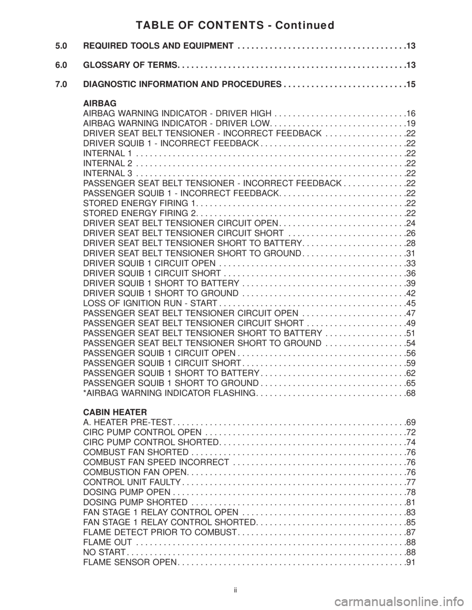
TABLE OF CONTENTS - Continued
5.0 REQUIRED TOOLS AND EQUIPMENT.....................................13
6.0 GLOSSARY OF TERMS..................................................13
7.0 DIAGNOSTIC INFORMATION AND PROCEDURES...........................15
AIRBAG
AIRBAG WARNING INDICATOR - DRIVER HIGH.............................16
AIRBAG WARNING INDICATOR - DRIVER LOW..............................19
DRIVER SEAT BELT TENSIONER - INCORRECT FEEDBACK..................22
DRIVER SQUIB 1 - INCORRECT FEEDBACK................................22
INTERNAL 1...........................................................22
INTERNAL 2...........................................................22
INTERNAL 3...........................................................22
PASSENGER SEAT BELT TENSIONER - INCORRECT FEEDBACK..............22
PASSENGER SQUIB 1 - INCORRECT FEEDBACK............................22
STORED ENERGY FIRING 1..............................................22
STORED ENERGY FIRING 2..............................................22
DRIVER SEAT BELT TENSIONER CIRCUIT OPEN............................24
DRIVER SEAT BELT TENSIONER CIRCUIT SHORT..........................26
DRIVER SEAT BELT TENSIONER SHORT TO BATTERY.......................28
DRIVER SEAT BELT TENSIONER SHORT TO GROUND.......................31
DRIVER SQUIB 1 CIRCUIT OPEN.........................................33
DRIVER SQUIB 1 CIRCUIT SHORT........................................36
DRIVER SQUIB 1 SHORT TO BATTERY....................................39
DRIVER SQUIB 1 SHORT TO GROUND....................................42
LOSS OF IGNITION RUN - START.........................................45
PASSENGER SEAT BELT TENSIONER CIRCUIT OPEN.......................47
PASSENGER SEAT BELT TENSIONER CIRCUIT SHORT......................49
PASSENGER SEAT BELT TENSIONER SHORT TO BATTERY..................51
PASSENGER SEAT BELT TENSIONER SHORT TO GROUND..................54
PASSENGER SQUIB 1 CIRCUIT OPEN.....................................56
PASSENGER SQUIB 1 CIRCUIT SHORT....................................59
PASSENGER SQUIB 1 SHORT TO BATTERY................................62
PASSENGER SQUIB 1 SHORT TO GROUND................................65
*AIRBAG WARNING INDICATOR FLASHING.................................68
CABIN HEATER
A. HEATER PRE-TEST...................................................69
CIRC PUMP CONTROL OPEN............................................72
CIRC PUMP CONTROL SHORTED.........................................74
COMBUST FAN SHORTED...............................................76
COMBUST FAN SPEED INCORRECT......................................76
COMBUSTION FAN OPEN................................................76
CONTROL UNIT FAULTY.................................................77
DOSING PUMP OPEN...................................................78
DOSING PUMP SHORTED...............................................81
FAN STAGE 1 RELAY CONTROL OPEN....................................83
FAN STAGE 1 RELAY CONTROL SHORTED.................................85
FLAME DETECT PRIOR TO COMBUST.....................................87
FLAME OUT...........................................................88
NO START.............................................................88
FLAME SENSOR OPEN..................................................91
ii
Page 14 of 2305
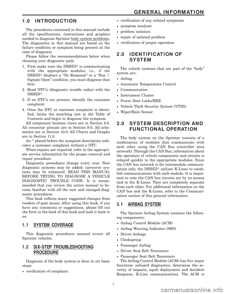
1.0 INTRODUCTION
The procedures contained in this manual include
all the specifications, instructions and graphics
needed to diagnose Sprinter body system problems.
The diagnostics in this manual are based on the
failure condition or symptom being present at the
time of diagnosis.
Please follow the recommendations below when
choosing your diagnostic path.
1. First make sure the DRBIIItis communicating
with the appropriate modules; i.e., if the
DRBIIItdisplays a ``No Response'' or a ``Bus6
Signals Open'' condition, you must diagnose that
first.
2. Read DTC's (diagnostic trouble codes) with the
DRBIIIt.
3. If no DTC's are present, identify the customer
complaint.
4. Once the DTC or customer complaint is identi-
fied, locate the matching test in the Table of
Contents and begin to diagnose the symptom.
All component location views are in Section 8.0.
All connector pinouts are in Section 9.0. All sche-
matics are in Section 10.0. All Charts and Graphs
are in Section 11.0.
An * placed before the symptom description indi-
cates a customer complaint without a DTC.
When repairs are required, refer to the appropri-
ate service information for the proper removal and
repair procedure.
Diagnostic procedures change every year. New
diagnostic systems may be added: carryover sys-
tems may be enhanced. READ THIS MANUAL
BEFORE TRYING TO DIAGNOSE A VEHICLE
DIAGNOSTIC TROUBLE CODE. It is recom-
mended that you review the entire manual to be-
come familiar with all the new and changed diag-
nostic procedures.
This book reflects many suggested changes from
readers of past issues. After using this book, if you
have any comments or suggestions, please fill out
the form in the back of this book and mail it back to
us.
1.1 SYSTEM COVERAGE
This diagnostic procedures manual covers all
Sprinter vehicles.
1.2 SIX-STEP TROUBLESHOOTING
PROCEDURE
Diagnosis of the body system is done in six basic
steps:
²verification of complaint
²verification of any related symptoms
²symptom analysis
²problem isolation
²repair of isolated problem
²verification of proper operation
2.0 IDENTIFICATION OF
SYSTEM
The vehicle systems that are part of the ``body''
system are:
²Airbag
²Automatic Temperature Control
²Communication
²Instrument Cluster
²Power Door Locks/RKE
²Vehicle Theft Security System (VTSS)
²Wiper/Rain Sensor
3.0 SYSTEM DESCRIPTION AND
FUNCTIONAL OPERATION
The body system on the Sprinter consists of a
combination of modules that communicate with
each other using the CAN Bus (controller area
network). Through the CAN Bus, information about
the operation of vehicle components and circuits is
relayed quickly to the appropriate modules. Since
the CAN bus network is for intermodule communi-
cation only, the DRBIIItutilizes K-Lines to estab-
lish communications with each module. It is impor-
tant to note the CAN bus circuits are by no means
tied to the K-Lines. They are completely separate
from each other. For additional information on the
CAN bus and the K-Lines, refer to the Communi-
cation section of this general information.
3.1 AIRBAG SYSTEM
The Sprinter Airbag System contains the follow-
ing components:
²Airbag Control Module (ACM)
²Airbag Warning Indicator (SRS)
²Driver Airbags
²Clockspring
²Passenger Airbag
²Driver Seat Belt Tensioners
²Passenger Seat Belt Tensioners
The Airbag Control Module (ACM) has five major
functions: onboard diagnostics, determine the se-
verity of impacts, squib deployment and Accident
Response, K-Line communications. The ACM is
1
GENERAL INFORMATION
Page 15 of 2305
secured to the floor under the Driver seat and
receives power from the Fuse Block No. 1. When-
ever the ignition key is turned to the run or start
position, the ACM performs a system test. The ACM
cannot be repaired or adjusted.
The microprocessor in the ACM monitors the
internal and external airbag system electrical cir-
cuits to determine the system readiness. When a
monitored system is determine to be out of range,
the ACM will set both active and stored diagnostic
trouble codes (DTC). The ACM also contains an
energy-storage capacitor. This capacitor stores
enough electrical energy to deploy the front airbag
components for two seconds following a battery
disconnect or failure during an impact.
The Accelerometer in the ACM is used to sense
the rate of vehicle deceleration, provide verification
of the direction and severity of an impact. When the
preprogrammed conditions are met, the ACM sends
an electrical signal to deploy the appropriate front
airbag system components and a deployment noti-
fication.
To provide an accident response notification, the
ACM is hardwired to the Central Timer module
(CTM) and Engine Control Module (ECM). When a
deployment occurs the ACM provides a 50ms 10.0
volt pulse to the CTM and ECM. When the Accident
Report notification signal is received the CTM un-
locks the door locks and the ECM stalls the engine.
The Accident signal will set a DTC in the CTM and
the door locks will not work until the DTC has been
erased. The ECM will set a DTC if the Accident
Report circuit is shorted to battery voltage. The
ACM saves the deployment record and after three
deployments the ACM must be replaced. The
DRBIIItcan be used to test the Accident Report
Notification feature: select the SYSTEM TEST from
the ACM main menu. Then select the Analog Crash
Output System Test.
The ACM is hardwired to the Instrument Cluster
(MIC) to control Warning Indicator (SRS indicator).
When DTCs becomes activate, the ACM illuminates
the Warning Indicator by pulling the indicator
circuit low. The SRS indicator is the only point at
which the customer can observe symptoms of a
system malfunction.
As part of the system test the ACM illuminates
the Warning Indicator on for 4.0 second bulb test.
After the lamp check, if the indicator turns off, it
means that the ACM has checked the system and
found it to be free of discernible malfunctions.
NON-CRITICAL DTCs
If the lamp comes on and stays on for a period
longer than 4.0 seconds (about 10.0 seconds) is
usually a stored DTC (intermittent problem) in the
system.
CRITICAL DTCs
DTCs that could lead to a condition where the
safety devises may not deploy or incorrectly deploy.
In the event of such a DTC, the safety of the vehicle
occupants can no longer be guaranteed. If the lamp
remains on, there could be an active DTC in the
system. Some DTCs, Internal Module and squib
DTCs, will keep the indicator illuminated even if
the codes are no longer active.
ACM NOT CONFIGURED FOR PASSENGER
AIRBAG AND TENSIONER
If after replacing the ACM the Airbag Warning
Indicator flashes continuously the ACM must be
configured for the Passenger Airbag and Tensioner.
Select Miscellaneous from the ACM main menu and
configure the Passenger Airbag Tensioner squibs.
WARNING:THE AIRBAG SYSTEM IS A
SENSITIVE, COMPLEX ELECTROMECHANICAL
UNIT. BEFORE ATTEMPTING TO DIAGNOSE OR
SERVICE ANY AIRBAG SYSTEM OR RELATED
STEERING WHEEL, STEERING COLUMN, OR
INSTRUMENT PANEL COMPONENTS YOU MUST
FIRST DISCONNECT AND ISOLATE THE
BATTERY NEGATIVE (GROUND) CABLE. WAIT
TWO MINUTES FOR THE SYSTEM CAPACITOR
TO DISCHARGE BEFORE FURTHER SYSTEM
SERVICE. THIS IS THE ONLY SURE WAY TO
DISABLE THE AIRBAG SYSTEM. FAILURE TO
DO THIS COULD RESULT IN ACCIDENTAL
AIRBAG DEPLOYMENT AND POSSIBLE
PERSONAL INJURY.
WARNING: TO AVOID PERSONAL INJURY OR
DEATH, NEVER STRIKE OR KICK THE
AIRBAG CONTROL MODULE, AS IT CAN
DAMAGE THE IMPACT SENSOR OR AFFECT
ITS CALIBRATION.
WARNING: IF AN AIRBAG CONTROL
MODULE IS ACCIDENTALLY DROPPED
DURING SERVICE, THE MODULE MUST BE
SCRAPPED AND REPLACED WITH A NEW
UNIT. FAILURE TO TAKE THE PROPER
PRECAUTIONS COULD RESULT IN
ACCIDENTAL AIRBAG DEPLOYMENT AND
PERSONAL INJURY OR DEATH.
3.1.1 DRIVER AIRBAG
The airbag protective trim cover is the most
visible part of the driver side airbag system. The
airbag is mounted directly to the steering wheel.
Located under the trim cover are the airbag cushion
and the airbag cushion supporting components.
2
GENERAL INFORMATION
Page 16 of 2305
When supplied with the proper electrical signal, the
inflator discharged the gas directly into the cush-
ion. The airbag cannot be repaired, and must be
replaced if deployed or in any way damaged.
WARNING: THE DRIVER AIRBAG MODULE
CONTAINS ARGON GAS PRESSURIZED TO
OVER 17236.89 Kpa (2500 PSI). DO NOT
ATTEMPT TO DISMANTLE AN AIRBAG
MODULE OR TAMPER WITH ITS INFLATOR.
DO NOT PUNCTURE, INCINERATE, OR
BRING INTO CONTACT WITH ELECTRICITY.
DO NOT STORE AT TEMPERATURE
EXCEEDING 93ÉC (200ÉF). REPLACE AIRBAG
SYSTEM COMPONENTS ONLY WITH PARTS
SPECIFIED IN THE CHRYSLER MOPAR
PARTS CATALOG. SUBSTITUTE PARTS MAY
APPEAR INTER-CHANGEABLE, BUT
INTERNAL DIFFERENCES MAY RESULT IN
INFERIOR OCCUPANT PROTECTION. THE
FASTENERS, SCREWS, AND BOLTS
ORIGINALLY USED FOR THE AIRBAG
SYSTEM COMPONENTS HAVE SPECIAL
COATINGS AND ARE SPECIFICALLY
DESIGNED FOR THE AIRBAG SYSTEM. THEY
MUST NEVER BE REPLACED WITH ANY
SUBSTITUTES. ANY TIME A NEW FASTENER
IS NEEDED, REPLACE IT WITH THE
CORRECT FASTENERS PROVIDED IN THE
SERVICE PACKAGE OR SPECIFIED IN THE
MOPAR PARTS CATALOG. FAILURE TO
TAKE THE PROPER PRECAUTIONS COULD
RESULT IN ACCIDENTAL AIRBAG
DEPLOYMENT AND PERSONAL INJURY OR
DEATH.
3.1.2 CLOCKSPRING
The clockspring is mounted on the steering col-
umn under the steering wheel. This assembly con-
sists of a plastic housing which contains a flat,
ribbon-like, electrically conductive tape that winds
and unwinds with the steering wheel rotation. The
clockspring is used to maintain a continuous elec-
trical circuit between the instrument panel wiring
and the driver airbag and the horn. The clockspring
must be properly centered when it is reinstalled on
the steering column following any service proce-
dure, or it could be damaged. The clockspring can-
not be repaired and it must be replaced.
3.1.3 PASSENGER AIRBAG
The Passenger Airbag is optional equipment.
When supplied with the proper electrical signal the
passenger airbag inflator discharges the gas di-rectly into the cushion. The airbag module cannot
be repaired, and must be replaced if deployed or in
any way damaged.
WARNING: THE PASSENGER AIRBAG
MODULE CONTAINS ARGON GAS
PRESSURIZED TO 17236.89 Kpa (2500 PSI).
DO NOT ATTEMPT TO DISMANTLE AN
AIRBAG MODULE OR TAMPER WITH ITS
INFLATOR. DO NOT PUNCTURE,
INCINERATE, OR BRING INTO CONTACT
WITH ELECTRICITY. DO NOT STORE AT
TEMPERATURE EXCEEDING 93ÉC (200ÉF).
REPLACE AIRBAG SYSTEM COMPONENTS
ONLY WITH PARTS SPECIFIED IN THE
MOPAR PARTS CATALOG. SUBSTITUTE
PARTS MAY APPEAR INTER-CHANGEABLE,
BUT INTERNAL DIFFERENCES MAY RESULT
IN INFERIOR OCCUPANT PROTECTION. THE
FASTENERS, SCREWS, AND BOLTS
ORIGINALLY USED FOR THE AIRBAG
SYSTEM COMPONENTS HAVE SPECIAL
COATINGS AND ARE SPECIFICALLY
DESIGNED FOR THE AIRBAG SYSTEM. THEY
MUST NEVER BE REPLACED WITH ANY
SUBSTITUTES. ANY TIME A NEW FASTENER
IS NEEDED, REPLACE IT WITH THE
CORRECT FASTENERS PROVIDED IN THE
SERVICE PACKAGE OR SPECIFIED IN THE
MOPAR PARTS CATALOG. FAILURE TO
TAKE THE PROPER PRECAUTIONS COULD
RESULT IN ACCIDENTAL AIRBAG
DEPLOYMENT AND PERSONAL INJURY OR
DEATH.
3.1.4 SEAT BELT TENSIONERS
Front seat belt systems incorporate a Driver and
optional Passenger Seat Belt Tensioner Retractors.
At the onset of an impact event each tensioner uses
a pyrotechnic device, which is triggered simulta-
neously with the front airbags, to rapidly retract
the seat belts. With the slack removed, the occu-
pant's forward motion in an impact will be reduced
as will the likelihood of contacting interior compo-
nents. After an impact that deploys the airbag, the
seat belt tensioner assembly must be replaced. The
ACM module monitors the Seat Belt Tensioners
circuit resistance and reports active and stored
DTCs if any problem is found. Follow all of the
safety procedures when servicing tensioner.
3.1.5 SPECIAL TOOLS
Airbag load tools 8310 and 8443 are used in some
airbag diagnostic test. The load tools contain fixed
resistive loads, jumpers and adapters. The fixed
3
GENERAL INFORMATION
Page 20 of 2305
Compres SO Accel (Compressor Shut Off - Due
To Acceleration)
The Engine Control Module transmits this data. A
status of9YES9indicates that the compressor shut
off because of an acceleration request. A status of
9NO9indicates that there is no acceleration request.
If shut off due to an acceleration request, the
compress will switch on again after 20 seconds. In
addition, the original acceleration request can no
longer exist for the ECM to acknowledge a subse-
quent request. In the event of a CAN Bus commu-
nication failure,9NO9is displayed as a substitute
value.
Compres SO W/E-Off (Compressor Shut Off -
Due to Emergency Off)
The Engine Control Module transmits this data. A
status of9YES9indicates that the compressor shut
off because of an emergency off request. A status of
9NO9indicates that there is no emergency off re-
quest. In the event of a CAN Bus communication
failure, the last stored value is displayed as a
substitute value.
Auxiliary Fan
The ATC Module transmits this data. A status of
9ON9indicates that the auxiliary fan is operational.
A status of9OFF9indicates that the auxiliary fan is
not operational. The Auxiliary Fan normally oper-
ates when refrigerant head pressure exceeds 290
PSI and coolant temperature exceeds 221ÉF. In the
event of a CAN Bus communication failure, 257ÉF is
displayed for coolant temperature (in Sensors) and
the Auxiliary Fan will run continuously.
Light PB CTRL Module
This input displays a status of9Bright9for positive
dimmer switch operation and9Dimmed9for nega-
tive dimmer switch operation. In the event of a CAN
Bus communication failure,9Bright9is displayed.
3.3.2 CABIN HEATER MODULE (CHM) &
HEATER BOOSTER MODULE (HBM)
3.3.2.1 SYSTEM DESCRIPTION
WARNING: NEVER OPERATE THE HEATER
IN AN ENCLOSED AREA THAT DOES NOT
HAVE EXHAUST VENTILATION FACILITIES.
ALWAYS VENT THE HEATER'S EXHAUST
WHEN OPERATING THE HEATER. REFER TO
(VENTING THE HEATER'S EXHAUST(
BELOW FOR PROPER EXHAUST VENTING
INSTRUCTIONS. FAILURE TO FOLLOW
THESE INSTRUCTIONS CAN RESULT IN
PERSONAL INJURY OR DEATH.
WARNING: ALLOW THE HEATER ASSEMBLY TO
COOL BEFORE PERFORMING A COMPONENT
INSPECTION/REPAIR/REPLACEMENT. FAILURE
TO FOLLOW THESE INSTRUCTIONS CAN
RESULT IN PERSONAL INJURY OR DEATH.
WARNING: ALWAYS DISCONNECT THE
VEHICLE'S BATTERY PRIOR TO
PERFORMING ANY TYPE OF WORK ON THE
HEATER ASSEMBLY. FAILURE TO FOLLOW
THESE INSTRUCTIONS CAN RESULT IN
PERSONAL INJURY OR DEATH.
WARNING: NEVER ATTEMPT TO REPAIR THE
HEATER ASSEMBLY OR ANY OF ITS
INTERNAL COMPONENTS. ALWAYS
PERFORM HEATER COMPONENT
REPLACEMENT IN ACCORDANCE WITH THE
SERVICE INFORMATION. FAILURE TO
FOLLOW THESE INSTRUCTIONS CAN
RESULT IN PERSONAL INJURY OR DEATH.
CAUTION: Always Perform The Heater
Pre-Test (In The Diagnostic Procedures) Prior
To Performing Any Other Test On The Heater
For The Test Result To Be Valid.
NOTE: Do not disconnect the vehicle's
battery or the heater's main power-supply
while the heater is in operation or in
run-down mode. Failure to follow these
instructions may result in excess emissions
from the heater.
NOTE: Failure to prime the Dosing Pump
after draining the fuel line will prevent heater
activation during the first attempt to start the
unit. This may also set a Diagnostic Trouble
Code (DTC) in the control unit's memory. Do
not perform the Dosing Pump Priming
Procedure if an attempt was made to start the
heater without priming the Dosing Pump
first. This will put excess fuel in the heater
module and cause smoke to emit from the
heater's exhaust pipe when heater activation
occurs.
NOTE: Waxed fuel can obstruct the fuel line
and reduce flow. Check for the appropriate
winter grade fuel and replace as necessary.
The Cabin Heater Assembly and Heater Booster
Assembly are supplemental type heaters designed
to pre-heat the engine's coolant in order to supply
the vehicle's occupants with heat prior to the engine
7
GENERAL INFORMATION
Page 21 of 2305
reaching operating temperature. The heater's con-
trol unit controls and monitors combustion opera-
tion through various inputs and outputs that are
contained inside the heater assembly. The supple-
mental heater connects to the vehicle's heater hoses
and uses a separate fuel supply line and fuel pump
that connects to the vehicle's fuel tank. Unlike the
Heater Booster, the Cabin Heater Assembly has an
integral coolant pump which allows heater opera-
tion without the vehicle's engine running. In addi-
tion, a programmable timer module can also be
added to this system. Neither the Cabin Heater
Assembly nor the Heater Booster Assembly are
connected to the CAN Bus. Communication be-
tween the heater's control unit and the DRBIIIt
occurs through the Diagnostic Link Connector
(DLC) via a K-Line.
3.3.2.2 VENTING THE HEATER'S EXHAUST
WARNING: NEVER OPERATE THE HEATER
IN AN ENCLOSED AREA THAT DOES NOT
HAVE EXHAUST VENTILATION FACILITIES.
ALWAYS VENT THE HEATER'S EXHAUST
WHEN OPERATING THE HEATER. FAILURE
TO FOLLOW THESE INSTRUCTIONS CAN
RESULT IN PERSONAL INJURY OR DEATH.
WARNING:
ALLOW THE HEATER ASSEMBLY TO
COOL BEFORE PERFORMING A COMPONENT
INSPECTION/REPAIR/REPLACEMENT. FAILURE
TO FOLLOW THESE INSTRUCTIONS CAN
RESULT IN PERSONAL INJURY OR DEATH.
CAUTION: When using a powered exhaust
ventilation system, do not attach the exhaust
ventilation hose directly to the heater's
exhaust pipe. Too much suction can prevent
heater operation.
When using a powered exhaust ventilation sys-
tem, affix the ventilation hose to the heater's ex-
haust pipe or to the vehicle in such a manor that the
end of the ventilation hose remains approximately
three inches away from the end of the heater's
exhaust pipe.
When using a non-powered exhaust ventilation
system, affix the ventilation hose directly to the
heater's exhaust pipe.
3.3.2.3 SYSTEM DIAGNOSTICS
CAUTION: Always Perform The Heater
Pre-Test (In The Diagnostic Procedures) Prior
To Performing Any Other Test For The Test
Result To Be Valid.
Fault detection is through stored Diagnostic
Trouble Codes (DTCs). DTCs are displayed by the
DRBIIIt. The heater's control unit will store up to
five DTCs in its memory. If the control unit detects
a new fault in the system, one that is not already
stored in its memory, it will clear the oldest of the
five stored DTCs, and it will store the new fault's
DTC. If the control unit detects a reoccurrence of a
stored fault, it will overwrite that fault's DTC with
the most recent occurrence.
DIAGNOSTIC TIPS
SENSOR VALUES
Operating Voltage
The normal range for the Operating Voltage is from
10 volts to 15 volts. The value indicates the voltage
at the heater 's Fused B+ terminal.
Heating Capacity
The normal range for the heating capacity is from
0% to 100%. The value indicates the momentary
output of the auxiliary heater in % of the maximum
output.
Coolant Temperature
The value indicates the current coolant tempera-
ture.
Flame Sensor Resistance
The normal range for the Flame Sensor is from 750
ohms to 2270 ohms. The value indicates the mo-
mentary resistance of the Flame Sensor.
INPUT/OUTPUT STATUS
Dosing Pump
A status of9ON9indicates that the Dosing Pump is
operational. A status of9OFF9indicates the Dosing
Pump is not operational.
Glow Pin
A status of9ON9indicates that the Glow Pin is
energized. A status of9OFF9indicates the Glow Pin
is not energized.
Combustion Fan
A status of9ON9indicates that the Combustion Fan
is operational. A status of9OFF9indicates the
Combustion Fan is not operational.
Circulation Pump
A status of9ON9indicates that the Circulation
Pump is operational. A status of9OFF9indicates the
Circulation Pump is not operational.
Front End Blower
A status of9ON9indicates that the Blower Motor is
operational. A status of9OFF9indicates the Blower
Motor is not operational.
8
GENERAL INFORMATION
Page 22 of 2305
Static Heater Signal
A status of9ON9indicates that the heater module
sees the9Stationary Heating Mode ON9signal after
switching on the heater with the heater timer or the
auxiliary heater switch. A status of9OFF9indicates
that the9Stationary Heating Mode ON9signal is
not present at the heater module.
Heater Booster Mode Signal
A status of9ON9indicates that the heater module
sees the9Heater Booster Mode ON9signal after
switching on the heater with the auxiliary heater
switch. A status of9OFF9indicates that the9Heater
Booster Mode ON9signal is not present at the
heater module.
3.4 INSTRUMENT CLUSTER
The Instrument Cluster has easy-to-read instru-
ments, is capable of CAN bus communication and
provides a diagnostic function. The Instrument
Cluster with analog speedometer, tachometer, fuel
and coolant temperature gauges comes in two ver-
sions.
²Speedometer with outer miles-per-hour (mph)
scale and inner kilometers-per-hour (km/h) scale.
Coolant temperature is indicated in Fahrenheit
(for US).
²Speedometer with outer kilometers-per-hour
(km/h) scale and inner miles-per-hours (mph)
scale. Coolant temperature is indicated in de-
grees Celsius (for Canada).
Below the speedometer, there is a LCD multi-
function indicator in clear view of the driver. Warn-
ing and indicator lights (based on colored light
emitting diodes) are located in the bottom of the
instrument cluster with the exception of the turn
signal indicator lights, ASR warning light and re-
serve fuel warning light. The warning lights for the
seat belt usage and parking brake/brake fluid level
are located in the line above the bottom line. The
indicator that illuminates up when the parking
brake is applied or the brake fluid level is low is
different for U.S. and Canada.
When the key is turned to the 2nd position in the
ignition, the function of the following indicator
lights is checked automatically: High Beam ON,
Preheating, airbag malfunction. In case of a broken
LED of the airbag malfunction light, the seat belt
usage warning light will flash for 6 seconds after
the function check is finished. The Instrument
Cluster is operated with the help of 4 buttons
located below the multifunction indicator. The back-
lighting for the instrument cluster uses yellow
LED's and can be adjusted electronically to daylight
and darkness.The instrument cluster includes a warning
buzzer, which sounds (in addition to a warning light
in some cases) when:
²The headlights are on with the ignition off and
the door opened.
²The driver 's seat belt is not fastened with the
ignition on.
²The key is in the ignition and the door is open.
²Critical ASSYST information is displayed in the
multifunction indicator.
3.5 POWER DOOR LOCKS/RKE
3.5.1 CENTRAL LOCKING
The Central Locking System locks all vehicle
doors if any door is locked from the inside or
mechanically locked with the key from the outside.
However, unlocking any door, in that manner, will
only unlock that particular door. The Master Door
Lock Switch on the dash enables the operator to
lock/unlock all doors. By pressing the top of the
rocker type switch once, all doors will lock. Pressing
the switch again will unlock all doors. Pressing the
lower part of the switch once will lock all doors
except the driver door. Pressing the lower part
again will unlock all doors except the driver door. If
the Central Locking System automatically unlocks
after the vehicle was attempted to be locked, at
least one door is not properly closed.
There are two LED indicators in the Master Door
Lock Switch. The left indicator is for the driver door
and the right indicator is for all passenger/cargo
doors. These will indicate if a door is ajar or if the
doors are locked. The door ajar switches are part of
the door lock motor and are mounted in the door
latch assembly.
Inside each door lock motor there is a command
switch. The command switch is operated by the
plunger and signals any change in the lock status,
locked or unlocked. Each command switch is wired
to the Central Timer Module (CTM) sometimes
referred to as the Central Locking Module. If all
doors are closed and are unlocked, and any door is
locked by the key or the interior handle, thereby
changing the command switch, all doors will be
locked. If one of the door lock motors does not reach
the end position after a locking command, it will be
detected by the CTM (command switch not in
9Locked9position) and the vehicle will be unlocked.
3.5.2 REMOTE KEYLESS ENTRY (RKE)
The SKREEM is a combination of the Remote
Keyless Entry Module and the SKIM (Sentry Key
Immobilizer Module). It is located behind the In-
strument Cluster and has an antenna that goes up
9
GENERAL INFORMATION
Page 24 of 2305
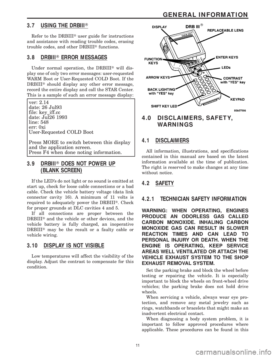
3.7 USING THE DRBIIIT
Refer to the DRBIIItuser guide for instructions
and assistance with reading trouble codes, erasing
trouble codes, and other DRBIIItfunctions.
3.8 DRBIIITERROR MESSAGES
Under normal operation, the DRBIIItwill dis-
play one of only two error messages: user-requested
WARM Boot or User-Requested COLD Boot. If the
DRBIIItshould display any other error message,
record the entire display and call the STAR Center.
This is a sample of such an error message display:
ver: 2.14
date: 26 Jul93
file: key_iff.cc
date: Jul26 1993
line: 548
err: 0xi
User-Requested COLD Boot
Press MORE to switch between this display
and the application screen.
Press F4 when done noting information.
3.9 DRBIIITDOES NOT POWER UP
(BLANK SCREEN)
If the LED's do not light or no sound is emitted at
start up, check for loose cable connections or a bad
cable. Check the vehicle battery voltage (data link
connector cavity 16). A minimum of 11 volts is
required to adequately power the DRBIIIt. Check
for proper grounds at DLC cavities 4 and 5.
If all connections are proper between the
DRBIIItand the vehicle or other devices, and the
vehicle battery is fully charged, an inoperative
DRBIIItmay be the result or a faulty cable or
vehicle wiring.
3.10 DISPLAY IS NOT VISIBLE
Low temperatures will affect the visibility of the
display. Adjust the contrast to compensate for this
condition.
4.0 DISCLAIMERS, SAFETY,
WARNINGS
4.1 DISCLAIMERS
All information, illustrations, and specifications
contained in this manual are based on the latest
information available at the time of publication.
The right is reserved to make changes at any time
without notice.
4.2 SAFETY
4.2.1 TECHNICIAN SAFETY INFORMATION
WARNING: WHEN OPERATING, ENGINES
PRODUCE AN ODORLESS GAS CALLED
CARBON MONOXIDE. INHALING CARBON
MONOXIDE GAS CAN RESULT IN SLOWER
REACTION TIMES AND CAN LEAD TO
PERSONAL INJURY OR DEATH. WHEN THE
ENGINE IS OPERATING, KEEP SERVICE
AREAS WELL VENTILATED OR ATTACH THE
VEHICLE EXHAUST SYSTEM TO THE SHOP
EXHAUST REMOVAL SYSTEM.
Set the parking brake and block the wheel before
testing or repairing the vehicle. It is especially
important to block the wheels on front-wheel drive
vehicles; the parking brake does not hold drive
wheels.
When servicing a vehicle, always wear eye pro-
tection, and remove any metal jewelry such as
rings, watchbands or bracelets that might make an
inadvertent electrical contact.
When diagnosing a body system problem, it is
important to follow approved procedures where
applicable. These procedures can be found in this
11
GENERAL INFORMATION