wheel torque MERCEDES-BENZ SPRINTER 2006 Service Manual
[x] Cancel search | Manufacturer: MERCEDES-BENZ, Model Year: 2006, Model line: SPRINTER, Model: MERCEDES-BENZ SPRINTER 2006Pages: 2305, PDF Size: 48.12 MB
Page 323 of 2305
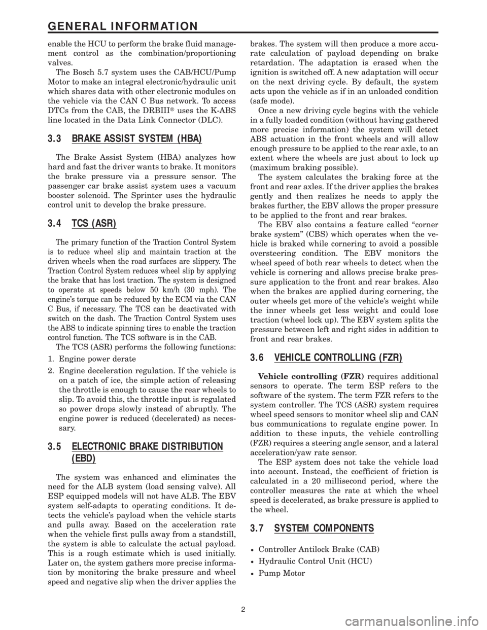
enable the HCU to perform the brake fluid manage-
ment control as the combination/proportioning
valves.
The Bosch 5.7 system uses the CAB/HCU/Pump
Motor to make an integral electronic/hydraulic unit
which shares data with other electronic modules on
the vehicle via the CAN C Bus network. To access
DTCs from the CAB, the DRBIIItuses the K-ABS
line located in the Data Link Connector (DLC).
3.3 BRAKE ASSIST SYSTEM (HBA)
The Brake Assist System (HBA) analyzes how
hard and fast the driver wants to brake. It monitors
the brake pressure via a pressure sensor. The
passenger car brake assist system uses a vacuum
booster solenoid. The Sprinter uses the hydraulic
control unit to develop the brake pressure.
3.4 TCS (ASR)
The primary function of the Traction Control System
is to reduce wheel slip and maintain traction at the
driven wheels when the road surfaces are slippery. The
Traction Control System reduces wheel slip by applying
the brake that has lost traction. The system is designed
to operate at speeds below 50 km/h (30 mph). The
engine's torque can be reduced by the ECM via the CAN
C Bus, if necessary. The TCS can be deactivated with
switch on the dash. The Traction Control System uses
the ABS to indicate spinning tires to enable the traction
control function. The TCS software is in the CAB.
The TCS (ASR) performs the following functions:
1. Engine power derate
2. Engine deceleration regulation. If the vehicle is
on a patch of ice, the simple action of releasing
the throttle is enough to cause the rear wheels to
slip. To avoid this, the throttle input is regulated
so power drops slowly instead of abruptly. The
engine power is reduced (decelerated) as neces-
sary.
3.5 ELECTRONIC BRAKE DISTRIBUTION
(EBD)
The system was enhanced and eliminates the
need for the ALB system (load sensing valve). All
ESP equipped models will not have ALB. The EBV
system self-adapts to operating conditions. It de-
tects the vehicle's payload when the vehicle starts
and pulls away. Based on the acceleration rate
when the vehicle first pulls away from a standstill,
the system is able to calculate the actual payload.
This is a rough estimate which is used initially.
Later on, the system gathers more precise informa-
tion by monitoring the brake pressure and wheel
speed and negative slip when the driver applies thebrakes. The system will then produce a more accu-
rate calculation of payload depending on brake
retardation. The adaptation is erased when the
ignition is switched off. A new adaptation will occur
on the next driving cycle. By default, the system
acts upon the vehicle as if in an unloaded condition
(safe mode).
Once a new driving cycle begins with the vehicle
in a fully loaded condition (without having gathered
more precise information) the system will detect
ABS actuation in the front wheels and will allow
enough pressure to be applied to the rear axle, to an
extent where the wheels are just about to lock up
(maximum braking possible).
The system calculates the braking force at the
front and rear axles. If the driver applies the brakes
gently and then realizes he needs to apply the
brakes further, the EBV allows the proper pressure
to be applied to the front and rear brakes.
The EBV also contains a feature called ªcorner
brake systemº (CBS) which operates when the ve-
hicle is braked while cornering to avoid a possible
oversteering condition. The EBV monitors the
wheel speed of both rear wheels to detect when the
vehicle is cornering and allows precise brake pres-
sure application to the front and rear brakes. Also
when the brakes are applied during cornering, the
outer wheels get more of the vehicle's weight while
the inner wheels get less weight and could lose
traction (wheel lock up). The EBV system splits the
pressure between left and right sides in addition to
front and rear brakes.
3.6 VEHICLE CONTROLLING (FZR)
Vehicle controlling (FZR)requires additional
sensors to operate. The term ESP refers to the
software of the system. The term FZR refers to the
system controller. The TCS (ASR) system requires
wheel speed sensors to monitor wheel slip and CAN
bus communications to regulate engine power. In
addition to these inputs, the vehicle controlling
(FZR) requires a steering angle sensor, and a lateral
acceleration/yaw rate sensor.
The ESP system does not take the vehicle load
into account. Instead, the coefficient of friction is
calculated in a 20 millisecond period, where the
controller measures the rate at which the wheel
speed is decelerated, as brake pressure is applied to
the wheel.
3.7 SYSTEM COMPONENTS
²Controller Antilock Brake (CAB)
²Hydraulic Control Unit (HCU)
²Pump Motor
2
GENERAL INFORMATION
Page 419 of 2305
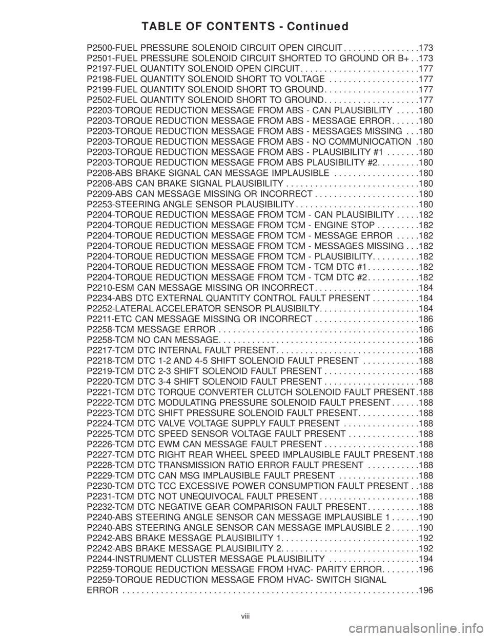
TABLE OF CONTENTS - Continued
P2500-FUEL PRESSURE SOLENOID CIRCUIT OPEN CIRCUIT................173
P2501-FUEL PRESSURE SOLENOID CIRCUIT SHORTED TO GROUND OR B+ . .173
P2197-FUEL QUANTITY SOLENOID OPEN CIRCUIT.........................177
P2198-FUEL QUANTITY SOLENOID SHORT TO VOLTAGE...................177
P2199-FUEL QUANTITY SOLENOID SHORT TO GROUND....................177
P2502-FUEL QUANTITY SOLENOID SHORT TO GROUND....................177
P2203-TORQUE REDUCTION MESSAGE FROM ABS - CAN PLAUSIBILITY.....180
P2203-TORQUE REDUCTION MESSAGE FROM ABS - MESSAGE ERROR......180
P2203-TORQUE REDUCTION MESSAGE FROM ABS - MESSAGES MISSING . . .180
P2203-TORQUE REDUCTION MESSAGE FROM ABS - NO COMMUNIOCATION .180
P2203-TORQUE REDUCTION MESSAGE FROM ABS - PLAUSIBILITY #1.......180
P2203-TORQUE REDUCTION MESSAGE FROM ABS PLAUSIBILITY #2.........180
P2208-ABS BRAKE SIGNAL CAN MESSAGE IMPLAUSIBLE..................180
P2208-ABS CAN BRAKE SIGNAL PLAUSIBILITY............................180
P2209-ABS CAN MESSAGE MISSING OR INCORRECT......................180
P2253-STEERING ANGLE SENSOR PLAUSIBILITY..........................180
P2204-TORQUE REDUCTION MESSAGE FROM TCM - CAN PLAUSIBILITY.....182
P2204-TORQUE REDUCTION MESSAGE FROM TCM - ENGINE STOP.........182
P2204-TORQUE REDUCTION MESSAGE FROM TCM - MESSAGE ERROR.....182
P2204-TORQUE REDUCTION MESSAGE FROM TCM - MESSAGES MISSING . . .182
P2204-TORQUE REDUCTION MESSAGE FROM TCM - PLAUSIBILITY..........182
P2204-TORQUE REDUCTION MESSAGE FROM TCM - TCM DTC #1...........182
P2204-TORQUE REDUCTION MESSAGE FROM TCM - TCM DTC #2...........182
P2210-ESM CAN MESSAGE MISSING OR INCORRECT......................184
P2234-ABS DTC EXTERNAL QUANTITY CONTROL FAULT PRESENT..........184
P2252-LATERAL ACCELERATOR SENSOR PLAUSIBILTY.....................184
P2211-ETC CAN MESSAGE MISSING OR INCORRECT......................186
P2258-TCM MESSAGE ERROR..........................................186
P2258-TCM NO CAN MESSAGE..........................................186
P2217-TCM DTC INTERNAL FAULT PRESENT..............................188
P2218-TCM DTC 1-2 AND 4-5 SHIFT SOLENOID FAULT PRESENT............188
P2219-TCM DTC 2-3 SHIFT SOLENOID FAULT PRESENT....................188
P2220-TCM DTC 3-4 SHIFT SOLENOID FAULT PRESENT....................188
P2221-TCM DTC TORQUE CONVERTER CLUTCH SOLENOID FAULT PRESENT .188
P2222-TCM DTC MODULATING PRESSURE SOLENOID FAULT PRESENT......188
P2223-TCM DTC SHIFT PRESSURE SOLENOID FAULT PRESENT.............188
P2224-TCM DTC VALVE VOLTAGE SUPPLY FAULT PRESENT................188
P2225-TCM DTC SPEED SENSOR VOLTAGE FAULT PRESENT...............188
P2226-TCM DTC EWM CAN MESSAGE FAULT PRESENT....................188
P2227-TCM DTC RIGHT REAR WHEEL SPEED IMPLAUSIBLE FAULT PRESENT .188
P2228-TCM DTC TRANSMISSION RATIO ERROR FAULT PRESENT...........188
P2229-TCM DTC CAN MSG IMPLAUSIBLE FAULT PRESENT.................188
P2230-TCM DTC TCC EXCESSIVE POWER CONSUMPTION FAULT PRESENT . .188
P2231-TCM DTC NOT UNEQUIVOCAL FAULT PRESENT.....................188
P2232-TCM DTC NEGATIVE GEAR COMPARISON FAULT PRESENT...........188
P2240-ABS STEERING ANGLE SENSOR CAN MESSAGE IMPLAUSIBLE 1......190
P2240-ABS STEERING ANGLE SENSOR CAN MESSAGE IMPLAUSIBLE 2......190
P2242-ABS BRAKE MESSAGE PLAUSIBILITY 1.............................192
P2242-ABS BRAKE MESSAGE PLAUSIBILITY 2.............................192
P2244-INSTRUMENT CLUSTER MESSAGE PLAUSIBILITY...................194
P2259-TORQUE REDUCTION MESSAGE FROM HVAC- PARITY ERROR........196
P2259-TORQUE REDUCTION MESSAGE FROM HVAC- SWITCH SIGNAL
ERROR..............................................................196
viii
Page 430 of 2305
small
mass air flow sensor positive deviation
mass air flow sensor signal circuit open or shorted
mass air flow sensor signal voltage too high
mass air flow sensor signal voltage too high
mass air flow sensor signal voltage too low
mass air flow sensor signal voltage too low
mass air flow sensor signal voltage too low
mass air flow sensor signal voltage too low
mass air flow sensor supply voltage too high
mass air flow sensor supply voltage too low
misfire cylinder #1
misfire cylinder #1
misfire cylinder #2
misfire cylinder #2
misfire cylinder #3
misfire cylinder #3
misfire cylinder #4
misfire cylinder #4
misfire cylinder #5
misfire cylinder #5
misfire detected
no message received from skreem
o2 circuit fault
o2 sensor circuit calibration value too high
o2 sensor circuit calibration value too high
o2 sensor circuit calibration value too high
o2 sensor circuit calibration value too low
o2 sensor circuit calibration value too low
o2 sensor circuit calibration value too low
o2 sensor circuit fault
o2 sensor circuit fault
o2 sensor circuit open circuit
o2 sensor circuit open circuit
o2 sensor circuit signal voltage too high
o2 sensor circuit signal voltage too high
o2 sensor circuit signal voltage too low
o2 sensor circuit signal voltage too low
o2 sensor heater circuit fault
o2 sensor low o2 concentration
o2 sensor plausibility
o2 sensor plausibility
o2 sensor plausibility
o2 sensor plausibility
o2 sensor plausibility
o2 sensor signal circuit signal voltage too high
o2 sensor signal circuit signal voltage too high
o2 sensor signal circuit signal voltage too high
o2 sensor signal fault
o2 sensor signal plausibility
s/c excessive acceleration
s/c excessive deceleration
s/c vehicle speed plausibility
sensor supply 1 voltage is too high
sensor supply 1 voltage is too low
sensor supply 2 voltage is too high
sensor supply 2 voltage is too low
sensor supply 3 voltage is too highsensor supply 3 voltage is too low
starter relay circuit ecm thermal overload
starter relay circuit open or shorted to voltage
starter relay circuit short circuit
starter relay circuit short to ground
steering angle sensor plausibility
tcm dtc 1-2 and 4-5 shift solenoid fault present
tcm dtc 2-3 shift solenoid fault present
tcm dtc 3-4 shift solenoid fault present
tcm dtc can msg implausible fault present
tcm dtc ewm can message fault present
tcm dtc internal fault present
tcm dtc modulating pressure solenoid fault present
tcm dtc negative gear comparison fault present
tcm dtc not unequivocal fault present
tcm dtc right rear wheel speed implausible fault
present
tcm dtc shift pressure solenoid fault present
tcm dtc speed sensor voltage fault present
tcm dtc tcc excessive power consumption fault
present
tcm dtc torque converter clutch solenoid fault
present
tcm dtc transmission ratio error fault present
tcm dtc valve voltage supply fault present
tcm message error
tcm no can message
torque reduction message from abs -can plausibility
torque reduction message from abs -message error
torque reduction message from abs -messages miss-
ing
torque reduction message from abs -no communica-
tion
torque reduction message from abs -plausibility #1
torque reduction message from abs plausibility #2
torque reduction message from hvac switch signal
plausibility
torque reduction message from hvac-parity error
torque reduction message from hvac-switch signal
error
torque reduction message from tcm -can plausibil-
ity
torque reduction message from tcm -engine stop
torque reduction message from tcm -message error
torque reduction message from tcm -messages miss-
ing
torque reduction message from tcm -plausibility
torque reduction message from tcm -tcm dtc #1
torque reduction message from tcm -tcm dtc #2
water in fuel sensor signal error
water in fuel sensor -water in fuel
wheel speed sensor plaus -can bus message from
abs
write error to eeprom
7
GENERAL INFORMATION
Page 611 of 2305
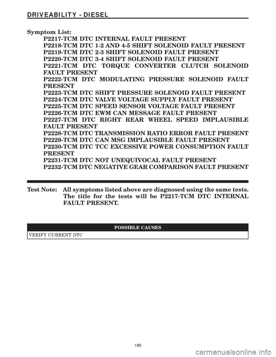
Symptom List:
P2217-TCM DTC INTERNAL FAULT PRESENT
P2218-TCM DTC 1-2 AND 4-5 SHIFT SOLENOID FAULT PRESENT
P2219-TCM DTC 2-3 SHIFT SOLENOID FAULT PRESENT
P2220-TCM DTC 3-4 SHIFT SOLENOID FAULT PRESENT
P2221-TCM DTC TORQUE CONVERTER CLUTCH SOLENOID
FAULT PRESENT
P2222-TCM DTC MODULATING PRESSURE SOLENOID FAULT
PRESENT
P2223-TCM DTC SHIFT PRESSURE SOLENOID FAULT PRESENT
P2224-TCM DTC VALVE VOLTAGE SUPPLY FAULT PRESENT
P2225-TCM DTC SPEED SENSOR VOLTAGE FAULT PRESENT
P2226-TCM DTC EWM CAN MESSAGE FAULT PRESENT
P2227-TCM DTC RIGHT REAR WHEEL SPEED IMPLAUSIBLE
FAULT PRESENT
P2228-TCM DTC TRANSMISSION RATIO ERROR FAULT PRESENT
P2229-TCM DTC CAN MSG IMPLAUSIBLE FAULT PRESENT
P2230-TCM DTC TCC EXCESSIVE POWER CONSUMPTION FAULT
PRESENT
P2231-TCM DTC NOT UNEQUIVOCAL FAULT PRESENT
P2232-TCM DTC NEGATIVE GEAR COMPARISON FAULT PRESENT
Test Note: All symptoms listed above are diagnosed using the same tests.
The title for the tests will be P2217-TCM DTC INTERNAL
FAULT PRESENT.
POSSIBLE CAUSES
VERIFY CURRENT DTC
188
DRIVEABILITY - DIESEL
Page 726 of 2305
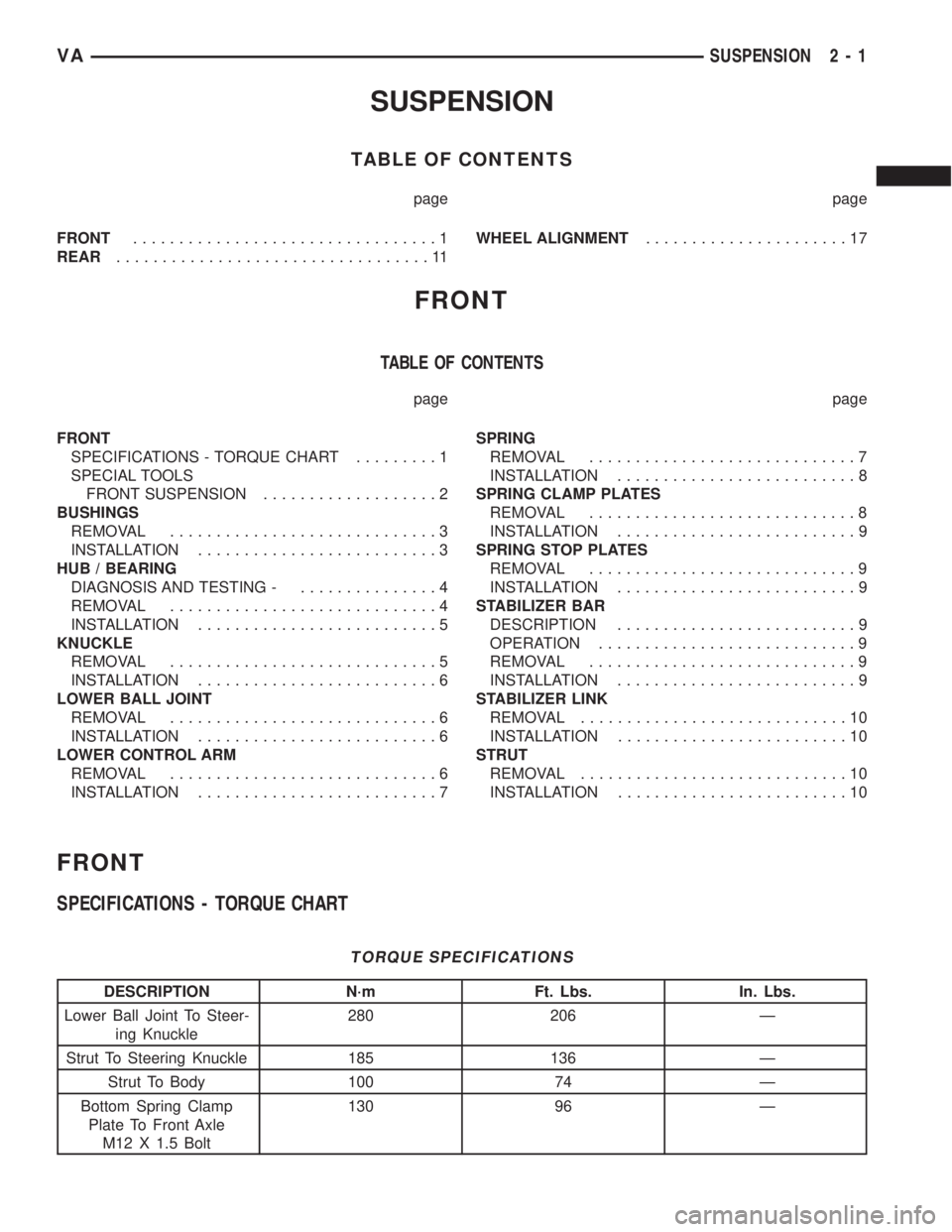
SUSPENSION
TABLE OF CONTENTS
page page
FRONT.................................1
REAR..................................11WHEEL ALIGNMENT......................17
FRONT
TABLE OF CONTENTS
page page
FRONT
SPECIFICATIONS - TORQUE CHART.........1
SPECIAL TOOLS
FRONT SUSPENSION...................2
BUSHINGS
REMOVAL.............................3
INSTALLATION..........................3
HUB / BEARING
DIAGNOSIS AND TESTING -...............4
REMOVAL.............................4
INSTALLATION..........................5
KNUCKLE
REMOVAL.............................5
INSTALLATION..........................6
LOWER BALL JOINT
REMOVAL.............................6
INSTALLATION..........................6
LOWER CONTROL ARM
REMOVAL.............................6
INSTALLATION..........................7SPRING
REMOVAL.............................7
INSTALLATION..........................8
SPRING CLAMP PLATES
REMOVAL.............................8
INSTALLATION..........................9
SPRING STOP PLATES
REMOVAL.............................9
INSTALLATION..........................9
STABILIZER BAR
DESCRIPTION..........................9
OPERATION............................9
REMOVAL.............................9
INSTALLATION..........................9
STABILIZER LINK
REMOVAL.............................10
INSTALLATION.........................10
STRUT
REMOVAL.............................10
INSTALLATION.........................10
FRONT
SPECIFICATIONS - TORQUE CHART
TORQUE SPECIFICATIONS
DESCRIPTION N´m Ft. Lbs. In. Lbs.
Lower Ball Joint To Steer-
ing Knuckle280 206 Ð
Strut To Steering Knuckle 185 136 Ð
Strut To Body 100 74 Ð
Bottom Spring Clamp
Plate To Front Axle
M12 X 1.5 Bolt130 96 Ð
VASUSPENSION 2 - 1
Page 742 of 2305
WHEEL ALIGNMENT
TABLE OF CONTENTS
page page
WHEEL ALIGNMENT
DESCRIPTION........................17
DIAGNOSIS AND TESTING - PRE-ALIGNMENT
INSPECTION.........................17STANDARD PROCEDURE - TOE
ADJUSTMENT........................18
SPECIFICATIONS.....................19
WHEEL ALIGNMENT
DESCRIPTION
NOTE: Camber and Caster are not adjustable on
this vehicle. (TOE ONLY).
NOTE: Suspension components with rubber/ure-
thane bushings should be tightened with the vehi-
cle at normal ride height. It is important to have the
springs supporting the weight of the vehicle when
the fasteners are torqued. If springs are not at their
normal ride position, vehicle ride comfort could be
affected and premature bushing wear may occur.
Wheel alignment involves the correct positioning of
the wheels in relation to the vehicle. The positioning
is accomplished through suspension and steering
linkage adjustments. An alignment is considered
essential for efficient steering, good directional stabil-
ity and to minimize tire wear. The most important
measurements of an alignment are caster, camber
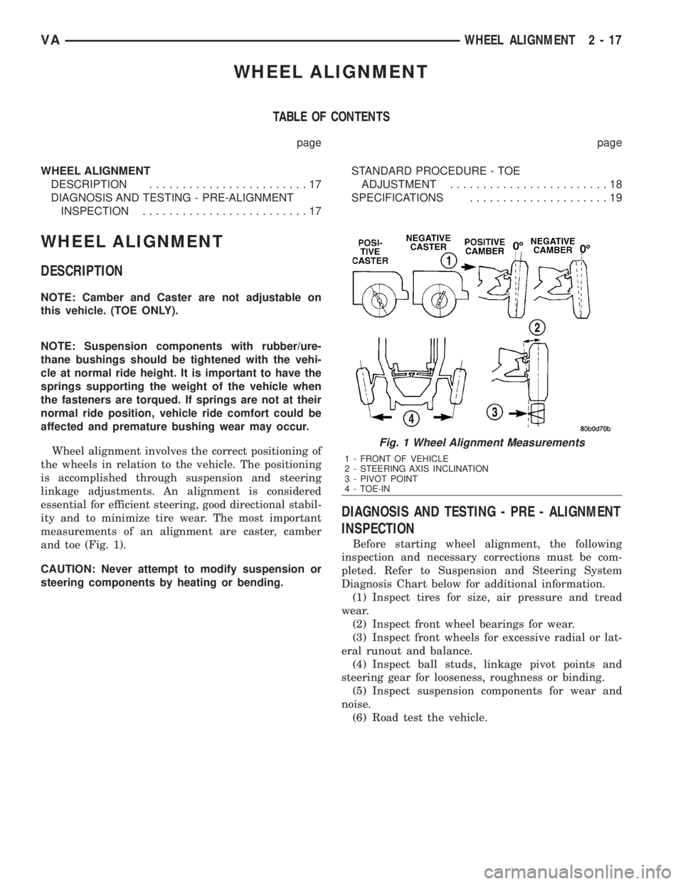
and toe (Fig. 1).
CAUTION: Never attempt to modify suspension or
steering components by heating or bending.
DIAGNOSIS AND TESTING - PRE - ALIGNMENT
INSPECTION
Before starting wheel alignment, the following
inspection and necessary corrections must be com-
pleted. Refer to Suspension and Steering System
Diagnosis Chart below for additional information.
(1) Inspect tires for size, air pressure and tread
wear.
(2) Inspect front wheel bearings for wear.
(3) Inspect front wheels for excessive radial or lat-
eral runout and balance.
(4) Inspect ball studs, linkage pivot points and
steering gear for looseness, roughness or binding.
(5) Inspect suspension components for wear and
noise.
(6) Road test the vehicle.
Fig. 1 Wheel Alignment Measurements
1 - FRONT OF VEHICLE
2 - STEERING AXIS INCLINATION
3 - PIVOT POINT
4 - TOE-IN
VAWHEEL ALIGNMENT 2 - 17
Page 744 of 2305
(4) Tighten the tie rod jam nut to 50 N´m (37 ft.
lbs.).
(5) Verify the specifications
(6) Turn off engine.
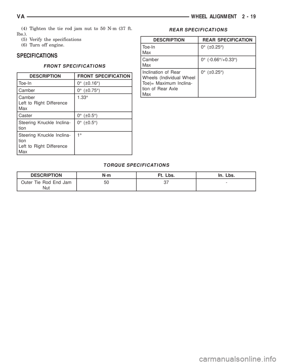
SPECIFICATIONS
FRONT SPECIFICATIONS
DESCRIPTION FRONT SPECIFICATION
Toe-In 0É ( 0.16É)
Camber 0É ( 0.75É)
Camber
Left to Right Difference
Max1.33É
Caster 0É ( 0.5É)
Steering Knuckle Inclina-
tion0É ( 0.5É)
Steering Knuckle Inclina-
tion
Left to Right Difference
Max1É
REAR SPECIFICATIONS
DESCRIPTION REAR SPECIFICATION
Toe-In
Max0É ( 0.25É)
Camber
Max0É (-0.66É/+0.33É)
Inclination of Rear
Wheels (Individual Wheel
Toe)= Maximum Inclina-
tion of Rear Axle
Max0É ( 0.25É)
TORQUE SPECIFICATIONS
DESCRIPTION N´m Ft. Lbs. In. Lbs.
Outer Tie Rod End Jam
Nut50 37 -
VAWHEEL ALIGNMENT 2 - 19
Page 747 of 2305
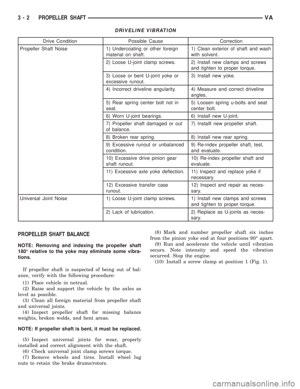
DRIVELINE VIBRATION
Drive Condition Possible Cause Correction
Propeller Shaft Noise 1) Undercoating or other foreign
material on shaft.1) Clean exterior of shaft and wash
with solvent.
2) Loose U-joint clamp screws. 2) Install new clamps and screws
and tighten to proper torque.
3) Loose or bent U-joint yoke or
excessive runout.3) Install new yoke.
4) Incorrect driveline angularity. 4) Measure and correct driveline
angles.
5) Rear spring center bolt not in
seat.5) Loosen spring u-bolts and seat
center bolt.
6) Worn U-joint bearings. 6) Install new U-joint.
7) Propeller shaft damaged or out
of balance.7) Installl new propeller shaft.
8) Broken rear spring. 8) Install new rear spring.
9) Excessive runout or unbalanced
condition.9) Re-index propeller shaft, test,
and evaluate.
10) Excessive drive pinion gear
shaft runout.10) Re-index propeller shaft and
evaluate.
11) Excessive axle yoke deflection. 11) Inspect and replace yoke if
necessary.
12) Excessive transfer case
runout.12) Inspect and repair as neces-
sary.
Universal Joint Noise 1) Loose U-joint clamp screws. 1) Install new clamps and screws
and tighten to proper torque.
2) Lack of lubrication. 2) Replace as U-joints as neces-
sary.
PROPELLER SHAFT BALANCE
NOTE: Removing and indexing the propeller shaft
180É relative to the yoke may eliminate some vibra-
tions.
If propeller shaft is suspected of being out of bal-
ance, verify with the following procedure:
(1) Place vehicle in netrual.
(2) Raise and support the vehicle by the axles as
level as possible.
(3) Clean all foreign material from propeller shaft
and universal joints.
(4) Inspect propeller shaft for missing balance
weights, broken welds, and bent areas.
NOTE: If propeller shaft is bent, it must be replaced.
(5) Inspect universal joints for wear, properly
installed and correct alignment with the shaft.
(6) Check universal joint clamp screws torque.
(7) Remove wheels and tires. Install wheel lug
nuts to retain the brake drums/rotors.(8) Mark and number propeller shaft six inches
from the pinion yoke end at four positions 90É apart.
(9) Run and accelerate the vehicle until vibration
occurs. Note intensity and speed the vibration
occurred. Stop the engine.
(10) Install a screw clamp at position 1 (Fig. 1).
3 - 2 PROPELLER SHAFTVA
Page 784 of 2305
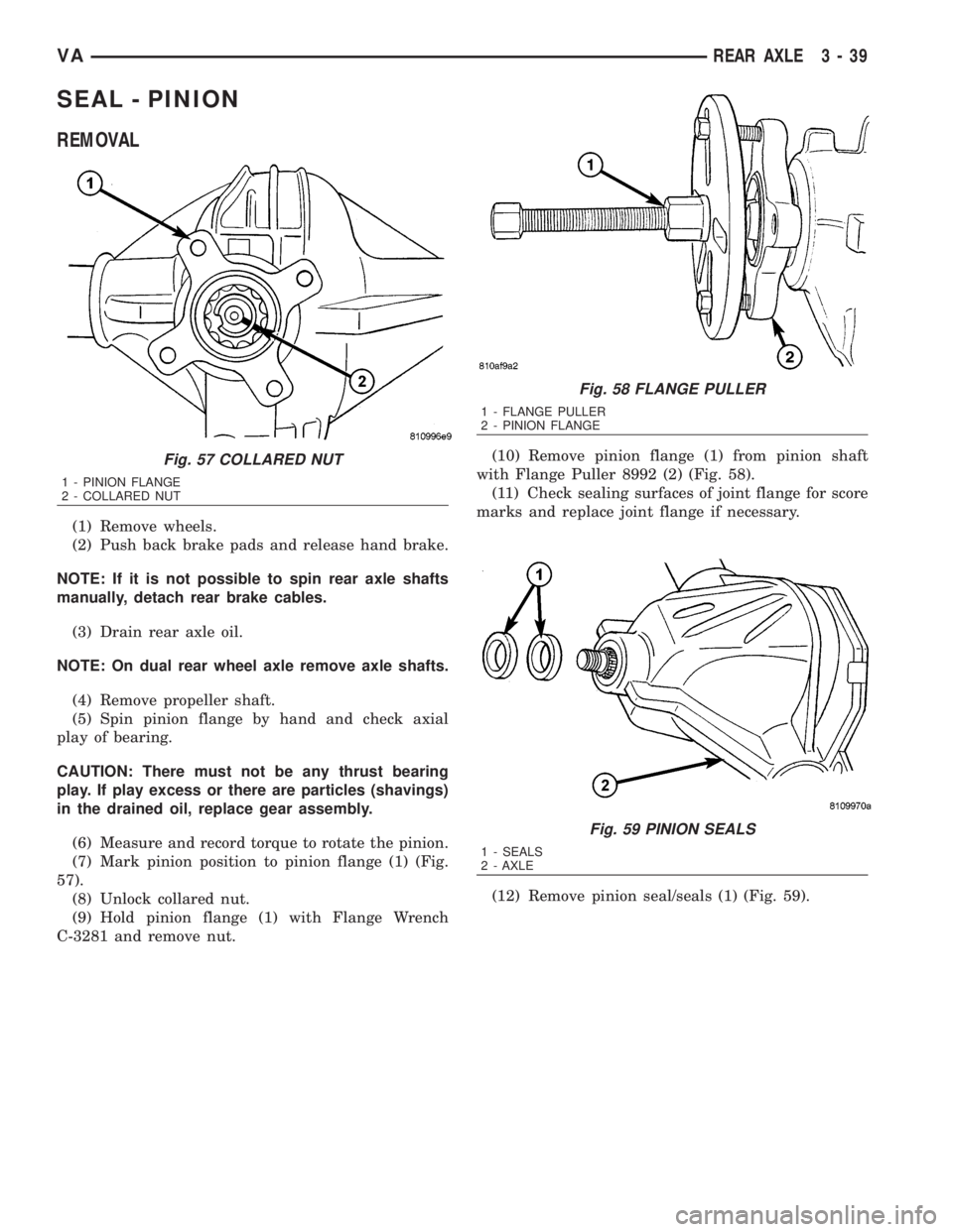
SEAL - PINION
REMOVAL
(1) Remove wheels.
(2) Push back brake pads and release hand brake.
NOTE: If it is not possible to spin rear axle shafts
manually, detach rear brake cables.
(3) Drain rear axle oil.
NOTE: On dual rear wheel axle remove axle shafts.
(4) Remove propeller shaft.
(5) Spin pinion flange by hand and check axial
play of bearing.
CAUTION: There must not be any thrust bearing
play. If play excess or there are particles (shavings)
in the drained oil, replace gear assembly.
(6) Measure and record torque to rotate the pinion.
(7) Mark pinion position to pinion flange (1) (Fig.
57).
(8) Unlock collared nut.
(9) Hold pinion flange (1) with Flange Wrench
C-3281 and remove nut.(10) Remove pinion flange (1) from pinion shaft
with Flange Puller 8992 (2) (Fig. 58).
(11) Check sealing surfaces of joint flange for score
marks and replace joint flange if necessary.
(12) Remove pinion seal/seals (1) (Fig. 59).
Fig. 57 COLLARED NUT
1 - PINION FLANGE
2 - COLLARED NUT
Fig. 58 FLANGE PULLER
1 - FLANGE PULLER
2 - PINION FLANGE
Fig. 59 PINION SEALS
1 - SEALS
2 - AXLE
VAREAR AXLE 3 - 39
Page 790 of 2305
BRAKES
TABLE OF CONTENTS
page page
BRAKES - BASE........................... 1BRAKES - ABS........................... 30
BRAKES - BASE
TABLE OF CONTENTS
page page
BRAKES - BASE
DIAGNOSIS AND TESTING - BASE BRAKE
SYSTEM.............................2
STANDARD PROCEDURE
STANDARD PROCEDURE - MANUAL
BLEEDING............................4
STANDARD PROCEDURE - PRESSURE
BLEEDING............................5
HYDRAULIC/MECHANICAL
SPECIFICATIONS
SPECIFICATIONS - TORQUE CHART.......5
BASE BRAKE.........................6
SPECIAL TOOLS
BRAKES.............................7
BRAKE LINES
STANDARD PROCEDURE
STANDARD PROCEDURE - ISO FLARING . . . 8
STANDARD PROCEDURE - DOUBLE
INVERTED FLARING....................8
BRAKE PADS/SHOES
REMOVAL
REMOVAL - FRONT (SRW)...............8
REMOVAL - FRONT (DRW)...............9
REMOVAL - REAR (16º WHEELS) (SRW)....9
REMOVAL - REAR (15º WHEELS) (SRW) . . . 10
REMOVAL - REAR (DRW)...............10
INSTALLATION
INSTALLATION - FRONT (SRW)...........11
INSTALLATION - FRONT (DRW)..........11
INSTALLATION - REAR (16º WHEELS)
(SRW) ..............................11
INSTALLATION - REAR (16º WHEELS)
(SRW) ..............................11
INSTALLATION - REAR (DRW)...........11
DISC BRAKE CALIPERS
REMOVAL
REMOVAL - FRONT (SRW)..............11
REMOVAL - FRONT (DRW)..............12
REMOVAL - REAR (SRW)...............12
REMOVAL - REAR (DRW)...............13INSTALLATION
INSTALLATION - FRONT (SRW)..........13
INSTALLATION - FRONT (DRW)..........13
INSTALLATION - REAR (SRW)...........14
INSTALLATION - REAR (DRW)...........14
DISC BRAKE CALIPER ADAPTER
REMOVAL
REMOVAL - FRONT....................14
REMOVAL - REAR.....................14
INSTALLATION
INSTALLATION - FRONT................14
INSTALLATION - REAR.................14
FLUID
DIAGNOSIS AND TESTING - BRAKE FLUID
CONTAMINATION.....................15
STANDARD PROCEDURE - BRAKE FLUID
LEVEL..............................15
SPECIFICATIONS
BRAKE FLUID........................15
FLUID RESERVOIR
REMOVAL.............................15
INSTALLATION.........................15
ALB LEVER
REMOVAL.............................16
INSTALLATION.........................16
ALB CONTROLLER
REMOVAL.............................16
INSTALLATION.........................16
ADJUSTMENTS
ADJUSTMENT........................16
MASTER CYLINDER
DIAGNOSIS AND TESTING - MASTER
CYLINDER/POWER BOOSTER...........17
STANDARD PROCEDURE - MASTER
CYLINDER BLEEDING..................18
REMOVAL.............................18
INSTALLATION.........................19
PEDAL
REMOVAL.............................19
INSTALLATION.........................19
VABRAKES 5 - 1